Advertisement
Quick Links
CC2541 Evaluation Module Kit Quick Start Guide
Opening the Box and Running the Bluetooth® Low Energy SimpleBLE Demo Application
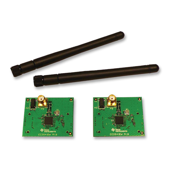
1. Kit Contents
2 x CC2541 Evaluation Modules
2 x Pulse W1010 Antennas
Documentation
The
kit
is
FCC
and
IC
certified
tested/complies
with
ETSI/R&TTE
temperature from 0 to +35°C. The antenna,
W1010 from Pulse, is a ¼ wave dipole antenna
with 2 dBi gain.
Caution!
The kit
contains ESD
sensitive components. Handle with
care to prevent permanent damage.
4. Power Options
There are several ways of applying power to the
SmartRF05EB.
2 x 1.5 V AA Alkaline Batteries
USB
External Power Supply
For the batteries and USB, there are voltage
regulators on the SmartRF05EB that will set the
on-board voltage to 3.3 V. The external power
supply should set a voltage that does not exceed
3.3 V. Note that there should only be one
active power source at any one time.
Warning! To minimize risk of personal injury or
property
damage,
never
use
batteries to power the board.
7. Using the Joystick
The
SimpleBLEPeripheral
application
autonomously and does not require any user
interaction. The SimpleBLECentral application,
however, requires user interaction by means of
joystick U1. Find joystick U1 on the top side of
the SmartRF05EB, immediately below the LCD.
The joystick has five different movements: it can
be moved up, down, left, right, and it can be
pressed in, just like a button. Each movement
performs different actions depending on the state
of the device.
2. Hardware Requirements
The CC2541EMK is an add-on kit to the
CC2540DK. To run the example described in
this Quick Start Guide, you would need two
SmartRF05 Boards (Rev 1.8.1 or later). These
boards are included in the CC2540DK (and
not in the CC2541EMK).
and
over
More information about the SmartRF05EB can
be found in www.ti.com/lit/swru210.
The CC2541EM boards can also be plugged
into a battery board (see
bb) for standalone operation.
5. Power the
Boards
Find jumper P11 on
the top side of each
SmartRF05EB. This jumper is used to set the
power source for the board. Set P11 to "1-2" if
you are using battery power. Set P11 to "2-3" if
SmartRF05EB. To power up the boards, flip the
switch from the "OFF" position to "ON".
rechargeable
Do
not
leave
unattended.
8. Device Discovery
runs
Before the two devices
can connect, the central
device
must
discover the peripheral
device.
To
perform
device discovery, press
up on joystick U1 once.
The LCD on the central
device should display
"Discovering...".
After a few seconds, it should display "Devices
Found 1 / <- To Select". This means that the
central
device
successfully
peripheral. Press left on joystick U1 to view the
address of the peripheral device. This address
should
match
the
peripheral's LCD.
www.ti.com/lprf
Web sites:
E2E Forum:
www.ti.com/lprf-forum
3. Hardware Setup
Connect the antenna to the SMA connector on
the CC2541 evaluation module (CC2541EM).
Tighten the antenna's screw firmly on to the SMA
connector. If not properly connected, you might
see reduced RF performance.
Next, mount the CC2541EMs
firmly on to connectors P5
and
SmartRF05EB.
Caution! To minimize risk of injury, avoid
touching
www.ti.com/tool/soc-
symbolized as hot.
6. Start-up Screen
One of the CC2541EMs will be pre-loaded
with the SimpleBLECentral application, while
the other will be pre-loaded with the
SimpleBLEPeripheral application. The LCD
screens on the two SmartRF05EBs should
display messages similar to those below:
you are using USB or an
external power supply.
Once you have set P11,
find switch P8 on the top
side
of
each
The "0x..." value displayed on each board is
the device address. Every CC2541 device
has a unique address.
EVM
powered
when
9. Establish Connection
To
connection
first
the
press joystick U1
in
board (push it in
like it is a button).
Once
connection
established,
automatically perform service discovery on the
peripheral using the BLE GATT protocol. This
should complete within a few seconds.
discovered
the
The two LCD screens should appear as in the
images below, with the central still displaying
address
seen
on
the
the peripheral's address and the peripheral
having
"Connected":
Be careful that you don't double tap U1 which
would terminate the connection immediately,
giving Disconnected Reason: 22.
Make sure to subscribe to the Low-Power RF
Newsletter to receive information about updates to
documentation, new product releases, and more.
Sign up on the TI web pages.
December 2011
P6
on
the
components
during
operation
establish
a
with
peripheral,
towards
the
the
is
the
central
device
changed
from
"Advertising"
SWRU311
if
will
to
Advertisement

Related Manuals for Texas Instruments CC2541EMK


Summary of Contents for Texas Instruments CC2541EMK
- Page 1 Opening the Box and Running the Bluetooth® Low Energy SimpleBLE Demo Application 1. Kit Contents 2. Hardware Requirements 3. Hardware Setup The CC2541EMK is an add-on kit to the Connect the antenna to the SMA connector on CC2540DK. To run the example described in the CC2541 evaluation module (CC2541EM).
- Page 2 A CC2540 USB Dongle (not included) can be SmartRF Studio allows you to configure the radio, Texas Instruments has a simple tool which can used as a BLE sniffer and monitor packets while run RF performance tests, and run link tests be used to program and flash the CC2541 the SimpleBLE Demo is running.
-
Page 3: Regulatory Compliance Information
EVALUATION BOARD/KIT/MODULE (EVM) ADDITIONAL TERMS Texas Instruments (TI) provides the enclosed Evaluation Board/Kit/Module (EVM) under the following conditions: The user assumes all responsibility and liability for proper and safe handling of the goods. Further, the user indemnifies TI from all claims arising from the handling or use of the goods. - Page 4 For EVMs annotated as FCC – FEDERAL COMMUNICATIONS COMMISSION Part 15 Compliant Caution This device complies with part 15 of the FCC Rules. Operation is subject to the following two conditions: (1) This device may not cause harmful interference, and (2) this device must accept any interference received, including interference that may cause undesired operation.
- Page 5 For EVMs annotated as IC – INDUSTRY CANADA Compliant This Class A or B digital apparatus complies with Canadian ICES-003. Changes or modifications not expressly approved by the party responsible for compliance could void the user’s authority to operate the equipment. Concerning EVMs including radio transmitters This device complies with Industry Canada licence-exempt RSS standard(s).
- Page 6 Also, please do not transfer this product, unless you give the same notice above to the transferee. Please note that if you could not follow the instructions above, you will be subject to penalties of Radio Law of Japan. Texas Instruments Japan Limited (address) 24-1, Nishi-Shinjuku 6 chome, Shinjukku-ku, Tokyo, Japan http://www.tij.co.jp 【ご使用にあたっての注意】...
- Page 7 EVALUATION BOARD/KIT/MODULE (EVM) WARNINGS, RESTRICTIONS AND DISCLAIMERS For Feasibility Evaluation Only, in Laboratory/Development Environments. Unless otherwise indicated, this EVM is not a finished electrical equipment and not intended for consumer use. It is intended solely for use for preliminary feasibility evaluation in laboratory/development environments by technically qualified electronics experts who are familiar with the dangers and application risks associated with handling electrical mechanical components, systems and subsystems.
Need help?
Do you have a question about the CC2541EMK and is the answer not in the manual?
Questions and answers