Table of Contents
Advertisement
Quick Links
CC2510EMK Quick Start Guide
Opening the box an running the Packet Error Rate Test on SmartRF04EB
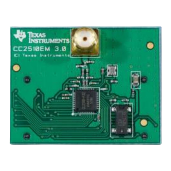
1. Kit Contents
2 x CC2510EM
2 x Pulse W1010 2.4GHz antennas
The boards in this kit are FCC and IC
certified and are tested to comply with
ETSI/R&TTE over temperatures from 0 to
+35°C.
FCC/IC Regulatory Compliance
FCC Part 15 Class A Compliant
IC ICES-003 Class A Compliant
4a. Battery power
There are three different ways of applying
power to the EB:
The first method involves using a battery,
either a 9V or a 4xAA battery pack
connected to the battery connector on the
bottom side of the board
Warning! To minimize risk of personal injury
or property damage, never use rechargeable
batteries to power the board.
5. Set power switch
If a 3.3V source is used as described in 4b
above, the switch should be set to the
leftmost position. For all other cases, the
switch should be set to the rightmost
position. This switch can be used to turn off
the EB by switching it to the opposite
position of that used to turn it on
Do not leave the board powered when
unattended.
1
When using an external power supply, make sure it meets the listed requirements in addition to complying with applicable regional product regulatory and
safety certification requirements such as UL, CSA, VDE, CCC, and PSE
2. How to use the modules
The EMK is an add-on kit to supplement the
CC2510DK with evaluation boards supporting
additional frequency bands.
The CC2510EM boards can be plugged into several
development boards from Texas Instruments. Most
notably, you can use the SmartRF04EB, which is
included in the CC2510-CC2511DK. This board lets
you run a packet error rate (PER) test, control the
device from SmartRF™ Studio and it can be used as
a development platform.
It is also possible to plug the EM into the
SmartRF05EB or the "SoC Battery Board". The
SmartRF05EB, or the SoC BB together with the CC
Debugger, will provide a complete development
environment for the CC2510. See:
http://www.ti.com/tool/soc-bb
This guide will show how to use the modules
together with SmartRF04EB.
4b. DC power
The second method applies DC power using the DC
input jack (right in picture, centre is +, sleeve is
ground), or by connecting a 4-10V voltage source
between the 4-10V and 0V terminals of the power
connector (left in picture). It is also possible to
connect a 3.3V voltage source between the 3.3V and
0V terminals. The on-board voltage regulators will be
bypassed in this case.
1
External Power Supply
Requirements:
Nom Voltage: 6 VDC
Max Current: 800 mA
Efficiency Level V
6. Packet error rate test
When power is applied to the board, the test
program will start. You should see the Chipcon logo
with chip name and revision number as shown
above on the LCD display on both EBs. Pushing
button S1 in the lower right corner of the board will
show the first menu item.
Web sites:
www.ti.com/lprf
www.ti.com/lprf-forum
E2E Forum:
3. Plug EM into EB
Insert a CC2510EM into both SmartRF04EBs. Make
sure the antenna is firmly connected to the SMA
connector.
Caution! The kit contains ESD sensitive
components. Handle with care to prevent
permanent damage. To minimize risk of
injury, avoid touching components during
operation if symbolized as hot.
4c. USB power
The EB can also be powered from the USB bus.
Make sure that the SmartRF™ Studio software is
installed before connecting the EB to the PC;
otherwise you may experience problems in installing
it later due to driver issues.
Note that if multiple power sources are connected,
the source with the highest voltage will power the
EB. This means that you should disconnect any
attached battery when using a lab supply or USB
power; otherwise the battery will be drained.
7. Select Frequency
Select the frequency that you want to use (2420
MHz, 2440 MHz, 2460 MHz or 2480 MHz). Move the
joystick up or down to display the choices and push
button S1 in the lower right corner of the board to
select the displayed frequency.
Make sure to subscribe to the Low-Power RF
Newsletter to receive information about updates to
documentation, new product releases and more. Sign
up on the TI web pages.
September 2013
Advertisement
Table of Contents

Related Manuals for Texas Instruments CC2510EMK


Summary of Contents for Texas Instruments CC2510EMK
- Page 1 CC2510DK with evaluation boards supporting additional frequency bands. The CC2510EM boards can be plugged into several development boards from Texas Instruments. Most notably, you can use the SmartRF04EB, which is included in the CC2510-CC2511DK. This board lets you run a packet error rate (PER) test, control the 2 x CC2510EM device from SmartRF™...
- Page 2 Please visit www.ti.com It you are experiencing problems with this test, please check the following: http://www.ti.com/tool/cc2510emk The data rate affects the obtainable link range. The source code for the packet error rate test For more information about how to use the application is available on the web.
- Page 3 Any exceptions to this are strictly prohibited and unauthorized by Texas Instruments unless user has obtained appropriate experimental/development licenses from local regulatory authorities, which is responsibility of user including its acceptable authorization.
- Page 4 FCC Interference Statement for Class B EVM devices This equipment has been tested and found to comply with the limits for a Class B digital device, pursuant to part 15 of the FCC Rules. These limits are designed to provide reasonable protection against harmful interference in a residential installation. This equipment generates, uses and can radiate radio frequency energy and, if not installed and used in accordance with the instructions, may cause harmful interference to radio communications.
- Page 5 Also, please do not transfer this product, unless you give the same notice above to the transferee. Please note that if you could not follow the instructions above, you will be subject to penalties of Radio Law of Japan. Texas Instruments Japan Limited (address) 24-1, Nishi-Shinjuku 6 chome, Shinjuku-ku, Tokyo, Japan http://www.tij.co.jp...
- Page 6 FDA Class III or similar classification, then you must specifically notify TI of such intent and enter into a separate Assurance and Indemnity Agreement. Mailing Address: Texas Instruments, Post Office Box 655303, Dallas, Texas 75265 Copyright © 2013, Texas Instruments Incorporated...
Need help?
Do you have a question about the CC2510EMK and is the answer not in the manual?
Questions and answers