Advertisement
Quick Links
CC2538-CC2592 Evaluation Module Kit Quick Start Guide
Opening the Box and Running the Packet Error Rate Test
1. Kit Contents
2 x CC2538-CC2592 Evaluation Modules
The RF boards in this kit are FCC and IC certified and
tested/comply with ETSI/R&TTE over temperature from 0
to 35°C.
FCC/IC Regulatory Compliance
FCC Part 15 Class A Compliant
IC ICES-003 Class A Compliant
4. Plug the EM into the 06EB
Insert a CC2538-CC2592EM board into the
SmartRF06EB as shown above.
Note! On the CC2538-CC2592EM, make sure
you connect a jumper on the upper row on
the 4-pin header.
Caution! The kit contains ESD
sensitive components. Handle with
care to prevent permanent damage.
7. Welcome Screen
Turn on power with the Main Power switch.
You should now see the Texas Instruments
logo and a short description of the buttons on
the LCD. Pushing any of the five buttons on the
board will take you to the main menu.
NB! If you don't see anything on the screen
make sure the board is correctly powered
(see step 5 and 6 above).
1
When using an external power supply, make sure it meets the listed requirements in addition to complying with applicable regional product regulatory and safety certification requirements such as
UL, CSA, VDE, CCC, and PSE.
2. How to use the Modules
The EMK is an add-on kit to supplement the
CC2538DK with evaluation boards.
The CC2538-CC2592EM boards can be plugged
into the SmartRF06 Evaluation Board from Texas
Instruments. This board is included in the
CC2538DK and in the SmartRF06EBK.
This board lets you run a packet error rate (PER)
test, control the device from SmartRF™ Studio and
it can be used as a development platform.
It is also possible to connect the EM to other TI
development
boards
with
connectors
This guide will show how to use the modules
together with SmartRF06EB.
5. Power Options
The CC2538-CC2592EM should be powered
through the SmartRF06EB, which will supply a
voltage from 2.1V to 3.6V to the daughter card.
The SmartRF06EB can be powered in several
Jumper
different ways:
USB (5V through USB plug)
2 x 1.5V AAA alkaline batteries
External power supply (see below)
Voltage regulators on the SmartRF06EB will set
the on-board voltage to 2.1V or 3.3V.
External Regulated Power Supply
Nom Voltage: 2.1 to 3.3 VDC. MAX 3.6 VDC.
Max Current: 1000 mA
Efficiency Level V
Warning! To minimize risk of injury or property
damage, never use rechargeable batteries to
power the board.
8. Select Board and Channel
Start by selecting the plug-in board you have,
either the CC2538EM or the combo board
CC2538-CC2591EM.
Then select which channel (frequency) to use.
Web sites:
www.ti.com/lprf
E2E Forum:
www.ti.com/lprf-forum
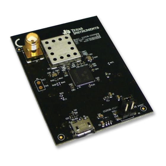
3. CC2538-CC2592EM Overview
SMA connector for
conducted RF testing
(not enabled by default)
CC2592
(under shield)
CC2538
the
appropriate
Micro USB
connector for
testing USB on
CC2538
6. Select Power Source
The power source is selected using the Source
switch on the left hand side of the SmartRF06EB.
In "USB" position, the EM is powered over USB,
running at 3.3V. In "BAT" position, the board is
1
Requirements:
powered from batteries or an external source,
running at 2.1V. The 2.1V regulator can be
bypassed by shorting the pins on the "regulator
bypass" jumper. In this case, the EM is powered
directly from the external source or batteries.
Note that there should only be one active
power source at any one time. Do not leave the
EVM powered when unattended.
9. Select Mode
One of the boards must operate as a transmitter
and the other as a receiver. Select transmitter on
one board ...
... and receiver on the other board.
Make sure to subscribe to the Low-Power RF
Newsletter to receive information about updates to
documentation, new product releases, and more.
Sign up on the TI web pages.
SWRU363
February 2014
PCB Antenna
Caution! Due to
potential high
output power from
the device, please
keep a distance of
at least 20 cm
between the user
and the antenna.
Power Select Jumper
USB 5V to
1-2: Vdd from EB
3.3V LDO
1-3: Vdd from USB
Advertisement

Related Manuals for Texas Instruments CC2538


Summary of Contents for Texas Instruments CC2538
- Page 1 SWRU363 February 2014 CC2538-CC2592 Evaluation Module Kit Quick Start Guide Opening the Box and Running the Packet Error Rate Test 1. Kit Contents 2. How to use the Modules 3. CC2538-CC2592EM Overview The EMK is an add-on kit to supplement the SMA connector for CC2538DK with evaluation boards.
- Page 2 SmartRF Flash Programmer 2. SmartRF™ Studio 1. Download and Install 2. Launch SmartRF Studio 3. Test the Radio In the device control panel for CC2538, select the range extender CC2592. configure radio, After installing the tool, connect the EB to the PC...
- Page 3 IMPORTANT NOTICE Texas Instruments Incorporated and its subsidiaries (TI) reserve the right to make corrections, enhancements, improvements and other changes to its semiconductor products and services per JESD46, latest issue, and to discontinue any product or service per JESD48, latest issue.
Need help?
Do you have a question about the CC2538 and is the answer not in the manual?
Questions and answers