Table of Contents
Advertisement
Quick Links
CC2538 Evaluation Module Kit Quick Start Guide
Opening the Box and Running the Packet Error Rate Test
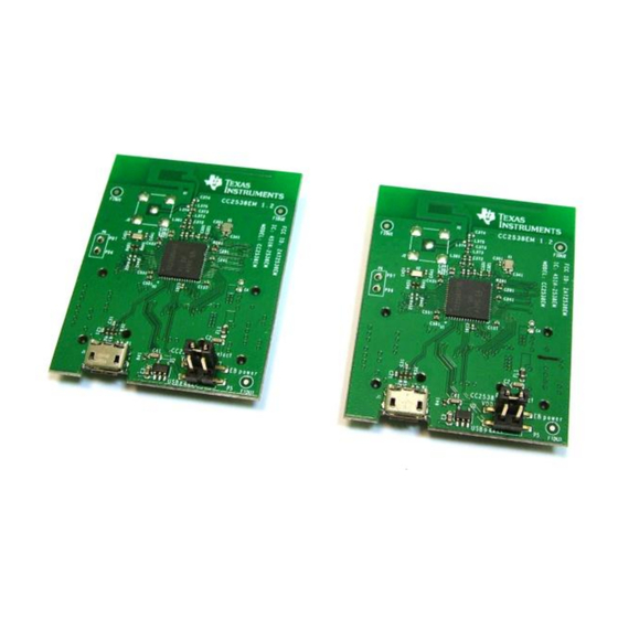
1. Kit Contents
2 x CC2538 Evaluation Modules (CC2538EM)
The EMK is an add-on kit to supplement the
CC2538DK with evaluation boards.
The RF boards in this kit are FCC and IC
certified and tested/comply with ETSI/R&TTE
over temperature from 0 to 35°C.
4. Plug the EM into the 06EB
Insert
a
CC2538EM
board
SmartRF06EB as shown above. NB! Note the
jumper on the upper row on the header on
the CC2538EM.
The
kit
contains
Caution!
sensitive components. Handle with
care to prevent permanent damage.
To minimize risk of injury, avoid
touching
components
operation if symbolized as hot.
7. Welcome Screen
Turn on power with the Main Power switch.
You should now see the Texas Instruments
logo and a short description of the buttons on
the LCD. Pushing any of the five buttons on
the board will take you to the main menu.
NB! If you don't see anything on the screen
make sure the board is correctly powered
(see step 5 and 6 above).
2. How to use the Modules
The CC2538EM boards can be plugged into the
SmartRF06
Evaluation
Instruments.
This
board
CC2538DK and in the SmartRF06EBK.
This board lets you run a packet error rate (PER)
test, control the device from SmartRF™ Studio and
it can be used as a development platform.
It is also possible to connect the EM to other TI
development
boards
connectors
This guide will show how to use the modules
together with SmartRF06EB.
5. Power Options
The CC2538EM should be powered through the
SmartRF06EB, which will supply a voltage from
2.1V to 3.6V to the daughter card. The
SmartRF06EB can be powered in several
different ways:
USB (5V)
2 x 1.5V AAA alkaline batteries
1 x 3.0V CR2032 coin cell battery
External regulated power supply
Voltage regulators on the SmartRF06EB will set
the on-board voltage to 2.1V or 3.3V.
into
the
Warning! To minimize risk of injury or property
damage, never use rechargeable batteries to
power the board. Always select a power source
that is suitably rated for use with this EVM, not
ESD
exceeding 3.6 VDC, with a current output
rating between 0 and 500 mA.
during
8. Select Board and Channel
Start by selecting the plug-in board you have,
either the CC2538EM or the combo board
CC2538-CC2591EM.
Then select which channel (frequency) to use.
www.ti.com/lprf
Web sites:
www.ti.com/lprf-forum
E2E Forum:
3. CC2538EM Overview
Footprint for SMA connector
Board
from
Texas
(for conducted RF testing)
is
included
in
the
CC2538
with
the
appropriate
Micro USB
connector for
testing USB on
CC2538
6. Select Power Source
The power source is selected using the Source
switch on the left hand side of the SmartRF06EB.
In "USB" position, the EM is powered over USB,
running at 3.3V. In "BAT" position, the board is
powered from batteries or an external source,
running at 2.1V. The 2.1V regulator can be
bypassed by shorting the pins on the "regulator
bypass" jumper. In this case, the EM is powered
directly from the external source or batteries.
Note that there should only be one active
power source at any one time. Do not leave the
EVM powered when unattended.
9. Select Mode
One of the boards must operate as a transmitter
and the other as a receiver.
Select transmitter on one board ...
... and receiver on the other board.
The receiver does not require any further set-up
and is now ready to receive packets.
Make sure to subscribe to the Low-Power RF
Newsletter to receive information about updates to
documentation, new product releases, and more.
Sign up on the TI web pages.
SWRU348
April 2013
PCB Antenna
Power Select Jumper
USB 5V to
1-2: Vdd from EB
3.3V LDO
1-3: Vdd from USB
Advertisement
Table of Contents

Related Manuals for Texas Instruments CC2538EMK


Summary of Contents for Texas Instruments CC2538EMK
- Page 1 Then select which channel (frequency) to use. Turn on power with the Main Power switch. You should now see the Texas Instruments logo and a short description of the buttons on the LCD. Pushing any of the five buttons on the board will take you to the main menu.
- Page 2 Sending packets is started and stopped by the error rate based on the number of lost or pressing the Select button. erroneous packets divided by the total number of http://www.ti.com/tool/cc2538emk packets that should have been received. http://www.ti.com/tool/cc2538dk The reference design for the evaluation board can be found here: http://www.ti.com/tool/cc2538em-rd...
- Page 3 Any exceptions to this are strictly prohibited and unauthorized by Texas Instruments unless user has obtained appropriate experimental/development licenses from local regulatory authorities, which is responsibility of user including its acceptable authorization.
- Page 4 FCC Interference Statement for Class B EVM devices This equipment has been tested and found to comply with the limits for a Class B digital device, pursuant to part 15 of the FCC Rules. These limits are designed to provide reasonable protection against harmful interference in a residential installation. This equipment generates, uses and can radiate radio frequency energy and, if not installed and used in accordance with the instructions, may cause harmful interference to radio communications.
- Page 5 Also, please do not transfer this product, unless you give the same notice above to the transferee. Please note that if you could not follow the instructions above, you will be subject to penalties of Radio Law of Japan. Texas Instruments Japan Limited (address) 24-1, Nishi-Shinjuku 6 chome, Shinjuku-ku, Tokyo, Japan http://www.tij.co.jp...
- Page 6 FDA Class III or similar classification, then you must specifically notify TI of such intent and enter into a separate Assurance and Indemnity Agreement. Mailing Address: Texas Instruments, Post Office Box 655303, Dallas, Texas 75265 Copyright © 2013, Texas Instruments Incorporated...
- Page 7 IMPORTANT NOTICE Texas Instruments Incorporated and its subsidiaries (TI) reserve the right to make corrections, enhancements, improvements and other changes to its semiconductor products and services per JESD46, latest issue, and to discontinue any product or service per JESD48, latest issue.
Need help?
Do you have a question about the CC2538EMK and is the answer not in the manual?
Questions and answers