Table of Contents
Advertisement
Quick Links
CC2545EMK Quick Start Guide
Opening the Box and Running the Packet Error Rate Test Application
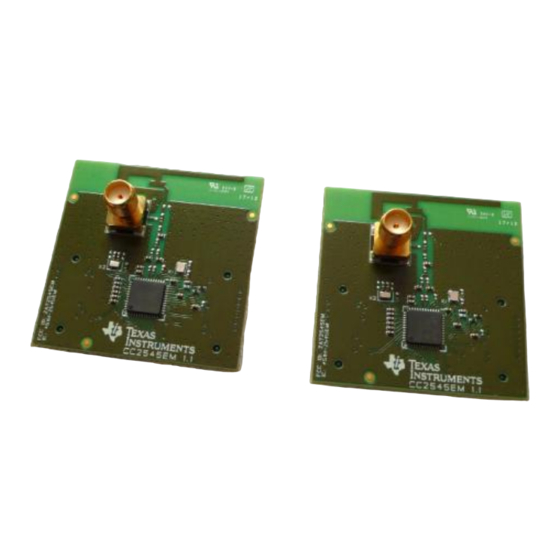
1. Kit Contents
2 x CC2545 Evaluation Modules (EM)
Documentation
The RF boards in this kit are FCC and IC
certified and tested/complies with ETSI/R&TTE
over temperature from 0 to +35°C. There is an
on-board PCB antenna on the evaluation
module.
Caution!
The
kit
contains
sensitive components. Handle with
care to prevent permanent damage.
4. Power Options
There are several ways of applying power to the
SmartRF05EB.
USB (5V)
2 x 1.5 V AA Alkaline Batteries
External Power Supply (4-20V)
For the batteries, USB and external power supply
via the DC jack, there are voltage regulators on
the EB that will set the on-board voltage to 3.3 V.
Warning!
To minimize risk of injury or property
damage, never use rechargeable batteries to power
the board. Always select a power source that is
suitably rated for use with this EVM, not exceeding
20 VDC, with a current output rating between 0 and
1500 mA. Note that there should only be one active
power source at any one time.
7. Choosing Mode
The application can be used between two
CC2545EM's. There are two operating modes:
"Remote" and "Master".
After button S1 is pushed at the start up screen,
the mode selection screen (showed below) will
appear. The Remote mode is shown by default.
Press the joystick up and down to change
between master and remote mode and press
button S1 to confirm.
In the Remote mode all the parameters for the
current PER test must be set up before the test
begins (go to step 10).
2. Hardware Requirements
To run the example described in this Quick Start
Guide, you need two CC2545EMs mounted on
SmartRF05 Evaluation Boards (SmartRF05EB -
Rev 1.8.1 or later). Two SmartRF05EBs are
included in the CC2543-CC2544 Development
Kit.
More information about the SmartRF05EB can
be found in www.ti.com/lit/swru210.
ESD
The CC2545EM boards can also be plugged into
a battery board (see www.ti.com/tool/soc-bb) for
standalone operation.
5. Power the Boards
Locate
the
power
source header P11 just
above the LCD on the
EB. Connect pins 1 and
2
if
you
are
using
battery power. Connect
pins 2 and 3 if you are using USB or an external
power supply.
Once you have set P11,
find switch P8 just next to
the DC jack on the EB. To
power up the boards, flip
the switch from the "OFF"
position to "ON".
Do not leave the EVM powered when
unattended.
8. Master Mode (Beacon)
In "Master" mode, the radio will repeatedly (once
every 10 milliseconds) send out a "beacon"
signal (250 kbps, GFSK modulation, 160 kHz
deviation, 2402 MHz) and listen for a response
from the remote device. The Green LED1 will
blink continuously.
No more actions are needed from the user for
the master device to work.
www.ti.com/lprf
Web sites:
E2E Forum:
www.ti.com/lprf-forum
3. Hardware Setup
Mount the CC2545EMs firmly on to connectors
P5 and P6 on the SmartRF05EB.
Caution! To minimize risk of injury, avoid
touching
components
during
symbolized as hot.
6. Start-up Screen
The CC2545EMs are pre-loaded with a
Packet Error Rate (PER) test application.
The LCD screens on the two SmartRF05EBs
should display the messages below:
9. Master Mode (PER test)
Once the beacon is acknowledged by the
"Remote", the actual PER test begins. The PER
test configuration is included in the payload of
the acknowledge packet. The Master device
extracts this information and configures the radio
parameters accordingly. During the PER test,
packets are sent at a fixed repetition rate of 10
msec.
During the test the number of sent packets will
be updated on the LCD display as well as the link
status between the Master and Remote device.
Make sure to subscribe to the Low-Power RF
Newsletter to receive information about updates to
documentation, new product releases, and more.
Sign up on the TI web pages.
SWRU320
June 2012
operation
if
Advertisement
Table of Contents

Related Manuals for Texas Instruments CC2545EMK


Summary of Contents for Texas Instruments CC2545EMK
- Page 1 SWRU320 June 2012 CC2545EMK Quick Start Guide Opening the Box and Running the Packet Error Rate Test Application 1. Kit Contents 2. Hardware Requirements 3. Hardware Setup To run the example described in this Quick Start Mount the CC2545EMs firmly on to connectors Guide, you need two CC2545EMs mounted on P5 and P6 on the SmartRF05EB.
- Page 2 SmartRF Flash Programmer IAR Embedded Workbench SmartRF Studio allows you to configure the radio, Texas Instruments has a simple tool which can To develop software, program, and debug the run RF performance tests, and run link tests be used to program and flash the CC2545.
- Page 3 IMPORTANT NOTICE Texas Instruments Incorporated and its subsidiaries (TI) reserve the right to make corrections, modifications, enhancements, improvements, and other changes to its products and services at any time and to discontinue any product or service without notice. Customers should obtain the latest relevant information before placing orders and should verify that such information is current and complete.
Need help?
Do you have a question about the CC2545EMK and is the answer not in the manual?
Questions and answers