
Related Manuals for Texas Instruments CC2591


Summary of Contents for Texas Instruments CC2591
- Page 1 CC2591 Evaluation Module Kit Quick Start Guide Downloaded from Elcodis.com electronic components distributor...
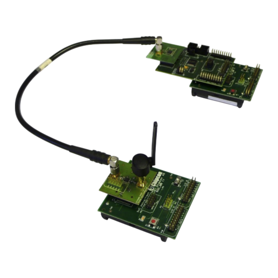
- Page 2 CC2591. Note that since there are no discrete control lines between the radio node and CC2591 in the example below, control of the LNA and PA enable signals has to be done manually by placing jumpers on header P5.
- Page 3 SWRU170 In order to test the performance of the CC2591 PA, connect a signal generator to P4 (radio side) and a spectrum analyzer to P3 (antenna side). To test the LNA, reverse the connections. The CC2591EM contains a 2x5 pin row header (P5). This can be used both to power and control the CC2591.
- Page 4 IMPORTANT NOTICE Texas Instruments Incorporated and its subsidiaries (TI) reserve the right to make corrections, modifications, enhancements, improvements, and other changes to its products and services at any time and to discontinue any product or service without notice. Customers should obtain the latest relevant information before placing orders and should verify that such information is current and complete.
Need help?
Do you have a question about the CC2591 and is the answer not in the manual?
Questions and answers