
Subscribe to Our Youtube Channel
Related Manuals for Kramer PIP-400


Summary of Contents for Kramer PIP-400
- Page 1 Kramer Electronics, Ltd. USER MANUAL Models: PIP-400, Picture in Picture Inserter / Quad Split PIP-500, Picture in Picture Inserter / Quad Split...
-
Page 2: Table Of Contents
Technical Specifications Communication Protocol Figures Figure 1: PIP-400 Picture in Picture Inserter / Quad Split Figure 2: PIP-500 Picture in Picture Inserter / Quad Split Figure 3: Connecting the PIP-500 Picture in Picture Inserter / Quad Split Figure 4: Connecting a PC without using a Null-modem Adapter... - Page 3 Table 7: Video Settings Submenu Features Table 8: Presets Submenu Features Table 9: Technical Specifications of the Picture in Picture Inserter / Quad Split Machines Table 10: Protocol Definitions Table 11: Instruction Codes for the Communication Protocol Contents KRAMER: SIMPLE CREATIVE TECHNOLOGY...
-
Page 4: Introduction
2 Download up-to-date Kramer user manuals from our Web site at http://www.kramerelectronics.com 3 The complete list of Kramer cables is on our Web site at http://www.kramerelectronics.com 4 This quick start also applies to the PIP-400 which has four sets of inputs instead of five Introduction... - Page 5 INPUT 4 INPUT 1 Getting Started INPUT 5 INPUT 2 INPUTS LAYER FREEZE ENTER KRAMER: SIMPLE CREATIVE TECHNOLOGY INPU TS LAYE R FR EEZE ENTER ES C OUTPUT INPUT 3 QUAD OUT MENU Items: MODE: OSD: BORDER: VIDEO SETTINGS: INPUT SELECT:...
-
Page 6: Overview
Overview The high performance PIP-400/PIP-500 is a picture-in-picture inserter for composite video, s-Video (YC) and component video (YUV The PIP-400/PIP-500 features: A multi standard picture-in-picture video inserter designed to accept up to five video sources and display them all on the same screen simultaneously... -
Page 7: Your Picture In Picture Inserter / Quad Split Machines
Your Picture in Picture Inserter / Quad Split Machines This section defines each of the Picture-in-Picture Inserter machines: Figure 1 illustrates the PIP-400 Picture in Picture Inserter / Quad Split Figure 2 illustrates the PIP-500 Picture in Picture Inserter / Quad Split Table 1 and Table 2 define the Picture in Picture Inserter / Quad Split machines. -
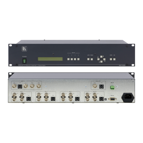
Page 8: Figure 1: Pip-400 Picture In Picture Inserter / Quad Split
Your Picture in Picture Inserter / Quad Split Machines INPUT 4 INPUT 1 INPUT 2 Figure 1: PIP-400 Picture in Picture Inserter / Quad Split INPUTS LAYER FREEZE QUAD OUT INPUT 3 OUTPUT ENTER RELAY RS-232 FUSE... -
Page 9: Figure 2: Pip-500 Picture In Picture Inserter / Quad Split
INPUT 1 Your Picture in Picture Inserter / Quad Split Machines INPUTS INPUT 5 INPUT 2 INPUT 3 Figure 2: PIP-500 Picture in Picture Inserter / Quad Split LAYER FREEZE ENTER QUAD OUT RELAY OUTPUT RS-232 KRAMER: SIMPLE CREATIVE TECHNOLOGY FUSE... -
Page 10: Table 1: Front Panel Picture In Picture Inserter / Quad Split Features
Exits the OSD Menu; moves back to the previous level; stops the execution of a command 1 See Figure 5 2 PIP-400 has four input buttons and PIP-500 has five input buttons 3 Illuminates when the image is frozen 4 See section 7.1.1.1 5 See section 7.1.4... -
Page 11: Table 2: Rear Panel Picture In Picture Inserter / Quad Split Features
CV BNC Connector 1 The PIP-400 has 4 sets of inputs; the PIP-500 has 5 sets. Each set includes CV; Y, B-Y, R-Y; and Y/C 2 For component video, connect all 3 connectors: Y, B-Y, R-Y (also known as Y, Pb/Cb, Pr/Cr; or YUV) -
Page 12: Installing On A Rack
Always mount the machine in the rack before you attach any cables or connect the machine to the power If you are using a Kramer rack adapter kit (for a machine that is not 19"), see the Rack Adapters user manual for... -
Page 13: Connecting The Pip-500 Picture In Picture Inserter / Quad Split
Connect the power cord 1 From this section on, all the information is relevant to the PIP-400 and PIP-500 machines, unless noted otherwise 2 Switch OFF the power on each device before connecting it to your PIP-500. After connecting your PIP-500, switch ON its... -
Page 14: Figure 3: Connecting The Pip-500 Picture In Picture Inserter / Quad Split
Connecting the PIP-500 Picture in Picture Inserter / Quad Split s-Video Player 4 Betacam Video Player 1 s-Video Player 1 Composite Video Player 2 Component Projector Composite Video Player 5 Composite Composite Video Display Video Player 3 Figure 3: Connecting the PIP-500 Picture in Picture Inserter / Quad Split Video Composite s-Video... -
Page 15: Connecting A Pc
If a Shielded cable is used, connect the shield to PIN 5 Figure 4: Connecting a PC without using a Null-modem Adapter PIN 5 Connected to PIN 5 (Ground) PIN 3 Connected to PIN 2 PIN 2 Connected to PIN 3 KRAMER: SIMPLE CREATIVE TECHNOLOGY Male DB9... -
Page 16: Configuring And Operating Your Pip-500
Configuring and Operating Your PIP-500 Configuring and Operating Your PIP-500 You can configure and operate your PIP-500 via: The front panel buttons, and/or RS-232 serial commands transmitted by a touch screen system, PC, or other serial controller 7.1 Using the Menu Use the front panel buttons to activate the menu. -
Page 17: Figure 5: The Pip-500 Menu Guide
Figure 5: The PIP-500 Menu Guide PIP SIZING PIP POSITION ARROWS TO MOVE WHITE BLACK USE UP/DOWN KEYS USE UP/DOWN KEYS USE UP/DOWN KEYS STORE PRESET 1 STORE PRESET 2 RECALL PRESET 1 RECALL PRESET 2 FACTORY DEFAULT KRAMER: SIMPLE CREATIVE TECHNOLOGY 1/16... -
Page 18: The Mode Submenu
Displays 4 quarter-sized input channels Figure 7. The LCD display shows “QUAD Mode” 1 PIP-400 has four input channels 2 When using the QUAD output, the input and output color formats (PAL or NTSC) must be identical 3 All four inputs (1 to 4) must be connected to achieve a good quality quad split output Function on the screen. -
Page 19: The Video Settings Submenu
Use the up/down arrow buttons to set the brightness Video settings apply to all the input channels. 1 PIP-400 has four input channels 2 If OFF is selected, the selected input channel will not be displayed on the screen Function... -
Page 20: The Presets Submenu
3 In some versions, the labeling does not appear on the 1:1 sized image (in the PIP mode) or when the PIPs overlap 4 For PIP-400, Channel 1 to Channel 4 5 Characters cycle between a and z and between 1 and 0 and space... -
Page 21: Displaying The Layers In The Pip Mode
Press an INPUT button to bring forward that input on the screen. 1 Only one channel can be sized to 1:1, the others should be smaller in size or OFF (see Table 6) buttons to change the remaining characters to blank spaces. KRAMER: SIMPLE CREATIVE TECHNOLOGY... -
Page 22: Selecting A Different Channel As The Background
Configuring and Operating Your PIP-500 7.2.1 Selecting a Different Channel as the Background In the following example, Channel 4 replaces channel 5 as the background. The current screen shows: Channel 5 in the background (PIP SIZING: 1:1) Channel 1 in front (PIP SIZING: 1:4) Channel 2 in front (PIP SIZING: 1:16) Channel 3 in front (PIP sizing: 1:9) Channel 4 in front (PIP sizing: 1:16) -
Page 23: Firmware Upgrade
TENDER programmer software, following the on-screen installation instructions. 8.2 Connecting the PC to the RS-232 Port Before installing the latest Kramer firmware version on a PIP-500 unit, do the following: Connect the RS-232 DB9 rear panel port on the PIP-500 unit to the RS-232 DB9 COM port on your PC, via a straight pin-to-pin cable is used in this case!). -
Page 24: Figure 8: Goal Screen
Click the Open… button to select the new firmware hex file Click the Options… button, select the Inverted Polarity area and click OK. In the Action area, select Erase then Program. Click the START button. The software erases and then programs flash memory. Upon completion of the operation, the System Status Window displays: “Erase and program completed successfully”... -
Page 25: Technical Specifications
1 composite video 1Vpp/75 on a BNC connector on a 4p 1 s-Video 1Vpp, 0.3Vpp/75 connector 1 component video 1Vpp, 0.7Vpp, 0.7Vpp/75 on BNC connectors on a BNC connector on a BNC connector KRAMER: SIMPLE CREATIVE TECHNOLOGY PIP-500 on a 4p on BNC connectors... -
Page 26: Communication Protocol
10 Communication Protocol This RS-232/RS-485 communication protocol uses four bytes of information as defined below. A null-modem connection (pin 2 and pin 3 crossed; pins 5 connected together) is used to link the PIP unit to the controller unit (for example, PC). -
Page 27: Table 11: Instruction Codes For The Communication Protocol
Hex value of ASCII character 0 – OSD off 1 – OSD on 0 – Auto-save off 1 – Auto-save on 2 – for PIP-200 (reply) 3 – for PIP-300 (reply) 4 – for PIP-400 (reply) 5 – for PIP-500 (reply) Software version (reply) - Page 28 DETAILS OF INSTRUCTION SET Instruction 0x00: Reset When machine is turned on, it sends a Reset code to the PC (0x40 0x80 0x80 0x88). If this code is sent to the switchers with Byte3 = 0, it will reset according to the present power-down settings. (See instruction #4 for resetting the PIP to its factory default state).
- Page 29 To freeze input 3, send 0x1e 0x83 0x81 0x88. To find out whether input 3 is frozen, send 0x1e 0xc3 0x80 0x88. In this case the unit would respond by sending 0x5e 0xc3 0x81 0x88. Communication Protocol KRAMER: SIMPLE CREATIVE TECHNOLOGY...
- Page 30 If 0x3d 0xc1 0x80 0x88 is sent to a PIP-300, it would reply by sending 0x7d 0xc1 0x83 0x88 If 0x3d 0xc1 0x80 0x88 is sent to a PIP-400, it would reply by sending 0x7d 0xc1 0x84 0x88 If 0x3d 0xc3 0x80 0x88 is sent to a unit with version number 6.3, it would reply by sending 0x7d 0xc6 0x83 0x88...
- Page 31 EXCLUSION OF DAMAGES The liability of Kramer for any effective products is limited to the repair or replacement of the product at our option. Kramer shall not be liable for: Damage to other property caused by defects in this product, damages based upon inconvenience, loss of use of the product, loss of time, commercial loss;...
- Page 32 For the latest information on our products and a list of Kramer distributors, visit our Web site: www.kramerelectronics.com, where updates to this user manual may be found. We welcome your questions, comments and feedback. Safety Warning: Disconnect the unit from the power supply before opening/servicing.
Need help?
Do you have a question about the PIP-400 and is the answer not in the manual?
Questions and answers