
Related Manuals for Kramer FC-400


Summary of Contents for Kramer FC-400
- Page 1 Kramer Electronics, Ltd. USER MANUAL Model: FC-400 Time Base Corrector / Synchronizer...
-
Page 2: Table Of Contents
Table 1: Front Panel FC-400 Time Base Corrector / Synchronizer Table 2: Rear Panel FC-400 Time Base Corrector / Synchronizer Table 3: Dipswitch Settings Table 4: Test Signals Table 5: Technical Specifications of the FC-400 Time Base Corrector / Synchronizer Contents... -
Page 3: Introduction
GROUP 6: Accessories and Rack Adapters; GROUP 7: Scan Converters and Scalers; and GROUP 8: Cables and Connectors 2 Download up-to-date Kramer user manuals from the Internet at this URL: http://www.kramerelectronics.com 3 The complete list of Kramer cables is on our Web site at http://www.kramerelectronics.com Introduction... - Page 4 Getting Started KRAMER: SIMPLE CREATIVE TECHNOLOGY...
-
Page 5: Overview
Overview The Kramer FC-400 is a format converter and TBC. The FC-400 accepts one input: Composite video or composite video and s-Video. The output may be genlocked to an external reference, or synchronized to the high precision reference timing generator of the FC-400. -
Page 6: Your Fc-400 Time Base Corrector / Synchronizer
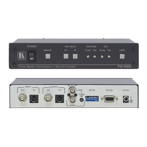
Your FC-400 Time Base Corrector / Synchronizer Your FC-400 Time Base Corrector / Synchronizer Figure 1, Table 1, and Table 2 define the FC-400 Time Base Corrector / Synchronizer. Figure 1: FC-400 Time Base Corrector / Synchronizer Table 1: Front Panel FC-400 Time Base Corrector / Synchronizer... -
Page 7: Connecting Your Fc-400 Time Base Corrector / Synchronizer
3 When only one output is required, connect that output of the FC-400, and leave the other output unconnected 4 Switch OFF the power on each device before connecting it to your FC-400. After connecting your FC-400, switch on its power and then switch on the power on each device 5 Pushed in terminates the input. -
Page 8: Figure 2: Connecting The Fc-400 Time Base Corrector / Synchronizer
Connecting Your FC-400 Time Base Corrector / Synchronizer Connect the 12V DC power adapter (wall transformer) to the 12V DC socket and connect the transformer to the mains electricity. Figure 2: Connecting the FC-400 Time Base Corrector / Synchronizer KRAMER: SIMPLE CREATIVE TECHNOLOGY... -
Page 9: Connecting A Pc
Connecting Your FC-400 Time Base Corrector / Synchronizer 5.1 Connecting a PC To connect a PC to the FC-400 unit, using the Null-modem adapter provided with the machine (recommended): Connect the RS-232 DB9 rear panel port on the FC-400 unit to the... -
Page 10: Dipswitch Settings
Connecting Your FC-400 Time Base Corrector / Synchronizer 5.2 Dipswitch Settings The FC-400 dipswitch settings are defined in Table 3 and Table 4: Dipswitch Set as follows: Reserved for future use Output Standard ON for PAL; OFF for NTSC ON for enabling automatic gain control... -
Page 11: Technical Specifications
WEIGHT: ACCESSORIES: 1 Specifications are subject to change without notice Technical Specifications of the FC-400 Time Base Corrector / Synchronizer 1 composite video - 1 Vpp / 75 on a BNC connector 1 YC - 1 Vpp/75 (Y), 0.3Vpp/75 1 SYNC (Genlock): Looped 75 / Hi-Z on BNC connectors... -
Page 12: Communication Protocol
0 - PAL B 3 - NT 3 0 - OFF 1 - ON 0 - OFF 1 – ON 0 – No genlock 1 – Genlock 0 – Input detected 1 – No input signal KRAMER: SIMPLE CREATIVE TECHNOLOGY... - Page 13 First byte = I; Second byte = D; Third byte = E MACHINE TO PC: --------------------------MACHINE POWER-UP-------- From machine: -------------------------CHANGE MADE VIA FRONT PANEL KEYS-------- From machine: I = 33; D = PARAMETER NUMBER; E = PARAMETER PC TO MACHINE: -------------------------RESET VIDEO (PSEUDO POWER UP) -------- From PC: I = 0;...
- Page 14 EXCLUSION OF DAMAGES The liability of Kramer for any effective products is limited to the repair or replacement of the product at our option. Kramer shall not be liable for: Damage to other property caused by defects in this product, damages based upon inconvenience, loss of use of the product, loss of time, commercial loss;...
- Page 15 For the latest information on our products and a list of Kramer distributors, visit our Web site: www.kramerelectronics.com, where updates to this user manual may be found. We welcome your questions, comments and feedback. Safety Warning: Disconnect the unit from the power supply before opening/servicing.
Need help?
Do you have a question about the FC-400 and is the answer not in the manual?
Questions and answers