
Related Manuals for Kramer PIP-200XL


Summary of Contents for Kramer PIP-200XL
- Page 1 Kramer Electronics, Ltd. USER MANUAL Models: PIP-200xl, Picture in Picture Inserter PIP-300, Picture in Picture Inserter...
-
Page 2: Table Of Contents
Upgrading Firmware Technical Specifications Communication Protocol Figures Figure 1: PIP-200xl Picture in Picture Inserter Figure 2: PIP-300 Picture in Picture Inserter Figure 3: Connecting the PIP-300 Picture in Picture Inserter Figure 4: Connecting a PC without using a Null-modem Adapter... - Page 3 Table 6: Recommended PIP sizes Table 7: Video Settings Submenu Features Table 8: Presets Submenu Features Table 9: Technical Specifications of the PIP-200xl and PIP-300 Picture in Picture Inserter Table 10: Protocol Definitions Table 11: Instruction Codes for the Communication Protocol...
-
Page 4: Introduction
2 Download up-to-date Kramer user manuals from our Web site at http://www.kramerelectronics.com 3 The complete list of Kramer cables is on our Web site at http://www.kramerelectronics.com 4 This quick start also applies for the PIP-200xl which has two sets of inputs instead of three Introduction... - Page 5 Getting Started MENU Items MODE: OSD: BORDER: VIDEO SETTINGS: ENTER INPUT SELECT: OUTPUT STANDARD: PRESETS: LABELING: KRAMER: SIMPLE CREATIVE TECHNOLOGY...
-
Page 6: Overview
Non-volatile memory that retains the last setting, after switching the power off and then on again Using the PIP-200xl or the PIP-300 you can do the following: Position sources on the screen as desired and select their size from a list... -
Page 7: Your Picture In Picture Inserter Machines
Your Picture in Picture Inserter Machines This section defines each of the Picture-in-Picture Inserter machines: Figure 1 illustrates the PIP-200xl Picture in Picture Inserter Figure 2 illustrates the PIP-300 Picture in Picture Inserter Table 1 and Table 2 define the Picture in Picture Inserter machines. -
Page 8: Figure 1: Pip-200Xl Picture In Picture Inserter
Your Picture in Picture Inserter Machines Figure 1: PIP-200xl Picture in Picture Inserter... -
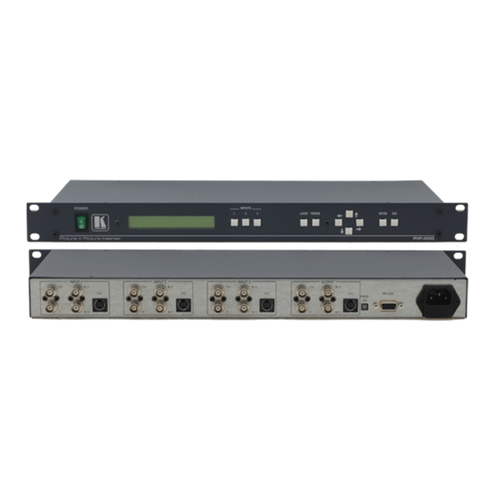
Page 9: Figure 2: Pip-300 Picture In Picture Inserter
Your Picture in Picture Inserter Machines Figure 2: PIP-300 Picture in Picture Inserter KRAMER: SIMPLE CREATIVE TECHNOLOGY... -
Page 10: Table 1: Front Panel Picture In Picture Inserter Features
5 See section 7.1.4 6 The PIP-200xl has 2 sets of inputs; the PIP-300 has 3 sets of inputs. Each set includes CV; Y, B-Y, R-Y; and Y/C 7 For component video, connect all 3 connectors: Y, B-Y, R-Y (also known as Y, Pb/Cb, Pr/Cr or YUV) -
Page 11: Installing On A Rack
Always mount the machine in the rack before you attach any cables or connect the machine to the power If you are using a Kramer rack adapter kit (for a machine that is not 19"), see the Rack Adapters user manual for... -
Page 12: Connecting The Pip-300 Picture In Picture Inserter
Connect the power cord 1 From this section on, all the information is relevant to both the PIP-200xl and the PIP-300 machines, unless noted otherwise 2 Switch OFF the power on each device before connecting it to your PIP-300. After connecting your PIP-300, switch ON its... -
Page 13: Figure 3: Connecting The Pip-300 Picture In Picture Inserter
Connecting the PIP-300 Picture in Picture Inserter Betacam Video Player 1 Component Video Projector s-Video Player 1 RS-232 Composite Video Player 2 Composite Composite s-Video Video Video Display Display Player 3 Figure 3: Connecting the PIP-300 Picture in Picture Inserter KRAMER: SIMPLE CREATIVE TECHNOLOGY... -
Page 14: Connecting A Pc
Connecting the PIP-300 Picture in Picture Inserter 6.1 Connecting a PC To connect a PC to the PIP-300 unit, using the Null-modem adapter provided with the machine (recommended): Connect the RS-232 DB9 rear panel port on the PIP-300 unit to the Null-modem adapter and connect the Null-modem adapter with a 9-wire flat cable to the RS-232 DB9 port on your PC To connect a PC to the PIP-300 unit, without using a Null-modem adapter:... -
Page 15: Configuring And Operating Your Pip-300
3 The menu times out after a minute, both on the LCD display and on the OSD 4 Menu still appears on the LCD display even when deactivated in the OSD 5 The machine is set to Single mode, Channel 1, default video settings and default labeling 2, 3 Function KRAMER: SIMPLE CREATIVE TECHNOLOGY settings,... -
Page 16: Figure 5: The Pip-300 Menu Guide
Configuring and Operating your PIP-300 MODE BORDER VIDEO SETTINGS ENTER INPUT SELECT OUTPUT STANDARD PRESETS LABELING Figure 5: The PIP-300 Menu Guide SINGLE PIP SIZING PIP POSITION WHITE COLOUR BLACK USE UP/DOWN CONTRAST KEYS USE UP/DOWN SATURATION KEYS USE UP/DOWN BRIGHTNESS KEYS COMPOSITE... -
Page 17: The Mode Submenu
Use the PIP POSITION Use the and horizontally 1 PIP-200xl has two input channels 2 If OFF is selected, the selected input channel will not be displayed on the screen Table 4: The MODE Submenu Features Function on the screen. Once the PIP mode is selected, the PIP SIZING... -
Page 18: The Video Settings Submenu
Configuring and Operating your PIP-300 When using one of the inputs as a full-sized background (PIP size 1/1), it is recommended to limit the sizes of the other PIP windows according to Table 6. Combinations having window sizes larger than recommended, may result in intermittent interruptions in the picture. -
Page 19: The Labeling Submenu
1 In some versions, the labeling does not appear on the 1:1 sized image (in the PIP mode) or when the PIPs overlap 2 For PIP-200xl, Channel 1 and Channel 2 3 Characters cycle between a and z, and between 1 and 0 and space... -
Page 20: Displaying The Layers In The Pip Mode
Configuring and Operating your PIP-300 7.2 Displaying the Layers in the PIP Mode To display a picture in picture on the screen, do the following: Select an input. Select the PIP mode. Size and position each layer as desired Press an INPUT button to bring forward that input on the screen. 7.2.1 Selecting a Different Channel as the Background In the following example, Channel 2 replaces Channel 3 as the background. -
Page 21: Firmware Upgrade
TENDER programmer software, following the on-screen installation instructions. 8.2 Connecting the PC to the RS-232 Port Before installing the latest Kramer firmware version on a PIP-300 unit, do the following: Connect the RS-232 DB9 rear panel port on the PIP-300 unit to the RS-232 DB9 COM port on your PC, via a straight pin-to-pin cable null-modem adapter is used in this case!). -
Page 22: Figure 7: Goal Screen
Click the Open… button to select the new firmware hex file Click the Options… button, select the Inverted Polarity area and Click OK. In the Action area, select Erase then Program. Click the START button. The software erases and then programs flash memory. Upon Completion of the operation, the System Status Window displays: “Erase and program completed successfully”... -
Page 23: Technical Specifications
ACCESSORIES: 1 Measurements relate to composite video, unless otherwise stated 2 Specifications are subject to change without notice Technical Specifications of the PIP-200xl and PIP-300 Picture in Picture Inserter PIP-200xl 2 sets, each with: 1 composite video 1Vpp/75 on a BNC connector 1 s-Video 1Vpp, 0.3Vpp/75... -
Page 24: Communication Protocol
10 Communication Protocol This RS-232/RS-485 communication protocol uses four bytes of information as defined below. A null-modem connection (pin 2 and pin 3 crossed; pins 5 connected together) is used to link the PIP unit to the controller unit (for example, PC). -
Page 25: Table 11: Instruction Codes For The Communication Protocol
1 to 5 – input number 1 to 5 – input number 1 to 5 – input number 1 to 5 – input number KRAMER: SIMPLE CREATIVE TECHNOLOGY BYTE3 0 for single mode (non-PIP) 1 for PIP mode 2 for QUAD... - Page 26 DETAILS OF INSTRUCTION SET Instruction 0x00: Reset When machine is turned on, it sends a Reset code to the PC (0x40 0x80 0x80 0x88). If this code is sent to the switchers with Byte3 = 0, it will reset according to the present power-down settings. (See instruction #4 for resetting the PIP to its factory default state).
- Page 27 To freeze input 3, send 0x1e 0x83 0x81 0x88. To find out whether input 3 is frozen, send 0x1e 0xc3 0x80 0x88. In this case the unit would respond by sending 0x5e 0xc3 0x81 0x88. Communication Protocol KRAMER: SIMPLE CREATIVE TECHNOLOGY...
- Page 28 To request the character of a label, define Byte2 as above, and set the RQ bit. The unit responds by setting Byte3 appropriately. For example: To label input 3 as "KRAMER", send the following data: 0x26 0x83 0xcb 0x88 ("K" defined to character 6) 0x25 0x83 0xd2 0x88 ("R" defined to character 5) 0x24 0x83 0xc1 0x88 ("A"...
- Page 29 EXCLUSION OF DAMAGES The liability of Kramer for any effective products is limited to the repair or replacement of the product at our option. Kramer shall not be liable for: Damage to other property caused by defects in this product, damages based upon inconvenience, loss of use of the product, loss of time, commercial loss;...
- Page 30 For the latest information on our products and a list of Kramer distributors, visit our Web site: www.kramerelectronics.com, where updates to this user manual may be found. We welcome your questions, comments and feedback. Safety Warning: Disconnect the unit from the power supply before opening/servicing.
Need help?
Do you have a question about the PIP-200XL and is the answer not in the manual?
Questions and answers