Kramer VM-1610 User Manual
Hide thumbs
Also See for VM-1610:
- User manual (17 pages) ,
- Quick start manual (2 pages) ,
- User manual (14 pages)

Related Manuals for Kramer VM-1610


Summary of Contents for Kramer VM-1610
- Page 1 Kramer Electronics, Ltd. Preliminary USER MANUAL Models: VM-1610, 1:10 Balanced Audio-Stereo Distributor VM-80A, 1:8 Audio Distributor...
-
Page 2: Table Of Contents
Figures Figure 1: VM-1610 1:10 Balanced Audio-Stereo Distributor Figure 2: VM-80A 1:8 Audio Distributor Functions Figure 3: Connecting the VM-1610 in a 1:10 Configuration Figure 4: Connecting the VM-80A in a 1:8 Configuration Tables Table 1: VM-1610 1:10 Balanced Audio-Stereo Distributor Functions... -
Page 3: Introduction
2 We recommend that you use only the power cord supplied with this device 3 Download up-to-date Kramer user manuals from our Web site at http://www.kramerelectronics.com 4 The complete list of Kramer cables is on our Web site at http://www.kramerelectronics.com... -
Page 4: Quick Start
Getting Started Quick Start This quick start chart summarizes the basic setup and operation steps. KRAMER: SIMPLE CREATIVE TECHNOLOGY... -
Page 5: Overview
Your VM-1610 and VM-80A Distribution Amplifiers Section defines the VM-1610 and section defines the VM-80A distribution amplifiers. Your VM-1610 1:10 Balanced Audio-Stereo Distributor Figure 1 Table 1 define the VM-1610. 1 Available from Kramer Electronics on our Web site at http://www.kramerelectronics.com... -
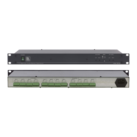
Page 6: Figure 1: Vm-1610 1:10 Balanced Audio-Stereo Distributor
Your VM-1610 and VM-80A Distribution Amplifiers 1:10 Balanced Audio-Stereo Distributor Figure 1: VM-1610 KRAMER: SIMPLE CREATIVE TECHNOLOGY... -
Page 7: Your Vm-80A 1:8 Audio Distributor
Your VM-1610 and VM-80A Distribution Amplifiers Table 1: VM-1610 1:10 Balanced Audio-Stereo Distributor Functions Feature Function POWER Switch Illuminated power switch to turn the unit on and off CH 2 LEVEL (LEFT, RIGHT) Trimmers Controls the left and right audio gains of channel 2... -
Page 8: Installing The Vm-1610 In A Rack
Power Connector with Fuse AC connector enabling power supply to the unit Installing the VM-1610 in a Rack This section describes how to install the VM-1610 in a rack. Before Installing in a rack How to Rack Mount Before installing in a rack, be sure that the environment is... -
Page 9: Connecting The Vm-1610 And Vm-80A
The Channel 2 audio inputs are distributed to the Channel 2 audio outputs. 1 Switch OFF the power on each device before connecting it to your VM-1610. After connecting your VM-1610, switch on its power and then switch on the power on each device... -
Page 10: Connecting The Vm-80A Distribution Amplifier
7. Adjust the right and left audio levels by turning the CH1 and CH2 LEVEL trimmers with a small screwdriver. Figure 3: Connecting the VM-1610 in a 1:10 Configuration Connecting the VM-80A Distribution Amplifier To connect the VM-80A in a 1:8 configuration, as shown in... -
Page 11: Figure 4: Connecting The Vm-80A In A 1:8 Configuration
Connecting the VM-1610 and VM-80A 5. Adjust the right and left audio levels by turning the CH1 and CH2 LEVEL trimmers with a small screwdriver. To connect the VM-80A in a 2x1:4 configuration, do the following 1. Connect input source 1 (for example, a balanced stereo audio player) to the CH 1 INPUT terminal block connector. -
Page 12: 6.2.1 Changing The Vm-80A Default Mode
2. Open the top cover of the device. 3. Move the jumper on the main board from JP1 to JP2. This operation must be performed by a qualified technician. Technical Specifications The VM-1610 and VM-80A technical specifications are shown in Table Table 3: Technical Specifications VM-1610 VM-80A Ω... - Page 13 EXCLUSION OF DAMAGES The liability of Kramer for any effective products is limited to the repair or replacement of the product at our option. Kramer shall not be liable for: 1. Damage to other property caused by defects in this product, damages based upon inconvenience, loss of use of the product, loss of time, commercial loss;...
- Page 14 For the latest information on our products and a list of Kramer distributors, visit our Web site: www.kramerelectronics.com where updates to this user manual may be found. We welcome your questions, comments and feedback. Safety Warning: Disconnect the unit from the power supply before opening/servicing.
Need help?
Do you have a question about the VM-1610 and is the answer not in the manual?
Questions and answers