Table of Contents
Advertisement
Quick Links
Evaluating the ADIN1100 Robust, Industrial, Low Power 10BASE-T1L PHY, and Media Converter to 10BASE-T with
FEATURES
User friendly access to all
►
GUI software on PC or standalone hardware configured opera-
►
tion
Flexible power supplies and prototyping options
►
On-board Arm Cortex-M
►
10BASE-T1L to 10BASE-T media converter
►
EVALUATION KIT CONTENTS
EVAL-ADIN1100EBZ board
►
2× plugin screw terminal connectors for 10BASE-T1L cable and
►
external power supply
Category 5e Ethernet cable with RJ45 connectors (1 meter)
►
USB-A to micro USB-B cable (1 meter)
►
EQUIPMENT NEEDED
Link partner with 10BASE-T1L interface
►
10BASE-T1L-compatible, single-pair cable (1.5 mm
►
16 American wire gauge (AWG) to fit screw terminal connector)
Power supply source: 5 V dc to 32 V dc, 0.6 W, or USB as power
►
for the board
Optional: link partner with standard RJ45 Ethernet interface,
►
autonegotiation resolving to 10BASE-T full duplex
Optional: PC running Windows
►
interface
SOFTWARE (OPTIONAL)
ADIN1100 graphical user interface (GUI) software package
►
Future Technology Devices International Limited (FTDI) USB
►
virtual COM port driver for selected host
Serial port terminal software
►
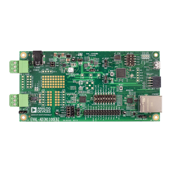
EVAL-ADIN1100EBZ BOARD PHOTOGRAPH
PLEASE SEE THE LAST PAGE FOR AN IMPORTANT
WARNING AND LEGAL TERMS AND CONDITIONS.
Arrow.com.
Downloaded from
ADIN1200 Ethernet PHY
ADIN1100
features
ADuCM4050
microcontroller
2
maximum,
®
7 (or later version) with USB
User Guide | EVAL-ADIN1100
DOCUMENTATION NEEDED
ADIN1100 data sheet
►
GENERAL DESCRIPTION
The EVAL-ADIN1100EBZ is a flexible platform enabling quick eval-
uation of the ADIN1100 robust, low power 10BASE-T1L PHY. The
EVAL-ADIN1100EBZ provides 10 Mbps single pair Ethernet (SPE)
connections with devices across 1.7 km of cable.
The evaluation board offers two modes of operation for maximum
flexibility. Connected to a PC via USB port, the full set of ADIN1100
register settings and features such as link quality monitoring and
diagnostics can be accessed with the ADIN1100 GUI software.
Alternatively, the EVAL-ADIN1100EBZ board can operate in stand-
alone mode where it is configured by setting hardware configuration
links and switches. On-board LEDs provide status indication.
The ADIN1100 data (MII, RMII, and RGMII) and management
(MDIO) interfaces are accessible on header connectors for easy
connection to an external host controller.
A small prototyping area and test points are provided for experi-
mentation with alternative cable connection topologies including
isolation transformers and/or power coupling inductors.
The platform can perform as a 10BASE-T1L to 10BASE-T media
converter. This feature enables connection to other devices (dem-
onstration boards or custom prototypes) with a 10BASE-T1L Ether-
net port and conversion of the data to standard Ethernet, which is
accessible via the RJ45 connector.
Full details about the ADIN1100 are available in the ADIN1100
data sheet, which must be consulted when using the EVAL-
ADIN1100EBZ.
Figure 1.
UG-2011
Rev. 0 | 1 of 11
Advertisement
Table of Contents

Subscribe to Our Youtube Channel
Related Manuals for Analog Devices EVAL-ADIN1100


Summary of Contents for Analog Devices EVAL-ADIN1100
-
Page 1: Features
User Guide | EVAL-ADIN1100 UG-2011 Evaluating the ADIN1100 Robust, Industrial, Low Power 10BASE-T1L PHY, and Media Converter to 10BASE-T with ADIN1200 Ethernet PHY FEATURES DOCUMENTATION NEEDED User friendly access to all ADIN1100 features ADIN1100 data sheet ► ► GUI software on PC or standalone hardware configured opera- ►... -
Page 2: Table Of Contents
User Guide EVAL-ADIN1100 TABLE OF CONTENTS Features..............1 Hardware Configuration Setup......5 Evaluation Kit Contents......... 1 Microcontroller Modes of Operation....7 Equipment Needed..........1 Software..............8 Software (Optional)..........1 Driver for USB COM Port........8 Documentation Needed.........1 Serial COM Port and Terminal Settings....8 General Description..........1... -
Page 3: Overview
User Guide EVAL-ADIN1100 OVERVIEW Table 1 for detailed descriptions of the components labeled in Figure Figure 2. Detailed View of the EVAL-ADIN1100EBZ Table 1. Component Descriptions Reference Designator Description Jumper for board power selection. J2, J3 Jumpers for local power: 3.3 V and 1.8 V. Keep J2 and J3 inserted. - Page 4 User Guide EVAL-ADIN1100 OVERVIEW Figure 3. EVAL-ADIN1100EBZ Simplified Block Diagram analog.com Rev. 0 | 4 of 11 Arrow.com. Arrow.com. Arrow.com. Arrow.com. Downloaded from Downloaded from Downloaded from Downloaded from...
-
Page 5: Hardware
User Guide EVAL-ADIN1100 HARDWARE POWER SUPPLIES GROUND CONNECTIONS The EVAL-ADIN1100EBZ can be powered by a power supply with The EVAL-ADIN1100EBZ board has an Earth node. Although this an output voltage between 5 V dc and 32 V dc connected via the... - Page 6 User Guide EVAL-ADIN1100 HARDWARE Table 3. Default Firmware Mode Configuration, S403 (Labeled uC CFG) Switch Position Switch Name Default Position CFG_0 CFG_1 CFG_2 CFG_3 Mode 15 media converter (default positions for S403 when shipped). All switches off. See Table Table 4. ADIN1100 Hardware Configuration, S201 (Labeled HW CFG)
-
Page 7: Microcontroller Modes Of Operation
User Guide EVAL-ADIN1100 HARDWARE Therefore, to change the mode of operation, the board must be MICROCONTROLLER MODES OF OPERATION reset by pressing the S501 reset button or by applying a power The EVAL-ADIN1100EBZ can be used in various modes of opera- cycle after changing the position of the S403 DIP switch. -
Page 8: Software
The examples in the following sections were captured using Com- as link quality monitoring and diagnostics can be accessed with the puPhase Termite. ADIN1100 GUI software, available from Analog Devices, Inc. INITIAL WELCOME MESSAGE Alternatively, the ADIN1100 and ADIN1200 registers, 10BASE‑T1L... -
Page 9: Status And Diagnostics
User Guide EVAL-ADIN1100 SOFTWARE in hex. phystatus 'mdiowr_cl45 ,,' ADIN1200 Link is Up, * MDIO (Clause 45) read from Phy, all numbers ADIN1100 Link is Up, Master, 2.4 V in hex. MSE -37.2 dB Rx 0, Err 0 'mdiord_cl45 ,'... -
Page 10: Microcontroller Firmware Update
User Guide EVAL-ADIN1100 MICROCONTROLLER FIRMWARE UPDATE ® ® The Arm Cortex ADuCM4050 microcontroller (U401) is pro- If using a terminal program for communicating with the EVAL- grammed before shipping the EVAL-ADIN1100EBZ board. There- ADIN1100EBZ board, either disconnect it by releasing the COM... -
Page 11: Notes
Evaluation Board until you have read and agreed to the Agreement. Your use of the Evaluation Board shall signify your acceptance of the Agreement. This Agreement is made by and between you (“Customer”) and Analog Devices, Inc. (“ADI”), with its principal place of business at Subject to the terms and conditions of the Agreement, ADI hereby grants to Customer a free, limited, personal, temporary, non-exclusive, non-sublicensable, non-transferable license to use the Evaluation Board FOR EVALUATION PURPOSES ONLY.
Need help?
Do you have a question about the EVAL-ADIN1100 and is the answer not in the manual?
Questions and answers