Anritsu Field Master MS2080A User Manual
Handheld rf spectrum analyzer
Hide thumbs
Also See for Field Master MS2080A:
- Measurement manual (172 pages) ,
- Measurement manual (152 pages) ,
- Measurement manual (158 pages)
Table of Contents
Advertisement
Quick Links
Advertisement
Table of Contents

Related Manuals for Anritsu Field Master MS2080A


Summary of Contents for Anritsu Field Master MS2080A
- Page 1 User Guide Field Master™ MS2080A Handheld RF Spectrum Analyzer MS2080A-0704 9 kHz to 4 GHz (Option 704) Anritsu Company Part Number: 10580-00483 490 Jarvis Drive Revision: A Morgan Hill, CA 95037-2809 Published: October 2022 Copyright 2022 Anritsu Company...
- Page 2 Anritsu Company. Export Management The Anritsu products identified herein and their respective manuals may require an Export License or approval by the government of the product country of origin for re-export from your country. Before you export these products or any of their manuals, please contact Anritsu Company to confirm whether or not these items are export-controlled.
- Page 3 Table of Contents MS2080A UG PN: 10580-00483 Rev. A Contents-1...
-
Page 4: Table Of Contents
Contacting Anritsu for Sales and Service ........ - Page 5 Table of Contents (Continued) 2-10 Settings Menu............. 2-20 Display Settings.
- Page 6 Introduction ..............B-1 Exporting a Software Configuration File .
-
Page 7: Chapter 1-General Information
Field Master Series HIPM Measurement Guide 10580-00493 Field Master Series CAA Measurement Guide For additional information and literature covering your product, visit the product page of your instrument and select the Library tab: http://www.anritsu.com/en-us/test-measurement/products/ms2080a MS2080A UG PN: 10580-00483 Rev. A... -
Page 8: Document Conventions
1-1 Introduction General Information Document Conventions The following conventions are used throughout the MS2080A documentation set. Instrument Identification When identifying a frequency option for the MS2080A, that option number is appended after the model number; example: MS2080A-0704. User Interface The MS2080A user interface consists of menus, buttons, toolbars, and dialog boxes. User Interface Navigation Elements in navigation paths are separated as follows: MARKER >... -
Page 9: Instrument Description
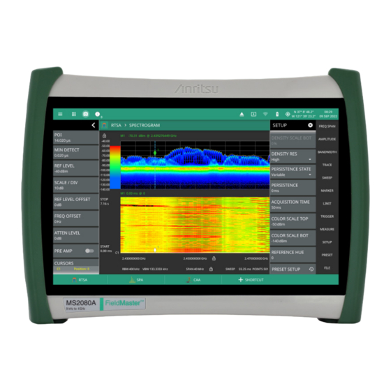
General Information 1-2 Instrument Description Instrument Description The MS2080A Field Master is a synthesizer-based handheld RF spectrum analyzer that provides quick and accurate measurement results. The instrument is designed for monitoring, measuring, and analyzing signal environments. Measurements can easily be made by using the main instrument functions: frequency, span, amplitude, and bandwidth. -
Page 10: Instrument Care And Preventive Maintenance
1-3 Instrument Care and Preventive Maintenance General Information Instrument Care and Preventive Maintenance Instrument care and preventive maintenance consist of proper operation in a suitable environment, occasional cleaning of the instrument, and inspecting and cleaning the RF connectors and all accessories before use. Clean the instrument with a soft, lint-free cloth dampened with water or water and a mild cleaning solution. -
Page 11: Esd Caution
Calibration and Verification The Field Master comes fully calibrated from the factory and there are no field-adjustable components. Anritsu recommends annual calibration and performance verification by local Anritsu service centers. Accredited calibration to ISO17025 and ANSI/NCSL Z540-1 are available and can include a calibration certificate, test report, and uncertainty data. - Page 12 1-5 Contacting Anritsu for Sales and Service General Information PN: 10580-00483 Rev. A MS2080A UG...
-
Page 13: Chapter 2-Instrument Overview
Chapter 2 — Instrument Overview Introduction This chapter provides an overview of the Anritsu MS2080A Field Master. It describes the instrument hardware features, touch screen display, general system settings, GUI overview and instrument configurations, and the connector panels. Instrument Front Panel The Field Master uses a LCD touch screen for data input. -
Page 14: Connector Panels
2-3 Connector Panels Instrument Overview Connector Panels The MS2080A Field Master uses the top connector panel to provide for all physical IO. The top panel uses a variety of connector types intended for their purpose. RF Connectors The main RF input connector is Type N. It is a ruggedized 50 female connector. Additional IO is provided with the SMA style connectors. - Page 15 Instrument Overview 2-3 Connector Panels 4. External Power: This is a 2.5 mm by 5.5 mm barrel connector, 15 VDC, 5 A, center positive. The external power connector is used to power the unit and for battery charging. When using the AC-DC Adapter, always use a three-wire power cable that is connected to a Warning three-wire power line outlet.
-
Page 16: Tilt Bail Stand
2-4 Tilt Bail Stand Instrument Overview Tilt Bail Stand The attached tilt bail can be used for desktop operation. The tilt bail provides a backward tilt for improved stability and air flow. To deploy the tilt bail, pull the bottom of the tilt bail away from the back of the instrument. -
Page 17: Battery Information
If the adapter plug becomes hot to the touch during operation, discontinue use immediately. Anritsu Company recommends removing the battery for long-term storage of the instrument. The batteries will charge at a faster rate when the instrument is turned off. -
Page 18: Replacing The Battery
2-5 Battery Information Instrument Overview Replacing the Battery The battery can be replaced without the use of tools. The battery compartment door is located on the lower left side of the instrument (when you are facing the measurement display). To remove the battery: Push in and slide the battery door tab to the left to remove the battery access door. -
Page 19: Turning On The Ms2080A Field Master
15 VDC source (which will simultaneously charge the battery). This can be achieved with either the Anritsu AC-DC adapter or the automotive power adapter, which can be purchased as an optional accessory. Refer to the instrument Technical Data Sheet for more options and accessories. The instrument can also be charged for up to six hours using an Extended Power Pack that is sold separately. -
Page 20: Gui Overview
2-7 GUI Overview Instrument Overview GUI Overview The MS2080A Field Master software controls all instrument functions. The software runs locally on the instrument and primary operation is through the touch screen display. The figure below identifies the main display areas, which are each described in more detail later in this chapter. 1. -
Page 21: Operating The Touch Screen
Instrument Overview 2-7 GUI Overview Operating the Touch Screen Field Master uses common touch gestures to achieve a variety of operations. These include interactions on hot areas by pressing, double pressing (or tapping), dragging, and pinching. Single Press: Most controls require a single press or tap. -
Page 22: Title Bar
2-7 GUI Overview Instrument Overview Title Bar The title bar is located at the top of the interface screen. It displays icons that provide access to information and user actions as described below. All of the icons are active and will open the appropriate menu or item when touched. - Page 23 Instrument Overview 2-7 GUI Overview Common GUI Controls In addition to the touch gestures described in the previous section, the following lists the most common controls that you will encounter when working with the Field Master. The 3-line icon provides quick access to system information, settings, file management, and built-in diagnostic tools.
-
Page 24: Data Entry
2-7 GUI Overview Instrument Overview Gesture lock and unlock icons indicate when the drag and pinch gestures have been toggled on or off. Refer to Gestures menu the instrument measurement guide. Reference Level padlock icons are used to lock/unlock the reference level of the graticule. - Page 25 Instrument Overview 2-7 GUI Overview Selection Lists Some parameters and instrument functions are selectable from a list. These list boxes display the available selections and value limits as applicable. Use the touch screen to scroll through the list and select the desired entry.
-
Page 26: Scroll Indication
2-7 GUI Overview Instrument Overview Scroll Indication In some cases, menus, status panels, or other lists contain more information than can be displayed in the available area. In these cases, the top or bottom of the panel will have a fade-to-white appearance as shown below. - Page 27 Instrument Overview 2-7 GUI Overview Text Entry and EZ Keyboard When an instrument function requires you to enter text, such as entering an Ethernet hostname or IP address, a touch screen alphabetic keyboard is displayed. See Figure 2-12. Press the “?123” key to switch to the digits and symbols keyboard.
- Page 28 2-7 GUI Overview Instrument Overview To change a key’s value: Press the pencil (edit) key. The EZ keys will become highlighted. Figure 2-14. Touch Screen EZ Keyboard Press the key to be edited. This will display the standard keyboard for entering a new EZ key value. Figure 2-15.
-
Page 29: Selecting The Analyzer
Instrument Overview 2-8 Selecting the Analyzer Selecting the Analyzer The instrument analyzers are selected from the 9-dot icon. To select an analyzer, press the 9-dot icon in the title bar to display the available analyzers, illustrated in Figure 2-16. Simply touch the desired icon to load the new analyzer. -
Page 30: System Menu
2-9 System Menu Instrument Overview System Menu The System menu identifies the instrument model and serial number. HOSTNAME/IP ADDRESS: Displayed only on the MS2080A PC application. This field is used to specify the IP address or hostname of an instrument that is connected to the network. -
Page 31: Notifications
Instrument Overview 2-9 System Menu Notifications The notification area is where all dynamic notifications are presented. These notifications are generally information messages to the user and not hardware failure messages. Refer to “Self Test” on page 2-45 Appendix A, “Instrument Messages and Troubleshooting” for more diagnostic information. -
Page 32: 2-10 Settings Menu
2-10 Settings Menu Instrument Overview 2-10 Settings Menu The system settings menu provides access to all instrument system-level settings such as network, GPS/GNSS, date and time, and display. The system settings menu provides access to all instrument system-level settings such as network, GPS/GNSS, date and time, and display. DISPLAY: Opens the “Display Settings”. -
Page 33: Display Settings
Instrument Overview 2-10 Settings Menu Display Settings The DISPLAY settings allow you to adjust the display brightness, choose the display color scheme and to view or hide shortcuts to the saved application settings. Brightness The BRIGHTNESS option consists of a slider to adjust the screen brightness, in addition to selecting the amount of idle time before the screen automatically dims to conserve battery life. - Page 34 2-10 Settings Menu Instrument Overview Theme Under THEME option press COLOR SCHEME drop-down menu and select either Default, Light, Black on White or Night Vision to set the display color scheme of your choice. If the THEME is set to Light it may be more suitable for viewing in bright ambient conditions.
- Page 35 Instrument Overview 2-10 Settings Menu Figure 2-23. Black on White Theme Display Setting Figure 2-24. Night Vision Theme Display Setting MS2080A UG PN: 10580-00483 Rev. A 2-23...
- Page 36 2-10 Settings Menu Instrument Overview Shortcuts Under the SHORTCUTS option, toggle the HIDE SHORTCUTS button to view or hide the shortcuts. Press + SHORTCUT button located at the bottom left of the display screen to create or save specific settings of an application.
- Page 37 Instrument Overview 2-10 Settings Menu Enter the shortcut name which is optional, and press CONTINUE. Figure 2-27. Add Shortcut Dialog Press the newly created shortcut to recall the saved setup file. To delete all the shortcuts, press SYSTEM MENU (3-line icon), go to SETTINGS menu, press DISPLAY settings and press CLEAR ALL button at the bottom right of the instrument’s display.
-
Page 38: Sound Settings
2-10 Settings Menu Instrument Overview Sound Settings The SOUND settings allow you to adjust the SYSTEM VOLUME or MUTE ALL of the instrument sounds. The system volume may affect other volume settings found in various setup menus. Figure 2-29. Sound Settings Network Settings The MS2080A uses Ethernet or WLAN (Wi-Fi) to communicate remotely with a controller. - Page 39 Instrument Overview 2-10 Settings Menu • The remote program may connect to the instrument IP address or to its HOSTNAME (Ethernet only). If using DHCP instead of a static IP, using the HOSTNAME may be more reliable for finding an instrument on a network.
-
Page 40: Ethernet Settings
2-10 Settings Menu Instrument Overview The instrument IP address and its HOSTNAME are set via the System menu (upper left corner) and accessing the ETHERNET or WIFI settings menu. Wi-Fi does not support connections using HOSTNAME; use IP addressing to establish a wireless Note network connection. -
Page 41: Wifi Settings
Instrument Overview 2-10 Settings Menu WiFi Settings Refer to “Network Settings” on page 2-26 for general network setup and information. Access the System menu (3-line icon in the upper left corner). Press SETTINGS to access the instrument settings menu, then select WIFI to display the current network settings (IP address, HOSTNAME, etc.). -
Page 42: Gps/Gnss Settings (Option 31)
2-10 Settings Menu Instrument Overview GPS/GNSS Settings (Option 31) The MS2080A Field Master is available with a built-in global positioning receiver feature (Option 31) that can provide latitude, longitude, altitude, and UTC timing information. This option also enhances frequency reference oscillator accuracy. When the global positioning receiver is actively locked to satellites, this information is saved with all saved measurements. - Page 43 Instrument Overview 2-10 Settings Menu When the GPS receiver has established a “good fix”, the GPS icon is displayed with a center dot and the following information is kept updated: • Fix status • Tracked satellites • Latitude • Longitude •...
-
Page 44: Screenshot Setup
2-10 Settings Menu Instrument Overview Screenshot Setup Access the System menu (3-line icon in the upper left corner). Press SETTINGS to access the instrument settings menu, then select SCREENSHOT to open the screenshot setup menu. Figure 2-33. Screenshot Setup Screenshot setup lets you configure the following: •... -
Page 45: Language Settings
Instrument Overview 2-10 Settings Menu Language Settings Follow the steps below to access language settings in order to change a selected display language Access the System menu (3-line icon in the upper left corner). Press SETTINGS to access the instrument settings menu, then select LANGUAGE to open the language menu. -
Page 46: Date Time Settings
2-10 Settings Menu Instrument Overview Date Time Settings Access the System menu (3-line icon in the upper left corner). Press SETTINGS to access the instrument settings menu, then select DATE TIME to display the current date and time settings. Figure 2-35. Date Time Settings The Date Time setup lets you set the current date and time and the time zone. -
Page 47: Port Setup
Instrument Overview 2-10 Settings Menu Port Setup The Port Setup menu allows you to configure the external ports. Bias Voltage Bias Voltage setup provides controls to set the voltage level and to monitor the precise voltage and current, and trip state. Access the System menu (3-line icon in the upper left corner). - Page 48 2-10 Settings Menu Instrument Overview Reference and Trigger The reference and trigger setup provides controls to set the functionality of the configurable top panel reference and trigger ports. Access the System menu (3-line icon in the upper left corner). Press SETTINGS to access the instrument settings menu, then select PORT SETUP > REF / TRIG to display the top panel reference and trigger port settings.
-
Page 49: Options Settings
Instrument Overview 2-10 Settings Menu Options Settings To view the installed options, follow the steps below: Access the System menu (3-line icon in the upper left corner). Press SETTINGS to access the instrument settings menu. Select OPTIONS to view the list of currently installed options in the left tab, and available options in the right tab. - Page 50 2-10 Settings Menu Instrument Overview Once a time limited option is activated, the 90-day time period begins countdown and cannot be Caution halted. Ensure you intend to activate the option before pressing Activate. When time-limited options are installed but not yet active, press the ACTIVATE button to activate the option and begin the 90-day trial.
-
Page 51: Maps Settings (Option 431)
Instrument Overview 2-10 Settings Menu Maps Settings (Option 431) Map settings are available when Option 431, Coverage Mapping is installed. Maps settings are used to delete map tiles from instrument memory. Refer to Coverage Mapping section of SPA measurement guide (10580-00447). -
Page 52: Reset Settings
2-10 Settings Menu Instrument Overview Reset Settings Access the System menu (3-line icon in the upper left corner). Press SETTINGS to access the instrument settings menu. Select RESET to open the Reset menu. Figure 2-42. Reset Settings The following reset options are available: SETTINGS RESET •... -
Page 53: File Management
Instrument Overview 2-11 File Management 2-11 File Management Access the System menu (3-line icon in the upper left corner). Press FILES to access the instrument file management menu. Figure 2-43. File Management Menu MS2080A UG PN: 10580-00483 Rev. A 2-41... -
Page 54: File Locations
2-11 File Management Instrument Overview File Locations Displays the available memory locations. Touch the location that you want to access and the available files will be displayed on the right side. You can touch the column headers to change the sort order. File Management Operations All file operations are selected via the following icons: 3-Dots... -
Page 55: Previewing Screenshots
Instrument Overview 2-11 File Management Previewing Screenshots While in File Manager, you can preview screenshots on the instrument display simply by touching the screenshot file name. While the preview is displayed, you can use the controls to: • Cycle forward and backward through each screenshot in the directory. •... -
Page 56: 2-12 Diagnostics
2-12 Diagnostics Instrument Overview 2-12 Diagnostics Access the System menu (3-line icon in the upper left corner). Press DIAGNOSTICS to access the instrument diagnostics menu, then select the diagnostic menu that you wish to open. BATTERY: Opens Battery Information. EVENT LOG: Opens the Event Log. -
Page 57: Self Test
The self test results can be saved to a file for future reference. Refer to Appendix A, “Instrument Messages and Troubleshooting” for more information. Figure 2-49. Self Test Service Mode The service mode is for Anritsu customer service use only. Figure 2-50. Service Mode MS2080A UG PN: 10580-00483 Rev. A 2-45... -
Page 58: 2-13 Tools Menu
2-13 Tools Menu Instrument Overview 2-13 Tools Menu Access the System menu (3-line icon in the upper left corner). Select TOOLS to access the instrument tools menu, then select the tool menu that you wish to open. MAP TOOL: Opens Map Tool. Refer to Map Tool under Coverage Mapping section of SPA measurement guide (10580-00447). -
Page 59: 2-14 Software Update
2-14 Software Update 2-14 Software Update To update your Anritsu instrument software, use a high quality USB memory device with at least 1 GB of free space and FAT32 file system format. Insert the USB memory device into your PC or laptop. - Page 60 2-14 Software Update Instrument Overview Verify the Software Update Once the software update is complete, power off the MS2080A. Power on the MS2080A. Press the System menu icon (3-line icon) from the MS2080A to display the System Menu. Select the System Information menu (see Figure...
-
Page 61: Appendix A-Instrument Messages And Troubleshooting
Troubleshooting Introduction This appendix provides a list of instrument messages and their meaning and procedures for a full system recovery. If any error condition persists, contact your local Anritsu Service Center (http://www.anritsu.com/contact-us). Field Master displays the following message types: •... -
Page 62: Self-Test Messages
A-2 Self-Test Messages Instrument Messages and Troubleshooting Self-Test Messages Field Master has built-in diagnostics that allow you to run a built-in self test. The test results can be viewed on the screen and saved to a log file. To run self test, use the 3-line menu to access DIAGNOSTICS, then select SELF TEST and RUN SELF TEST. - Page 63 Thermal Sensor 2 (Final IF): 43.50 C (expected: 35.00 V, tolerance: 90.00 C) If any self test fails, try resetting the instrument with a RESET ALL and reboot, and run the test again. If the condition persists, contact your local Anritsu Service Center (http://www.anritsu.com/contact-us). MS2080A UG...
-
Page 64: File Management Messages
A-3 File Management Messages Instrument Messages and Troubleshooting File Management Messages File management functions (accessed by via System menu (3-line icon) > FILES) are used to organize, copy, and rename files. The following messages are displayed in a persistent dialog when using the file manager features. -
Page 65: Informational Messages
Instrument Messages and Troubleshooting A-4 Informational Messages Informational Messages Audio must be turned on to record. In Toolbar, Not Logged, Transient Battery Over Charge Temperature. In Toolbar, Not Logged, Persistent Cannot start measurement without a connected Antenna. In Toolbar, Not Logged, Persistent Calibration abort is not allowed. - Page 66 A-4 Informational Messages Instrument Messages and Troubleshooting File Recall Failed In Toolbar, Not Logged, Transient File Recalled Successfully In Toolbar, Not Logged, Transient File Save Failed In Toolbar, Not Logged, Transient File Saved Successfully In Toolbar, Not Logged, Transient File successfully saved as: filename When saving a file (e.g., trace, setup) File <filename>...
- Page 67 Instrument Messages and Troubleshooting A-4 Informational Messages Initializing the USB VNA... In Toolbar, Not Logged, Transient Input greater than DMax: <value> In Toolbar, Not Logged, Transient IQ STREAM - Sweep paused while IQ stream is in progress In Toolbar, Not Logged, Persistent IQ CAPTURE - Sweep paused while IQ capture is in progress In Toolbar, Not Logged, Persistent Language successfully updated to X...
- Page 68 A-4 Informational Messages Instrument Messages and Troubleshooting No USB CAA HW connected In Toolbar, Not Logged, Persistent No USB Site Master is detected. Please connect device to continue. In Toolbar, Not Logged, Transient No application loaded. Factory reset required In Toolbar, Logged, Persistent <model>...
- Page 69 Instrument Messages and Troubleshooting A-4 Informational Messages Recording Complete. File saved as <filename> In Toolbar, Logged, Transient Remove any RF input signal to the external sensor Pop-up, Not Logged, Transient RF Attenuation Auto must be OFF or Reference Level must be below -40dBm to enable PreAmp In Toolbar, Logged, Transient Successfully concatenated <N>...
- Page 70 A-4 Informational Messages Instrument Messages and Troubleshooting The selected mode is not yet available When an unavailable mode is selected. Transmission (Ext. Sensor) measurement requires supported USB sensor In Toolbar, Not Logged, Persistent USB drive <name> ejected In Toolbar, Not Logged, Transient Zeroing.
-
Page 71: Warning Messages
Instrument Messages and Troubleshooting A-5 Warning Messages Warning Messages ADC Overrange In Toolbar, Logged, Persistent Antenna information invalid In Toolbar, Not Logged, Persistent Battery Fault In Toolbar, Logged, Transient Battery level is critically low. Automatic shutdown is imminent Popup, Logged, Persistent Battery level low Popup, Logged, Persistent Battery Low warning... - Page 72 A-5 Warning Messages Instrument Messages and Troubleshooting Failed to save screenshot. Device may be full. When saving a screenshot fails. IF Gain Calibration is off In Toolbar, Logged, Persistent IF Shape Calibration is off In Toolbar, Logged, Persistent Invalid frequency setup for this antenna In Toolbar, Logged, Transient Limit recall initiated When a limit setup file is selected for recall.
- Page 73 Instrument Messages and Troubleshooting A-5 Warning Messages Shutdown Battery Level Reached Pop-up Window, Logged, Persistent: Requires User Intervention Sent after a Battery Low warning. A shutdown will occur when the battery charge is or below 5%. Shutdown Temperature Reached Popup, Logged, Persistent Simulated Test Signal data being displayed In Toolbar, Logged, Persistent Spectrogram view not available...
-
Page 74: Error Messages
A-6 Error Messages Instrument Messages and Troubleshooting Error Messages Antenna disconnected. Terminating measurement In Toolbar, Logged, Transient ALC Unlevel Error (X) @ Y Hz In Toolbar, Logged, Transient. X represents the ALC that failed and Y represents the specific frequency value at which the failure occurred. - Page 75 Instrument Messages and Troubleshooting A-6 Error Messages Out of Range In Toolbar, Not Logged, Transient Options <value> are not valid for the currently installed firmware version. The device might not function properly In Toolbar, Logged, Persistent PLL Unlock Error (X) In Toolbar, Logged, Persistent.
- Page 76 A-6 Error Messages Instrument Messages and Troubleshooting Options listed <value> are not valid. Restored to previous options In Toolbar, Not Logged, Transient. This error may occur when upgrading options from an options upgrade file fails due to an invalid option configuration. The options will be restored to the previous options numbers.
-
Page 77: System Recovery
Instrument Messages and Troubleshooting A-7 System Recovery System Recovery This section can be referred to in the event the MS2080A does not boot properly and the normal attempts to restart the instrument have failed. Introduction If the MS2080A fails to boot properly, a second boot attempt will load a recovery menu as shown in Figure A-1. - Page 78 A-7 System Recovery Instrument Messages and Troubleshooting The Recovery Mode menu (Figure A-2) shows instrument information and provides a variety of recovery options in ascending invasive order: Press REBOOT to reboot the instrument without any further action. Save all internal user files and logs by inserting a USB device and press the EXPORT button. Refer to “Reset”...
-
Page 79: Reset
Instrument Messages and Troubleshooting A-7 System Recovery Reset The recovery RESET dialog is shown in Figure A-3. Here you can reset the MS2080A from the choices shown. In rare cases, system, internal, or other user files may interfere with instrument operation, so choosing to delete this data in that order may resolve a problem. -
Page 80: Install Sw To Slot X
A-7 System Recovery Instrument Messages and Troubleshooting Install SW to SLOT X The recovery mode shows two slots (A and B). These slots contain different system software packages that are installed. Each slot contains the following information: • Slot name (A,B): Boot version package (A or B). •... -
Page 81: Udp Discovery Tool Firewall Settings
Instrument Messages and Troubleshooting A-8 UDP Discovery Tool Firewall Settings UDP Discovery Tool Firewall Settings Follow the instructions below if the Discovery tool is not responding: Go to Control Panel and open Windows Defender Firewall settings. Click Allow an app or feature through Windows Defender Firewall. Figure A-5. - Page 82 A-8 UDP Discovery Tool Firewall Settings Instrument Messages and Troubleshooting Find fieldmaster_base in the list of apps, and make sure that the fieldmaster_base box and Domain box are checked. Private and Public boxes may also need to be checked depending on where the instruments are on the network.
-
Page 83: System Override
Instrument Messages and Troubleshooting A-9 System Override System Override In the event that the instrument does not respond to SCPI commands (due to circumstances like a long sweep used in conjunction with *OPC?) and needs to be reset remotely, the system override feature can be used. System override can be accessed through TCP port 8001 of the instrument. - Page 84 A-9 System Override Instrument Messages and Troubleshooting A-24 PN: 10580-00483 Rev. A MS2080A UG...
-
Page 85: Appendix B-Software Option Upgrades
Importing Software License Importing a new license file: After receiving a new license file from Anritsu, place the file on the USB memory device in the top (root) level, not in any directory. Open the System menu from the upper left 3-line icon. - Page 86 B-3 Importing Software License Software Option Upgrades PN: 10580-00483 Rev. A MS2080A UG...
-
Page 87: Appendix C-Ms2080A Pc Software
Appendix C — MS2080A PC Software Introduction The MS2080A PC software provides remote access to a network connected instrument and displays the same MS2080A user interface, instrument controls, and live measurement data on the computer screen. The software also allows you to load measurement and setup data from saved files and then perform measurement analysis on the recalled traces, even when instrument hardware is not available or is not connected to the PC by using the localhost (refer to Section C-4 “Connecting to the MS2080A or... -
Page 88: Installation
C-3 Installation MS2080A PC Software Installation Download the MS2080A software from the product page: http://www.anritsu.com/en-us/test-measurement/products/ms2080a Launch the MS2080A executable file and follow the on-screen instructions after selecting YES to the User Account Control dialog. Figure C-1. MS2080A Installation PN: 10580-00483 Rev. A... -
Page 89: Connecting To The Ms2080A Or Localhost
MS2080A PC Software C-4 Connecting to the MS2080A or Localhost Connecting to the MS2080A or Localhost Connecting to a networked instrument or to the localhost is established via the system menu. If connecting to an instrument, the instrument must first be connected to the network via Ethernet or Wi-Fi and the IP address of the instrument must be known. -
Page 90: Measurement Setup Parameters
C-5 Working with the Localhost MS2080A PC Software • Trace files will be recalled into a "HOLD" state, just like they would be on an instrument. This means that if the user changes the span, center frequency, or other settings that invalidate the data, all trace data will be cleared from the screen. -
Page 91: File (File Management
MS2080A PC Software C-6 FILE (File Management) MEASURE Some measurements can be selected when the appropriate data is recalled. For example, a an Channel Power, OBW, and ACP measurements can be applied to a normal spectrum trace. SETUP Setup parameters for Channel Power, OBW, and ACP can be adjusted. PRESET Preset functions will preset the selected items and suppressed recalled measurement data. - Page 92 C-6 FILE (File Management) MS2080A PC Software PN: 10580-00483 Rev. A MS2080A UG...
- Page 94 Anritsu Company 490 Jarvis Drive Anritsu utilizes recycled paper and environmentally conscious inks and toner. Morgan Hill, CA 95037-2809 http://www.anritsu.com...
Need help?
Do you have a question about the Field Master MS2080A and is the answer not in the manual?
Questions and answers