
Subscribe to Our Youtube Channel
Related Manuals for Kramer WP-28


Summary of Contents for Kramer WP-28
-
Page 1: User Manual
Kramer Electronics, Ltd. USER MANUAL Models: WP-27, Component/CV/YC – S/PDIF/Analog Transmitter WP-28, Component/CV/YC – S/PDIF/Analog Receiver... -
Page 2: Table Of Contents
Table 1: WP-27 Component/CV/YC – S/PDIF/Analog Transmitter Front Panel Features 6 Table 2: WP-27 Component/CV/YC – S/PDIF/Analog Transmitter Rear Panel Features 7 Table 3: WP-28 Component/CV/YC – S/PDIF/Analog Receiver Front panel Features Table 4: WP-28 Component/CV/YC – S/PDIF/Analog Receiver Rear Panel Features... -
Page 3: Introduction
2 A separate power supply is included with each product 3 Download up-to-date Kramer user manuals from the Internet at this URL: http://www.kramerelectronics.com 4 The complete list of Kramer cables is on our Web site at http://www.kramerelectronics.com Introduction , which are clearly defined... - Page 4 Getting Started KRAMER: SIMPLE CREATIVE TECHNOLOGY...
-
Page 5: Overview
3 The audio signal is outputted to both outputs simultaneously 4 The WP-27 and WP-28 do not perform any video signal format conversion. A composite video source would need to be routed to a composite video output or an s-Video source would need to be routed to an s-Video output. Similarly, a... -
Page 6: About The Power Connect Feature
An analog audio input A digital audio input (S/PDIF) An AUDIO INPUT selector button A CAT5 output for signal transmission to the WP-28 The WP-28 Receiver includes: An s-Video (Y/C) output on a 4p connector A composite video (CV) output on an RCA connector... -
Page 7: Shielded Twisted Pair (Stp) / Unshielded Twisted Pair (Utp)
(often associated with low quality cables) Avoiding interference from neighboring electrical appliances that may adversely influence signal quality and positioning your WP-27 and/or WP-28 in a location free from moisture and away from excessive sunlight and dust Caution Warning... -
Page 8: Your Wp-27 Component/Cv/Yc - S/Pdif/Analog Transmitter
ANALOG 3.5mm Mini Jack Connector 1 Figure 1 illustrates the WP-27 version for the USA. There is also a similar version available for Europe Your WP-27 / WP-28 Function For fastening the wall plate in place Connect to the s-Video source Connect to the composite video source Push in to select COMP (component video);... -
Page 9: Your Wp-28 Component/Cv/Yc - S/Pdif/Analog Receiver
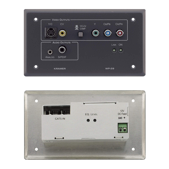
, Figure 4, Table 3 and Table 4 define the WP-28: Figure 3 Figure 3: WP-28 Component/CV/YC – S/PDIF/Analog Receiver Front Panel 1 Figure 3 illustrates the WP-28 version for the USA. There is also a similar version available for Europe Your WP-27 / WP-28 Function... -
Page 10: Figure 4: Wp-28 Component/Cv/Yc - S/Pdif/Analog Receiver Rear Panel
Table 3: WP-28 Component/CV/YC – S/PDIF/Analog Receiver Front panel Features Feature Holes (4) Y/C 4p Connector CV RCA Connector Y/C-CV COMP Selector Button Y RCA Connector RCA Connector RCA Connector ON LED LINK LED S/PDIF RCA Connector ANALOG 3.5mm Mini Jack Connector Figure 4: WP-28 Component/CV/YC –... -
Page 11: Connecting The
4 Thus selecting the digital audio input 5 Thus selecting the component video output 6 If you cannot connect the power to both the WP-27 and WP-28, you can just connect the power to the WP-28 Connecting the WP-27 / WP-28... -
Page 12: Figure 5: Connecting The
Connecting the WP-27 / WP-28 7. If required, on the WP-28, adjust the equalization and audio level. Figure 5: Connecting the WP-27 / WP-28 1 Use a screwdriver to carefully rotate the trimmer, adjusting the appropriate level KRAMER: SIMPLE CREATIVE TECHNOLOGY... -
Page 13: Wiring The Cat 5 Line In / Line Out Rj-45 Connectors
3 and 6 Pair 2 Pair 3 1 and 2 Pair 3 Pair 4 7 and 8 Pair 4 Connecting the WP-27 / WP-28 Figure 6: CAT 5 PINOUT Wire Color Orange / White Orange Green / White Blue Blue / White... -
Page 14: Technical Specifications
Analog/SPDIF: –12dBFS AUDIO: <0.01% WP-27: 12VDC, 200mA WP-28: 12VDC, 300mA WP-27/ WP-28: 12 cm x 7.5 cm x 2.5 cm (4.7" x 2.95" 0.98", W, D, H) WP-27/ WP-28: 0.3 kg (0.67 lbs.) approx Power Supply KRAMER: SIMPLE CREATIVE TECHNOLOGY (Y), 0.3Vpp/75 (C) on a 4p... - Page 15 EXCLUSION OF DAMAGES The liability of Kramer for any effective products is limited to the repair or replacement of the product at our option. Kramer shall not be liable for: 1. Damage to other property caused by defects in this product, damages based upon inconvenience, loss of use of the product, loss of time, commercial loss;...
- Page 16 For the latest information on our products and a list of Kramer distributors, visit our Web site: www.kramerelectronics.com, where updates to this user manual may be found. We welcome your questions, comments and feedback. Safety Warning: Disconnect the unit from the power supply before opening/servicing.
Need help?
Do you have a question about the WP-28 and is the answer not in the manual?
Questions and answers