Table of Contents
Advertisement
Quick Links
Advertisement
Table of Contents

Subscribe to Our Youtube Channel
Related Manuals for Kongsberg FLS M3


Summary of Contents for Kongsberg FLS M3
- Page 1 Reference Manual M3 Sonar ® Forward-Looking Multibeam sonar...
- Page 3 Release 1.2 This manual provides you with reference information required to operate and fully understand the commands, menus, modes and options provided by the Kongsberg M3 Sonar FLS Forward Looking Multibeam sonar. 922-20297001/1.2 September 2022 © Kongsberg Maritime Canada Limited...
- Page 4 No part of this document may be copied or reproduced in any form or by any means, and the information contained within it is not to be communicated to a third party, without the prior written consent of Kongsberg Maritime Canada Limited.
-
Page 5: Table Of Contents
Reference Manual Table of contents ABOUT THIS MANUAL ..............7 M3 SONAR FLS ................9 System description ........................ 10 System diagram........................11 System units .......................... 12 Sonar Processor ......................13 Power supply ....................... 13 Sonar Head ........................14 Support information ......................14 GETTING STARTED .............. - Page 6 M3 Sonar FLS Saving and retrieving images ..................45 Recording sonar data ....................45 Playing back a recording ..................... 46 Converting your recording format................47 Converting your recordings to video................49 Saving GeoTiff files..................... 51 Using sonar view overlays ....................54 Measuring distances ....................
- Page 7 Reference Manual Target Marker Export dialog box ................97 Playback Console ......................99 Setup menu ......................... 100 Geo Projection dialog box ..................101 Preferences dialog box ....................103 Head Network Setup dialog box ................106 Head Firmware Configuration dialog box..............109 System Configuration dialog box - Sonar Setup page..........111 System Configuration dialog box - Sensors Setup page..........115 System Configuration dialog box - Rotators Setup page ...........118...
- Page 8 M3 Sonar FLS Interface specifications......................162 Performance specifications ....................165 Mechanical specifications ....................166 Power requirements ......................167 Environmental requirements....................167 Minimum computer requirements..................168 922-20297001/1.2...
-
Page 9: About This Manual
The M3 Sonar FLS Software is included with the M3 Sonar FLS system and updates are available free of charge and can be downloaded from: http://www.kongsberg.com/mesotechsoftware. Software version This M3 Sonar FLS Reference Manual complies with M3 Sonar FLS software version 1.2. - Page 10 We always want to improve our products. We also want our end-user documentation to be comprehensive and relevant. You can help. Please provide comments, suggestions or constructive criticism to our support office. You can contact us by phone at +1 604 464 8144, or by email at: km.support.vancouver@km.kongsberg.com. 922-20297001/1.2...
-
Page 11: M3 Sonar Fls
M3 Sonar FLS M3 Sonar FLS Topics System description, page 10 System diagram, page 11 System units, page 12 Support information, page 14 922-20297001/1.2... -
Page 12: System Description
M3 Sonar FLS Reference Manual System description The M3 Sonar FLS is a high-resolution, multibeam forward-looking sonar. Multibeam sonars have an array of transducers that simultaneously transmits pings (sound pulses) at a specified frequency to cover a large area in less time than a single-beam transducer. -
Page 13: System Diagram
M3 Sonar FLS System diagram The system diagram identifies the main components of a basic M3 Sonar FLS system. Only the main connections between the units are shown. Detailed interface capabilities and power cables are not shown. Sonar Processor Power supply Sonar Head Third-party post-processing software (.mmb data input via Ethernet) 922-20297001/1.2... -
Page 14: System Units
M3 Sonar FLS Reference Manual System units Topics Sonar Processor, page 13 Power supply, page 13 Sonar Head, page 14 922-20297001/1.2... -
Page 15: Sonar Processor
M3 Sonar FLS Sonar Processor In this publication, the computer can also be referred to as the Processor Unit, and vice versa. The Sonar Processor contains the operational software, and offers the user interface that allows you to control the M3 Sonar FLS. It is a vital part of the M3 Sonar FLS system. The Sonar Processor runs the M3 Sonar FLS software that manages communication with the Sonar Head, performs all beamforming and image processing and presents the... -
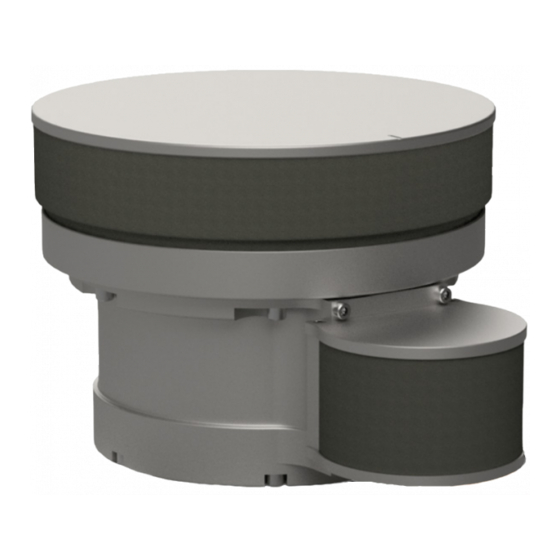
Page 16: Sonar Head
If you require maintenance or repair, contact your local dealer. You can contact us by phone at +1 604 464 8144, or by email at: km.support.vancouver@km.kongsberg.com. If you need information about our other products, visit http://www.km.kongsberg.com/mesotech. On our website you will also find a list of our dealers and distributors. -
Page 17: Getting Started
Getting started Getting started Topics Turning the M3 Sonar FLS system on and off, page 16 Starting normal operation, page 18 922-20297001/1.2... -
Page 18: Turning The M3 Sonar Fls System On And Off
M3 Sonar FLS Reference Manual Turning the M3 Sonar FLS system on and off Topics Turning on the M3 Sonar FLS system, page 16 Turning off the M3 Sonar FLS system, page 17 Turning on the M3 Sonar FLS system To use the M3 Sonar FLS system, you must turn it on. -
Page 19: Turning Off The M3 Sonar Fls System
Getting started Once the program has started, observe that the display presentation fills the entire screen. The software starts up using many of the same settings as the last time you used it. If these settings are acceptable, continue operation. If you wish to alter any of the settings, see the relevant procedures. -
Page 20: Starting Normal Operation
M3 Sonar FLS Reference Manual Starting normal operation Topics Introduction to the basic procedures, page 18 Setting the Sonar Processor to High Performance, page 19 Installing the M3 Sonar FLS software, page 20 Defining the IP address on the computer's network adapter, page 21 Changing the frequency, page 22 Testing operation of the Sonar Head, page 22 Testing the Sonar Head telemetry, page 24... -
Page 21: Setting The Sonar Processor To High Performance
Getting started Setting the Sonar Processor to High Performance To avoid slowdowns or disruptions while running the sonar, ensure your Sonar Processor is using all of its processing power and does not go to sleep. Prerequisites This procedure is made for the Microsoft ®... -
Page 22: Installing The M3 Sonar Fls Software
Processor. Prerequisites • You will need the Kongsberg USB drive included with the system or download the latest M3 Sonar FLS software release from: http://www.kongsberg.com/mesotechsoftware. • If you are installing a new software version, uninstall the previous version of the M3 Sonar FLS software before proceeding. -
Page 23: Defining The Ip Address On The Computer's Network Adapter
Getting started Defining the IP address on the computer's network adapter The communication between the Sonar Processor and the Sonar Head is made using a high-speed Ethernet cable. If a Sonar Processor is not configured to connect to the sonar, you must define which IP Address and Subnet mask the Ethernet adapter in the Sonar Processor shall use for this communication. -
Page 24: Changing The Frequency
M3 Sonar FLS Reference Manual Changing the frequency You can change the frequency of the M3 Sonar FLS with the Display Widget Context Frequency buttons are available in the only if the Sonar Head is running. In Display Widget addition, these buttons will not appear in playback mode. Procedure Click the icon. - Page 25 Getting started Procedure → Click to start the Sonar Head. Setup Connect Make sure that a sonar image appears in the sonar view window. Click the “i” icon in the top-left corner of the sonar view to open the Information Widget Make sure that the sensor data is updating in the Information Widget Make sure that no errors are displayed in the...
-
Page 26: Testing The Sonar Head Telemetry
M3 Sonar FLS Reference Manual Click on the top line in the window. Connection Status Observe that the window opens. Head Status Make sure that all parameters in the list are shown with a check mark inside a green circle. Make sure there is no acoustic or electrical interference in the sonar view. - Page 27 Getting started Context This procedure explains how to measure the available bandwidth on a 100Base-TX (100 Mbps) Ethernet link. The same procedure can be used for a 10BaseT link by selecting the appropriate sonar application and adjusting the Ethernet adapter settings to the corresponding link speed.
- Page 28 M3 Sonar FLS Reference Manual Allow the system to run for a few minutes to plot the Throughput graph. Observe the graph to determine the average network link speed. An average link speed of at least 80 Mbps is required by most sonar applications (some applications and range scales will use less).
-
Page 29: Testing 1Pps Time Sync Mode
Getting started If you see missing pings, try reduce the value in the Override Network Link Speed box to improve the performance. Testing 1PPS Time Sync Mode If you have an M3 Sonar FLS Sonar Head with a 1PPS connector, you can synchronize the Sonar Head clock with an external 1PPS source. - Page 30 M3 Sonar FLS Reference Manual The number of 1PPS pulses received in ten seconds. If you are seeing less than ten pulses received, then 1PPS is not working as expected. • INF SNSUDP IP Addr 192.168.1.233:13685, len=39 INF $GPZDA,171355.432,10,02,2018,00,00*5F The sensor data string received. The ZDA string will be displayed if valid, otherwise bytes of the received string will be displayed.
-
Page 31: Operating Procedures
Operating procedures Operating procedures Topics Setting up and running the sonar, page 30 Saving and recalling screen captures, page 44 Using sonar view overlays, page 54 Configuring the Sonar Head, page 61 922-20297001/1.2... -
Page 32: Setting Up And Running The Sonar
M3 Sonar FLS Reference Manual Setting up and running the sonar Topics Starting operation of the Sonar Head, page 31 Configuring your preferences, page 32 Choosing the sonar range, page 33 Choosing a sonar application, page 34 Adjusting the sonar view, page 35 Applying filters, page 38 Adjusting the TVG (Time Variable Gain) setting, page 38 Setting up external sensors, page 39... -
Page 33: Starting Operation Of The Sonar Head
Operating procedures Starting operation of the Sonar Head To start operation of the M3 Sonar FLS sonar, you may need to make sure that the Sonar Head has been discovered. Prerequisites • The M3 Sonar FLS software must be running. •... -
Page 34: Configuring Your Preferences
M3 Sonar FLS Reference Manual Configuring your preferences You may wish to set up the system preferences to use measurement units appropriate to your location, or to choose a preferred save location for your recorded sonar data. Context dialog box is used to set up system preferences such as units of measure, Preferences time format, etc. -
Page 35: Choosing The Sonar Range
Operating procedures Choosing the sonar range function allows you to specify the maximum theoretical vertical depth and Range horizontal distance covered by the M3 Sonar FLS. Context The M3 Sonar FLS Sonar Head can operate at different predefined near and far ranges. -
Page 36: Choosing A Sonar Application
M3 Sonar FLS Reference Manual Even though you can choose a large range value, that does not mean that you can detect your targets on the same range. The range value only defines the range that is shown in the views. Actual target detection will always depend on the operational environment, such as water temperature, salinity, interference and layers in the water column. -
Page 37: Adjusting The Sonar View
Operating procedures If you wish to gather imaging data, select an imaging sonar application from the list. We recommend a maximum vessel speed of five knots for imaging applications. Select one of the test apps to troubleshoot performance issues. Related topics Sonar Applications menu, page 83 Adjusting the sonar view All echo information offered by the M3 Sonar FLS is shown in the sonar view. - Page 38 M3 Sonar FLS Reference Manual Procedure Use the to adjust the sonar view according to your preferences. Display Widget Click the icon. Display Widget This icon is located in the lower-right corner of the sonar view. Click one of the buttons to select a frequency (in kHz).
- Page 39 Operating procedures Use the menu to control the visual aspects of the system, and to show or hide Display various elements in the presentation. Click to make the sonar view full Full Screen screen. Press the key to exit full-screen mode. Click to enable or disable the Annotations...
-
Page 40: Applying Filters
M3 Sonar FLS Reference Manual Applying filters You can apply an averaging, background removal, or an edge enhancement filter to the sonar view. Context These buttons are located on the tool bar. Procedure Click one of the filter buttons. Observe the changes in the sonar view. Increase or decrease the filter effect. -
Page 41: Setting Up External Sensors
Operating procedures Click the button. This button is located on the tool bar. Drag the sliders to adjust the A, B, C, and L Factors. Click the arrow buttons to make small adjustments. Click to save the settings. Apply Note The TVG profiles will not be saved when closing the software —... - Page 42 M3 Sonar FLS Reference Manual Procedure On the Sonar Processor desktop, double-click the M3 Sonar FLS icon to start the software. → Click Setup System → → Configuration Devices Sensors Setup Configure your external sensors in the dialog box. Click Add Device Select the type of sensor you are using from the...
- Page 43 Operating procedures Click when done. Stop Test Make your external sensors a Master Reference. → Select the Deployment Master tab. Reference On the page, you Master Reference can assign any external sensors you have set up as the primary source for various types of navigational data.
-
Page 44: Controlling The Rotator
M3 Sonar FLS Reference Manual Select the correct from the drop-down list. Orientation Match the orientation to the physical installation of your Sonar Head. For example, if the transducer face is facing forwards for ROV navigation, select Forward. Controlling the rotator You can control your rotator(s) with the dialog box. - Page 45 Connect Disconnect If you have a Kongsberg 806-00360000 rotator, click the button. Calibrate If you are using Pan and Tilt controls, click the arrow buttons to move the Sonar Head.
-
Page 46: Saving And Recalling Screen Captures
M3 Sonar FLS Reference Manual Saving and recalling screen captures Topics Saving and retrieving images, page 45 Recording sonar data, page 45 Playing back a recording, page 46 Converting your recording format, page 47 Converting your recordings to video, page 49 Saving GeoTiff files, page 51 922-20297001/1.2... -
Page 47: Saving And Retrieving Images
Operating procedures Saving and retrieving images With one click, you can capture an image of the sonar view — either with overlays or without overlays. Prerequisites Open the dialog box to change the default save location, choose your own Preferences filename, and add overlay text. -
Page 48: Playing Back A Recording
M3 Sonar FLS Reference Manual Procedure Click the circular icon in the top-right corner of the sonar view to open the Menu Widget Click or press to start recording. Record Data When recording is in progress, a flashing recording icon will appear in the top-right corner of the sonar view. -
Page 49: Converting Your Recording Format
Operating procedures Procedure → Click File Playback A file browser dialog box opens to let you choose which file to play back. Select the file you want to play back and click Open Playback will begin. The will automatically open to offer you Playback Console additional functionality. - Page 50 M3 Sonar FLS Reference Manual You can find the conversion utility in the folder C:\KML\M3 Sonar FLS_V0120\bin\M3Converter.exe. Procedure Select Recording File to convert a single .mmb recording. Alternatively, select Recording Folder and Include Subdirectories to convert all your .mmb files. Click the button beside to select your .mmb file or folder.
-
Page 51: Converting Your Recordings To Video
Operating procedures When converting the contents of a folder, the files will automatically be renamed. However, we recommend selecting different source and destination folders to avoid filename duplications. Click Convert A dialog box will notify you when the file conversion is complete. Click to dismiss Related topics Recording Format, page 89... - Page 52 M3 Sonar FLS Reference Manual Procedure → Click File Convert To Video Observe that the dialog box opens. Convert To Video Format Select the desired video conversion settings. 922-20297001/1.2...
-
Page 53: Saving Geotiff Files
Operating procedures To convert a single data file, select the button and use the browser window Source File to select the file. To batch convert all sonar recordings in a selected folder, select the Folder Conversion checkbox, then select the button to select the folder in the browser Source Folder window. - Page 54 M3 Sonar FLS Reference Manual Context GeoTiff files contain georeferencing information and can be opened in third-party software, such as Google Earth Pro. Procedure → Click Setup Preferences Fill out the fields in the section. GeoTiff Auto Save To automatically save a GeoTiff file every set number of meters, select Distance and enter a value.
- Page 55 Operating procedures Press F11 to enable or disable GeoTiff auto save. The status bar will display “GeoTiff” in green when auto save is enabled. When GeoTiff autosave is enabled, GeoTiff files will be saved automatically and continuously based on travel distance or time. Alternatively, press to save a single GeoTiff file to your images folder.
-
Page 56: Using Sonar View Overlays
M3 Sonar FLS Reference Manual Using sonar view overlays Topics Measuring distances, page 55 Measuring angles, page 56 Defining an area, page 57 Placing text labels, page 57 Placing reference cursors, page 58 Placing target markers, page 59 922-20297001/1.2... -
Page 57: Measuring Distances
Operating procedures Measuring distances You can use the tape measure tool to draw a line in the sonar view and measure the distance between two points. Context Measures distances on the sonar view. Also allows you to place a measurement overlay on the sonar view. -
Page 58: Measuring Angles
M3 Sonar FLS Reference Manual Measuring angles You can use the protractor to measure the angle between two lines, then place the resulting overlay in the sonar view. Context The protractor tool measures the angle between a baseline and a second line that intersects the baseline. -
Page 59: Defining An Area
Operating procedures Defining an area You can use the string measure tool to define an area. The size and perimeter of the area will be calculated for you. Context Defines and measures perimeters and areas. Allows you to place an area overlay on the sonar view. -
Page 60: Placing Reference Cursors
M3 Sonar FLS Reference Manual Procedure Click the button. Text Label This button is located on the tool bar. In the sonar view, click the area of interest that you want to label. Click and hold the left mouse button on the label overlay and drag it to a place on the screen where the text is legible. -
Page 61: Placing Target Markers
Operating procedures Move the mouse to where you want to place the cursor. To make fine adjustments to the cursor position, drop a reference cursor into a Zoom window. Click the left mouse button to place the cursor as an overlay in the sonar view. The range and bearing of the cursor’s position —... - Page 62 M3 Sonar FLS Reference Manual Choose a serial port from the drop-down list. Note The default serial settings cannot be altered. Click to enable serial port export. Alternatively, click to use the Target Marker function without exporting to Cancel a serial port. UDP export is always available, whether you enable serial port export or not.
-
Page 63: Configuring The Sonar Head
Operating procedures Configuring the Sonar Head Topics Upgrading the Sonar Head, page 62 Changing the Sonar Head IP Address, page 64 922-20297001/1.2... -
Page 64: Upgrading The Sonar Head
M3 Sonar FLS Reference Manual Upgrading the Sonar Head The Sonar Head has both software and firmware. You can upgrade these with the latest versions obtained from Kongsberg Mesotech. You can also use this same procedure to downgrade software and firmware versions. Prerequisites... - Page 65 Operating procedures Click the file folder icon under to browse and select the .ASW Configuration file file on your local drive. Use the .ASW file with the same version as the .RXF file. Click Write Observe that a confirmation dialog box opens. Click to start the upgrade.
-
Page 66: Changing The Sonar Head Ip Address
M3 Sonar FLS Reference Manual → Click Setup Head Firmware Configuration Observe that the dialog box opens. Head Firmware Configuration Confirm that the software and firmware has been upgraded from the versions you took note of earlier. Note The receive hardware (RX HW) and software (RX SW) must both be on the same version. - Page 67 Operating procedures Click the circular icon in the top-right corner of the sonar view to open the Menu Widget Click Pause Write the new IP Address to the Sonar Head. → Click Setup Head Network Setup Observe that the dialog box opens. Head Network Setup Click to refresh the fields in the...
- Page 68 M3 Sonar FLS Reference Manual Related topics Head Network Setup dialog box, page 106 Defining the IP address on the computer's network adapter, page 21 922-20297001/1.2...
-
Page 69: User Interface
User interface User interface Topics Presentation overview, page 68 The M3 Sonar FLS software menu system, page 70 Sonar view, page 71 Tool bar description, page 74 Status bar, page 76 922-20297001/1.2... -
Page 70: Presentation Overview
M3 Sonar FLS Reference Manual Presentation overview By default, the display presentation covers the entire screen. This M3 Sonar FLS screen capture shows you a typical data replay situation. The presentation provides you with a lot of information. The sonar view presents sonar echo data. - Page 71 User interface Output Messages window displays information, diagnostic, and error messages. Output Messages There are two tabs in this window: one for host messages and one for head messages. Sonar view All echo information offered by the M3 Sonar FLS is shown in the sonar view. Tool bar The tool bar provides access to useful functions, such as the ability to take a screenshot or change your TVG settings.
-
Page 72: The M3 Sonar Fls Software Menu System
M3 Sonar FLS Reference Manual The M3 Sonar FLS software menu system The menu system is located on the top of the presentation. To open any of the menus, click the menu title. To select operational parameters on the M3 Sonar FLS, use the menu system. The menus are organized in a tree structure. -
Page 73: Sonar View
User interface Sonar view All echo information offered by the M3 Sonar FLS is shown in the sonar view. Description The range and bearing or X/Y coordinates of the current mouse cursor position is shown at the bottom of the sonar view. -
Page 74: Interpreting The Sonar View
M3 Sonar FLS Reference Manual You can change the shape of the grid (range rings), or turn it off. Click the icon in the top-right corner of the sonar view to open the , then click to cycle through Menu Widget Grid the options. - Page 75 User interface The aeration partially blocks the outgoing pulses as well as any returns. Another source of gas bubbles can be found when a sea bottom containing decomposing organic matter is disturbed by dredging or ploughing. 922-20297001/1.2...
-
Page 76: Tool Bar Description
M3 Sonar FLS Reference Manual Tool bar description The tool bar provides buttons for functions, filters, and sonar view overlays. The tool bar provides access to useful functions, such as the ability to take a screenshot or change your TVG settings. In addition, several measuring tools are available. Arrow Click to use the default arrow cursor. - Page 77 User interface Image Quality Analysis System The Image Quality Analysis System (IQAS) analyzes the image quality of a point target, or can be used to measure a known point target against a specification. Horizontal line overlay that can be used to mark the depth of the natural seabed (for use when excavating).
-
Page 78: Status Bar
M3 Sonar FLS Reference Manual Status bar The status bar is located at the bottom of the M3 Sonar FLS presentation. It allows you to view the system status and disk space. If network logging is enabled, you can view the sonar connection performance. - Page 79 User interface Sonar connection performance If network logging is enabled in the dialog box, then the ping loss, System Configuration packet loss, and the last ping data rate will be displayed. Offsets If Mounting Offsets Override is enabled then this text will appear during playback. Right-click on the status bar to configure it.
-
Page 80: Menu System
M3 Sonar FLS Reference Manual Menu system Topics File menu, page 79 Display menu, page 80 Setup menu, page 82 Sonar Applications menu, page 83 Advanced menu, page 85 Help menu, page 86 922-20297001/1.2... -
Page 81: File Menu
Menu system File menu menu allows you to open a recorded file, as well as choose the recording format of File your data files. You can also load your user settings from a previous software version. How to open To open this menu, click the menu title. Description •... -
Page 82: Display Menu
M3 Sonar FLS Reference Manual Display menu Use the menu to control the visual aspects of the system, and to show or hide various Display elements in the presentation. How to open To open this menu, click the menu title. Description •... - Page 83 Menu system Click to enable or disable the bearing and range annotations in the sonar view. Annotations • Font Size You can choose between using a normal or a large font size throughout the M3 Sonar FLS software. • Palette Select to choose your preferred echo colours.
-
Page 84: Setup Menu
M3 Sonar FLS Reference Manual Setup menu You can connect to the Sonar Head using the menu. You can also configure the Setup system, choose your preferences, set up the coordinate system, upgrade the Sonar Head firmware, or change the Sonar Head IP Address. How to open To open this menu, click the menu title. -
Page 85: Sonar Applications Menu
Menu system Sonar Applications menu menu lists various operating modes used for different applications. Sonar Applications Each mode has its own pre-defined characteristics, such as differing ranges, angular resolutions, and pulse types. Note You cannot select a sonar application until the Sonar Head is connected. All Sonar menu items will be greyed out until the sonar is running. - Page 86 M3 Sonar FLS Reference Manual Description • Ethernet Test - 100Mbps You can test your 100-Mbps link to make sure that the link throughput is available. The test uses 95 percent utilization. • Ethernet Test - 10Mbps You can test your 10-Mbps link to make sure that the link throughput is available.
-
Page 87: Advanced Menu
Menu system Advanced menu menu is intended for experienced users or for testing purposes and is not Advanced required for normal operation of the M3 Sonar FLS. This menu requires a software license key, and will not appear if you do not have one. How to open To open this menu, click the menu title. -
Page 88: Help Menu
If you are using an older version of software, it will not be the latest version. You can download the latest software from http://www.km.kongsberg.com/mesotechsoftware, and the latest manuals from http://www.km.kongsberg.com/mesotechdocumentation. -
Page 89: Functions And Dialog Boxes
Functions and dialog boxes Functions and dialog boxes Topics File menu, page 88 Display menu, page 80 Setup menu, page 82 Sonar Applications menu, page 83 Advanced menu, page 85 Help menu, page 86 Tool bar description, page 74 922-20297001/1.2... -
Page 90: File Menu
M3 Sonar FLS Reference Manual File menu menu allows you to open a recorded file, as well as choose the recording format of File your data files. You can also load your user settings from a previous software version. How to open To open this menu, click the menu title. -
Page 91: Recording Format
Functions and dialog boxes Recording Format Click Recording Format to choose between recording raw sonar data (to a “.mmb” file) or recording beamformed sonar data (to a “.imb” file). .mmb .mmb is the default recommended recording format. This is raw element data, not beamformed, in a 16-bit fixed-point complex format. This format allows great flexibility in how the data is processed and allows you to do your own beamforming or profile-point extraction. - Page 92 M3 Sonar FLS Reference Manual Description Use this dialog box if you want to export a recording to a format that is playable by any media player. This function is useful if you wish to share recordings with others who do not have the M3 Sonar FLS software installed on their computers, or if you wish to upload your recording to an online service.
- Page 93 Functions and dialog boxes Details Frame Rate • Match Ping Rate Select if you want the converted video frame time to match the ping time. • One Frame per Ping Select if you want each video frame to be converted from each sonar ping. Gain Control •...
- Page 94 M3 Sonar FLS Reference Manual Date/Time You can choose whether to display Coordinated Universal Time (UTC) Time or Local Time in the in the sonar view. Information Widget Note During the winter, Local Time equals standard time. During the summer, Local Time equals Daylight Saving Time (DST).
- Page 95 Functions and dialog boxes Folder Conversion Select this checkbox to perform a batch conversion of all sonar recordings in a selected folder. If you select this option, you will not be able to change the name of the converted files. Auto Name will be selected under the Target file naming convention drop-down list and the other options will not be available.
- Page 96 M3 Sonar FLS Reference Manual Related topics Playing back a recording, page 46 Converting your recordings to video, page 49 922-20297001/1.2...
-
Page 97: Display Menu
Functions and dialog boxes Display menu Use the menu to control the visual aspects of the system, and to show or hide various Display elements in the presentation. How to open To open this menu, click the menu title. Description •... - Page 98 M3 Sonar FLS Reference Manual Click to enable or disable the bearing and range annotations in the sonar view. Annotations • Font Size You can choose between using a normal or a large font size throughout the M3 Sonar FLS software. •...
-
Page 99: Target Marker Export Dialog Box
Functions and dialog boxes Playback Console, page 99 Target Marker Export dialog box The Target Marker function is primarily used for remotely operated vehicle (ROV) navigation. Third-party ROV software can use the time and location information to steer the ROV toward the target. How to open This dialog box is opened from the menu. - Page 100 M3 Sonar FLS Reference Manual • Data Bits The number of data bits in each character. • Parity If required, a parity bit is used in a simple error detection algorithm for a serial port. • Stop Bits This parameter is used to indicate the end of the transmission. It is usually set to 1. Target Marker format $MSTRK,xx,hhmmss.ss,nnnnnnnn.nn,c,eeeeeeee.ee,c,U<CR><LF>...
-
Page 101: Playback Console
Functions and dialog boxes Related topics Placing target markers, page 59 Playback Console You can play back a previously recorded data file to view the sonar image sequence captured during operation of the Sonar Head. Control playback using the Playback Console How to open is opened from the menu. -
Page 102: Setup Menu
M3 Sonar FLS Reference Manual Setup menu You can connect to the Sonar Head using the menu. You can also configure the Setup system, choose your preferences, set up the coordinate system, upgrade the Sonar Head firmware, or change the Sonar Head IP Address. How to open To open this menu, click the menu title. -
Page 103: Geo Projection Dialog Box
Functions and dialog boxes Topics Geo Projection dialog box, page 101 Preferences dialog box, page 103 Head Network Setup dialog box, page 106 Head Firmware Configuration dialog box, page 109 System Configuration dialog box - Sonar Setup page, page 111 System Configuration dialog box - Sensors Setup page, page 115 System Configuration dialog box - Rotators Setup page, page 118 System Configuration dialog box - Master Reference page, page 125... - Page 104 M3 Sonar FLS Reference Manual Description This dialog box allows you to convert the latitude and longitude data from your GPS into a coordinate system of your choice. For example, you may wish to match the coordinate system used in your survey maps. You can display location data as Easting and Northing coordinates measured from a horizontal datum.
-
Page 105: Preferences Dialog Box
Functions and dialog boxes Details Datum • Latitude / Longitude Select a datum for latitude and longitude coordinates (geographic system). • Northing / Easting Select a datum for a Northing/Easting projection (projected coordinate system). • Zone Select a zone for a Northing/Easting projection. •... - Page 106 M3 Sonar FLS Reference Manual Description dialog box allows you to customize the software. In addition, you can Preferences configure features such as GeoTiff Auto Save and UDP Data Export. You can also configure unique filenames and save locations. 922-20297001/1.2...
- Page 107 Functions and dialog boxes Details Units • Meters Select to display all units of measurement in meters. • Feet Select to display all units of measurement in feet. Cursor Options • Range / Bearing Select to show the range and bearing of the current mouse position at the bottom of the sonar view.
-
Page 108: Head Network Setup Dialog Box
M3 Sonar FLS Reference Manual File Saving • Prompt User for Filename Check this box to open a “Save As” dialog box when you record data or save an image. • Name Type any name into the text box. The chosen name will be used as prefix in all the data file names. - Page 109 Functions and dialog boxes Note This dialog box is only available when the Sonar Head is connected and paused. To pause → the Sonar Head, click , then open the Menu Widget in the top-right corner of Setup Connect the sonar view. Click Pause Description You can program the IP address and the IP port of the Sonar Head for various network...
- Page 110 M3 Sonar FLS Reference Manual Automatic IP address allocation Determines whether the Sonar Head can be assigned an IP address from a DHCP Server. By default, the Sonar Head uses a static IP address. You cannot change this parameter — it is read only. VDSL Profile The VDSL2 standard defines various profiles that can optimize the data rate and link performance on cables of different quality and lengths.
-
Page 111: Head Firmware Configuration Dialog Box
Functions and dialog boxes Write to Head Click this button to re-program the Sonar Head with the parameters that you have entered. Read from Head Click this button to populate the fields with the current parameter values. Related topics Changing the Sonar Head IP Address, page 64 Testing the Sonar Head telemetry, page 24 Head Firmware Configuration dialog box dialog box allows you to upgrade the Sonar Head... - Page 112 M3 Sonar FLS Reference Manual Description In addition to head application software, the Sonar Head has receive firmware (RX FPGA) and transmit firmware (TX FPGA). You can upgrade these by selecting the configuration type, browsing for the file, then clicking the button.
-
Page 113: System Configuration Dialog Box - Sonar Setup Page
Functions and dialog boxes Configuration file Click the folder icon to browse for the latest software or firmware file on your local drive. Read Enter a filename in the box, then click to save the firmware Configuration file Read or software to a file. You can create a backup of your current software or firmware with this feature. - Page 114 M3 Sonar FLS Reference Manual Description This dialog box allows you to connect to the Sonar Head. You can connect manually or automatically each time you start the software. This dialog box also provides diagnostic network tools. 922-20297001/1.2...
- Page 115 Functions and dialog boxes Details Device Properties You do not have to enter in the Device Properties manually. Clicking Discover Sonar , then will automatically populate the Device Properties Heads Use Discovered Head fields. • Head Name You can enter any name to identify the Sonar Head. •...
- Page 116 M3 Sonar FLS Reference Manual • Time Sync Mode Time synchronization is critical for Bathymetry applications. By default, the M3 Sonar FLS software uses the computer’s time to set the Sonar Head clock (Host mode). Your computer can keep accurate time by using a GPS or network time server as the master time source.
-
Page 117: System Configuration Dialog Box - Sensors Setup Page
Functions and dialog boxes Related topics Starting operation of the Sonar Head, page 31 Testing operation of the Sonar Head, page 22 System Configuration dialog box - Sensors Setup page page allows you to configure external sensors (such as a GPS to provide Sensors Setup navigation information). - Page 118 M3 Sonar FLS Reference Manual Description If you have external sensors that provide speed, heading, or latitude/longitude coordinates, then this dialog box allows you to set them up. Readings from these sensors will appear in located in the sonar view. Information Widget 922-20297001/1.2...
- Page 119 Functions and dialog boxes Details Add Device Click this button to add a sensor for data import. Remove Device Click this button to remove the selected sensor from the list. Sensor Devices Test Device Click this button to start a sensor test. The sensor data will be displayed in the Port box.
-
Page 120: System Configuration Dialog Box - Rotators Setup Page
M3 Sonar FLS Reference Manual • Parity Specify the parity for the serial communication. Note If required, a parity bit is used in a simple error detection algorithm for a serial port. Standard parity defined for NMEA serial line communication is "None". •... - Page 121 Functions and dialog boxes Description The M3 Sonar FLS software supports the following rotators. • Kongsberg OE 10-102: Dual-Axes Pan and Tilt unit • Kongsberg OE10-103: Single-Axis Pan unit • Kongsberg Mesotech 806-00360000 (SS350): Single-Axis high-precision Pan unit You must connect your rotator to a PC COM port.
- Page 122 M3 Sonar FLS Reference Manual Details Add Device Click this button to add a rotator. Remove Device Click this button to remove the selected rotator from the list. Rotators Test Device Click this button to open the dialog box. Rotator Test Device Properties •...
- Page 123 Functions and dialog boxes • Parity Specify the parity for the serial communication. Note If required, a parity bit is used in a simple error detection algorithm for a serial port. • Stop Bits This parameter is used to indicate the end of the transmission. It is usually set to 1. •...
- Page 124 If you have selected a single-axis rotator, then the following dialog box is used. Note This dialog box shows the options for the Kongsberg OE10-103. The Kongsberg Mesotech 806-00360000 (SS350) is similar, except a button appears. You must click this...
- Page 125 Click this button to disconnect from the rotator. Current Position Shows the current rotator position in degrees. button will appear here is you are using the Kongsberg Mesotech Calibrate 806-00360000 (SS350) rotator. Click this button to reset the zero index after powering down then powering up.
- Page 126 M3 Sonar FLS Reference Manual Directional Move For single-axis rotators, use the control to set the rotator rotation speed. Click Speed and hold the button to move the rotator up. Click and hold the button Go Up Go Down to move the rotator down. Check the box if your rotator Reverse Rotator Direction has been installed in a reversed position.
-
Page 127: System Configuration Dialog Box - Master Reference Page
Functions and dialog boxes Positioning You can use the positioning function to move the rotator to a specific position (in degrees). Use this function for precise and quick positioning instead of clicking the buttons. Enter a degree in the field, then click Go Up Go Down To position... - Page 128 M3 Sonar FLS Reference Manual Description When using the M3 Sonar FLS for imaging, set up sensors for if you Position Heading want to create GeoTiff files or create a real-time mosaic. If no sensor input is required for a particular reference, you may leave the value set to Fixed. When setting a value to Fixed, you can enter the fixed value into the adjacent text box.
- Page 129 Functions and dialog boxes Master Reference • Position A location derived from measuring external reference points. • Depth The vertical distance downwards from the water surface. • Heading The direction in which a vessel is pointing, as opposed to the course made good. •...
-
Page 130: System Configuration Dialog Box - Mounting Offsets Page
M3 Sonar FLS Reference Manual System Configuration dialog box - Mounting Offsets page The mounting offsets are required to calibrate the position of the Sonar Head relative to the GPS antenna. If you have a rotator, you must calibrate the position of the rotator relative to the Sonar Head. - Page 131 Functions and dialog boxes Description When you mount your M3 Sonar FLS Sonar Head on an ROV, you will need to specify where the Sonar Head is positioned in three-dimensional space relative to the GPS antenna. Inaccurate mounting offsets will display your sonar data incorrectly in the sonar view. 922-20297001/1.2...
- Page 132 M3 Sonar FLS Reference Manual If you have recorded your sonar data using the wrong offsets, you can still fix the offsets using this dialog box. Check the box to apply the correct Override Mounting Parameters mounting offsets to your recording. Details Mounting •...
- Page 133 Functions and dialog boxes • Angle Entering an angle is not necessary if the transducer face of the Sonar Head is aligned with the rotator. However, if the Sonar Head is installed at an angle to the rotator, then enter that value here. Override Mounting Parameters Enabling this option will apply the current offsets on this page during playback instead of the offsets recorded in your data file.
-
Page 134: Sonar Applications Menu
M3 Sonar FLS Reference Manual Sonar Applications menu menu lists various operating modes used for different applications. Sonar Applications Each mode has its own pre-defined characteristics, such as differing ranges, angular resolutions, and pulse types. Note You cannot select a sonar application until the Sonar Head is connected. All Sonar menu items will be greyed out until the sonar is running. - Page 135 Functions and dialog boxes Description • Ethernet Test - 100Mbps You can test your 100-Mbps link to make sure that the link throughput is available. The test uses 95 percent utilization. • Ethernet Test - 10Mbps You can test your 10-Mbps link to make sure that the link throughput is available.
-
Page 136: Imaging
M3 Sonar FLS Reference Manual Imaging Imaging applications provide long-range detection for monitoring and navigation. Description Imaging applications use the highest pulse power. They use pulse durations to get reliable long-range detection. The trade-off is a reduction in the ping rate, partially due to the long range, and partially to maintain power consumption within reasonable limits. -
Page 137: Advanced Menu
Functions and dialog boxes Advanced menu menu is intended for experienced users or for testing purposes and is not Advanced required for normal operation of the M3 Sonar FLS. This menu requires a software license key, and will not appear if you do not have one. How to open To open this menu, click the menu title. -
Page 138: Power User Settings Dialog Box
M3 Sonar FLS Reference Manual Program Head dialog box - TX Pulse page, page 143 Raw Data Spectrum window, page 145 Power User Settings XML file, page 146 Power User Settings dialog box dialog box allows you to configure advanced controls. You can also Power User Settings override the beamlist or processing type during playback. - Page 139 Functions and dialog boxes Description Use the Advanced Controls to configure special processes used during beamforming. Use the Playback Controls to override the fields of recorded “.mmb” data during playback. You can also view detailed system information for the current sonar application.
- Page 140 M3 Sonar FLS Reference Manual • Sidelobe Reduction This function improves overall image quality by reducing the sidelobes of strong targets. Sidelobe reduction is especially useful at short ranges when targets are very close. Note If automatic sidelobe reduction is enabled in the menu, the slider will be Display greyed out and you can view the automatically-calculated sidelobe reduction ratio.
-
Page 141: Program Head Dialog Box - Production Config Page
Functions and dialog boxes Related topics Power User Settings XML file, page 146 Program Head dialog box - Production Config page You can perform advanced tasks in the dialog box, such as configuring Program Head production settings, making head corrections, or changing transmit pulse definitions. How to open This dialog box is opened from the menu. - Page 142 M3 Sonar FLS Reference Manual Description Use the page to view or change advanced Sonar Head parameters, such as Production Config the Serial Number or MAC Address. This page is primarily intended for use by production test engineers. 922-20297001/1.2...
-
Page 143: Program Head Dialog Box - Head Corrections Page
Functions and dialog boxes Details Head table shows you the serial number and IP Address of the Sonar Head. Head Configuration file Click the folder icon to browse for the latest configuration file on your local drive. Click the button to populate the fields with Load from file Production Configuration... - Page 144 M3 Sonar FLS Reference Manual Description Use the page to write Phase/Amplitude Corrections or Range Reference Head Corrections Coefficients to the Sonar Head. This page is primarily intended for use by production test engineers. Details Head table shows you the serial number and IP Address of the Sonar Head. Head Configuration type Select the type of configuration you wish to apply.
-
Page 145: Program Head Dialog Box - Tx Pulse Page
Functions and dialog boxes Configuration file Click the folder icon to browse for the latest configuration file on your local drive. Click the button to apply the configuration parameters in your file to the Sonar Write Head. Click the button to save the current Sonar Head configuration to your Read configuration file. - Page 146 M3 Sonar FLS Reference Manual Details Configuration file Click the folder icon to browse for the latest configuration file on your local drive. Click the button to apply the configuration parameters in your file to the Write Sonar Head. Select the box if you wish to load the transmit pulse definitions when connecting to the Sonar Head.
-
Page 147: Raw Data Spectrum Window
Functions and dialog boxes Raw Data Spectrum window window allows you to find and observe any noise in the data. Raw Data Spectrum How to open This window is opened from the menu. Advanced Description This window displays the normalized, real-time raw data spectrum. The baseband sampling frequency range of the received signal is shown on the x-axis, and the normalized spectrum amplitude is shown on the y-axis (in dB). -
Page 148: Power User Settings Xml File
M3 Sonar FLS Reference Manual Power User Settings XML file The Power User Settings XML file allows you to change advanced M3 Sonar FLS software parameters by editing the file with any text editor. How to open Note Close the M3 Sonar FLS software before editing the Power User Settings XML file. Download and install a free XML file editor, such as Notepad++. - Page 149 Functions and dialog boxes Details <PlaybackOverrideBeamlists> This feature allows you to replace the beamlist of a recorded “.mmb” file with a new beamlist XML file. The recorded raw data will be beamformed based on the new beamlist. Enter a value of “Yes” or “No” in the XML tag. <OverrideBeamlistFile>...
-
Page 150: Help Menu
If you are using an older version of software, it will not be the latest version. You can download the latest software from http://www.km.kongsberg.com/mesotechsoftware, and the latest manuals from http://www.km.kongsberg.com/mesotechdocumentation. -
Page 151: Tool Bar Description
Functions and dialog boxes Tool bar description The tool bar provides buttons for functions, filters, and sonar view overlays. The tool bar provides access to useful functions, such as the ability to take a screenshot or change your TVG settings. In addition, several measuring tools are available. Arrow Click to use the default arrow cursor. - Page 152 M3 Sonar FLS Reference Manual Image Quality Analysis System The Image Quality Analysis System (IQAS) analyzes the image quality of a point target, or can be used to measure a known point target against a specification. Horizontal line overlay that can be used to mark the depth of the natural seabed (for use when excavating).
-
Page 153: Arrow
Functions and dialog boxes Topics Arrow, page 151 Wiper, page 151 Zoom windows, page 152 Tape Measure, page 153 Protractor, page 153 String Measure, page 153 Text Label, page 154 Reference cursors, page 154 Image Quality Analysis System, page 155 Save image with or without overlays, page 156 TVG Setup dialog box, page 157 Filters, page 160... -
Page 154: Zoom Windows
M3 Sonar FLS Reference Manual Zoom windows You can open up to four true zoom windows when running a Sonar Head. To open a zoom window, click the button in the tool bar, then click Zoom windows a target of interest in the sonar view. The zoom area (A) in the sonar view is a fixed size and cannot be adjusted. -
Page 155: Tape Measure
Functions and dialog boxes Tape Measure Measures distances on the sonar view. Also allows you to place a measurement overlay on the sonar view. To measure the distance between two targets, click the button. Click Tape Measure and hold the left mouse button on your first target, then drag the mouse to your second target. -
Page 156: Text Label
M3 Sonar FLS Reference Manual automatically be closed, and a rectangular label will appear providing information about the area and perimeter. Move the label to a position on the screen where it is most legible, then click the left mouse button to place it. You can place multiple areas on the display. -
Page 157: Image Quality Analysis System
Functions and dialog boxes Related topics Placing reference cursors, page 58 Image Quality Analysis System The Image Quality Analysis System (IQAS) analyzes the image quality of a point target, or can be used to measure a known point target against a specification. IQAS measures a known point target against a specification, such as resolution, Peak Side Lobe Ratio (PSLR), or Integrated Side Lobe Ratio (ISLR). -
Page 158: Save Image With Or Without Overlays
M3 Sonar FLS Reference Manual The following information will be displayed in the two IQAS dialog boxes. Resolution, Impulse Response Width (IRW) The IRW is measured 3 dB down from the top of the Main Lobe of the impulse response. In the range dialog box, the IRW is displayed in pixels and metres. -
Page 159: Tvg Setup Dialog Box
Functions and dialog boxes TVG Setup dialog box When an acoustic pulse is sent through the water, it will gradually lose its energy. The greater the distance between the transducer and the target(s), the greater the loss of energy. (Time Variable Gain) compensates for the loss of acoustic energy due to geometric spread and absorption. - Page 160 M3 Sonar FLS Reference Manual • Geometric spread Once transmitted, the acoustic energy will spread out to form a circular beam. The width of this beam increases with the physical distance to the target(s). • Absorption loss Depending on the salinity and temperature, the water will absorb some of the energy from the acoustic transmission.
- Page 161 Functions and dialog boxes Related topics Adjusting the TVG (Time Variable Gain) setting, page 38 922-20297001/1.2...
-
Page 162: Filters
M3 Sonar FLS Reference Manual Filters You can apply an averaging, background removal, or an edge enhancement filter to the sonar view. Note You can adjust the strength of these filters in the Display Widget Average Filter Clicking the “A” button will enable the Average Filter. This filter reduces noise. Slow-moving features persist on-screen. -
Page 163: Technical Specifications
Technical specifications Technical specifications Topics Introduction to technical specifications, page 162 Interface specifications, page 162 Performance specifications, page 165 Mechanical specifications, page 166 Power requirements, page 167 Environmental requirements, page 167 Minimum computer requirements, page 168 922-20297001/1.2... -
Page 164: Introduction To Technical Specifications
M3 Sonar FLS Forward Looking Multibeam sonar. They also provide information related to power requirements, physical properties and environmental conditions. Note At Kongsberg Mesotech, we are continuously working to improve the quality and performance of our products. The technical specifications may be changed without prior notice. - Page 165 • EM Attitude 3000 The Kongsberg EM Attitude 3000 is a proprietary datagram format created by Kongsberg Mesotech for use with digital motion sensors. It holds roll, pitch, heave and heading information. The datagram contains a 10-byte message.
- Page 166 M3 Sonar FLS Reference Manual Supported datagram formats for sound speed sensors The M3 Sonar FLS supports the following datagram format from a sound speed sensor. • Valeport This is a third-party proprietary datagram format created by Valeport Ltd. for use with their sound velocity sensors.
-
Page 167: Performance Specifications
Technical specifications Synchronization • PRI Sync PRI Sync (set with Trigger Mode on the page of the Sonar Setup System Configuration dialog box) provides ping synchronization with another Sonar Head or other acoustic source that supports synchronization (for example, EK60, Sidescan, DVL, etc.). PRI Sync is a level-sensitive method of synchronization. -
Page 168: Mechanical Specifications
Sonar Processor The Sonar Processor uses a high-quality commercial-off-the-shelf laptop computer workstation. The weight and dimensions of the model may vary. Contact your Kongsberg Mesotech representative for information about the current model that is delivered with your M3 Sonar FLS system. -
Page 169: Power Requirements
The Sonar Processor uses a high-quality commercial-off-the-shelf laptop computer workstation. This computer is intended to be installed inside in an area suitable for extended human habitation. Contact your Kongsberg Mesotech representative for information about the current model that is delivered with your M3 Sonar FLS system. -
Page 170: Minimum Computer Requirements
(such as electric motors or welders). Minimum computer requirements Although a computer can be ordered from Kongsberg Mesotech as a part of the M3 Sonar FLS system delivery, it is also possible to purchase one locally. If you purchase a computer locally, make sure that the chosen model meets the functional and technical requirements. - Page 171 Technical specifications • : 256 MB Graphics card RAM • : 100/1000 Mbps Network interface • : One or more serial line interfaces are required. The number of serial lines Serial adapters depends on your interface requirements. • : The M3 Sonar FLS software has been designed for the Microsoft ®...
- Page 172 M3 Sonar FLS Reference Manual Index 1PPS Time Sync Mode Arrow............ 151 testing ............. 27 Average Filter .......... 160 Background Removal Filter ......160 Edge Enhancement ........160 IQAS............. 155 No Filter..........160 about Protractor..........153 comments ..........8 Reference cursor 1 ........154 constructive criticism........
- Page 173 Index Convert ............ 93 description Date/Time..........91 Advanced menu ........85, 135 description ..........90 Arrow............ 151 details............91 Average Filter .......... 160 Display Filter ..........92 Background Removal Filter ......160 Display Grid ..........91 Convert to Video dialog box ......90 Display Mirror ...........
- Page 174 M3 Sonar FLS Reference Manual Head Firmware Configuration dialog box description..........110 feedback Head Network Setup dialog box description ..107 send us............8 Power User Settings dialog box description ..137 Feet Preferences dialog box description ....104 Preferences dialog box ........ 105 Program Head dialog box File menu description.........
- Page 175 Index details............ 110 test the Sonar Head ........22 Head ............. 110 Turning off the M3 Sonar FLS system....17 purpose ..........82, 100 Turning on the M3 Sonar FLS system ....16 Read ............. 111 upgrade the Sonar Head......... 62 Write.............
- Page 176 Network log level description ..........155 System Configuration dialog box....114 Network Sniffer window purpose ..........85, 135 No Filter Kongsberg Mesotech description ..........160 support ............ 14 noise and interference sonar view ..........72 Northing / Easting Geo Projection dialog box ......103 Latitude / Longitude Geo Projection dialog box ......
- Page 177 Index specifications ........... 165 Cropped Width ......... 106 peripheral systems description ..........104 interface specifications ........ 162 details............ 105 Ping Rate Distance / Time ........106 Power User Settings dialog box...... 138 Feet ............105 Pitch Angle Geographic..........105 System Configuration dialog box....130 Local Time..........
- Page 178 M3 Sonar FLS Reference Manual Head ..........141–142 Production Configuration ......141 Radius purpose ..........85, 135 System Configuration dialog box....130 Read Config ..........141 range Write Config ..........141 choosing........... 33 Prompt User for Filename Range / Bearing Preferences dialog box ........
- Page 179 Index Soft Stops ..........124 Sonar Processor Rub Test configuring..........19 purpose ..........84, 133 introduction ..........13 RX Amplitude and Phase Correction overview ..........13 Power User Settings dialog box...... 137 purpose ............ 13 Sonar Setup dialog box connecting to the sonar........31 sonar view about ............
- Page 180 M3 Sonar FLS Reference Manual Data Bits .......... 117, 120 Stop bits ........... 97 Depth ............ 126 Target Marker function description ...... 112, 116, 119, 126, 129 description ..........97 details......113, 117, 120, 126, 130 details............97 Device Axis..........120 target markers Discover Sonar Heads.........
- Page 181 Index Turning on the M3 Sonar FLS system ....16 Z Offset adjusting ..........38 System Configuration dialog box....130 details............ 158 Zone TVG (Time Variable Gain) Geo Projection dialog box ......103 concept ..........157 Zoom windows description ..........152 Unit System Configuration dialog box....
- Page 182 ©2022 Kongsberg Mesotech...
Need help?
Do you have a question about the FLS M3 and is the answer not in the manual?
Questions and answers