Table of Contents
Advertisement
Quick Links
Advertisement
Table of Contents

Related Manuals for Kongsberg Flexview


Summary of Contents for Kongsberg Flexview
- Page 1 Reference Manual Flexview Multibeam Sonar...
- Page 3 Flexview Multibeam sonar Reference Manual Release 1.0 This manual provides you with reference information required to operate and fully understand the commands, menus, modes and options provided by the Kongsberg Flexview Multibeam sonar. 922-20207001/1.0 July 2019 © Kongsberg Mesotech Limited...
- Page 4 Date of issue Copyright The information contained in this document remains the sole property of Kongsberg Mesotech Limited. No part of this document may be copied or reproduced in any form or by any means, and the information contained within it is not to be communicated to a third party, without the prior written consent of Kongsberg Mesotech Limited.
-
Page 5: Table Of Contents
Sonar Processor ......................12 Power supply ......................12 Sonar Head ......................13 Support information ......................13 GETTING STARTED ..............14 Turning the Flexview on and off..................15 Turning on the Flexview ..................15 Turning off the Flexview..................16 Starting normal operation ....................17 Introduction to the basic procedures ..............17 Setting the Sonar Processor to High Performance ..........18... - Page 6 Configuring the Sonar Head.....................52 Upgrading the Sonar Head ..................53 Changing the Sonar Head IP Address ..............55 USER INTERFACE..............57 Flexview presentation overview ..................58 The Flexview software menu system................60 Sonar view ........................61 Interpreting the sonar view..................62 Noise and interference....................62 Tool bar description ......................63 Status bar..........................65...
- Page 7 Reference Manual Sonar Applications menu....................112 Enhanced Image Quality (EIQ) ................113 Imaging......................... 113 Advanced menu ......................115 Power User Settings dialog box ................116 Program Head dialog box - Production Config page ........... 118 Program Head dialog box - Head Corrections page..........120 Program Head dialog box - TX Pulse page ............122 Raw Data Spectrum window ................123 Power User Settings XML file ................124...
- Page 8 Flexview 922-20207001/1.0...
-
Page 9: About This Manual
Target audience This manual is intended for all users of the Flexview. Due to the nature of the descriptions and the level of detail provided by this manual, it is well suited for those who are - or wish to be - expert users. -
Page 10: Flexview
Flexview Reference Manual Flexview Topics System description, page 9 System diagram, page 10 System units, page 11 Support information, page 13 922-20207001/1.0... -
Page 11: System Description
Flexview provides high-resolution images that are easy to interpret. The Flexview has a 140° field of view, allowing you to see the full underwater picture in real-time. 922-20207001/1.0... -
Page 12: System Diagram
Flexview Reference Manual System diagram The system diagram identifies the main components of a basic Flexview system. Only the main connections between the units are shown. Detailed interface capabilities and power cables are not shown. ROV Topside Unit Sonar Processor... -
Page 13: System Units
Flexview System units Topics Sonar Processor, page 12 Power supply, page 12 Sonar Head, page 13 922-20207001/1.0... -
Page 14: Sonar Processor
In this publication, the computer is referred to as the Sonar Processor. The Sonar Processor contains the operational software, and offers the user interface that allows you to control the Flexview. It is a vital part of the Flexview Multibeam sonar. The Sonar Processor runs the Flexview software... -
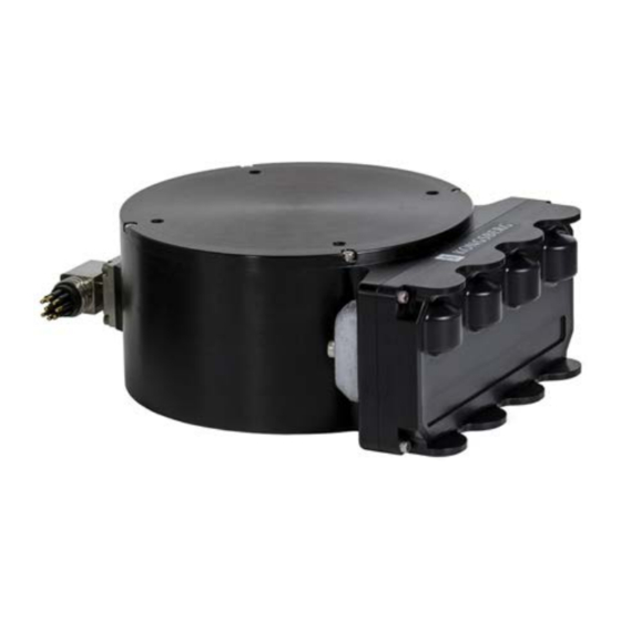
Page 15: Sonar Head
Prolonged exposure to ultra-violet rays and excessive heat may damage the surface of the polyurethane transducer face. Always store the Flexview in the provided equipment case when not in use. If the Flexview is mounted on an ROV, cover the transducer when not in use. -
Page 16: Getting Started
Flexview Reference Manual Getting started Topics Turning the Flexview on and off, page 15 Starting normal operation, page 17 922-20207001/1.0... -
Page 17: Turning The Flexview On And Off
Turning off the Flexview, page 16 Turning on the Flexview In order to use the Flexview, you must turn it on. You must first turn on the display and the Sonar Processor. After this you can start the Flexview software. -
Page 18: Turning Off The Flexview
The sonar will start pinging automatically once the connection is complete. Turning off the Flexview The Flexview is not provided with an on/off switch. Context When you do not use the Flexview, turn off the entire system. Procedure → If you are running the sonar, click in the Flexview software. -
Page 19: Starting Normal Operation
Flexview, and partly to set up the Flexview for normal use. If you already know the current operational settings are acceptable, you may not need to do any of these procedures. -
Page 20: Setting The Sonar Processor To High Performance
Flexview Reference Manual Setting the Sonar Processor to High Performance To avoid slowdowns or disruptions while running the sonar, ensure your Sonar Processor is using all of its processing power and does not go to sleep. Prerequisites ® This procedure is made for the Microsoft 64-bit Windows 10 operating system. -
Page 21: Installing The Flexview Software
Getting started Installing the Flexview software If your system is provided with a Sonar Processor, the Flexview software has already been installed. If you intend to use your own computer, you must install the software yourself. We recommended installing the latest Flexview software on your Sonar Processor. -
Page 22: Defining The Ip Address On The Sonar Processor Network Adapter
As long as you do not change the Sonar Processor to another computer, or replace the network adapter in your Sonar Processor, you will only need to do this once. Procedure On the Sonar Processor, close the Flexview software. Open the dialog box. -
Page 23: Changing The Frequency
Getting started Changing the frequency If you have a high-frequency Flexview transducer, you can change the frequency using Display Widget Context There are transducers with varying frequencies available for the Flexview. Note The frequency buttons will not appear if you are using a 500 kHz transducer. In addition, these buttons will not appear in playback mode. - Page 24 Flexview Reference Manual Procedure → Click to start the Sonar Head. Setup Connect Make sure that a sonar image appears in the sonar view window. Click the “i” icon in the top-left corner of the sonar view to open the...
-
Page 25: Testing The Sonar Head Telemetry
Prerequisites • For this test you will need the Sonar Head connected to the Sonar Processor and powered on. • The Flexview software must be running. ® • This procedure is made for the Microsoft 64-bit Windows 10 operating system. It is assumed that you are familiar with the Windows ®... - Page 26 The ping rate is normally taken from the sonar application or range setting. If the estimated available bandwidth is less than the bandwidth required by the sonar application/range, the Flexview software reduces the ping rate to compensate. Note The update rate is the number of times the sonar view is updated per second. The displayed ping rate may be different from the update rate because the system might be impacted by other processes.
- Page 27 If the Network utilization is less than 80%, disconnect the sonar, close all other programs, then reconnect the sonar. In general, make sure that your network environment supports the required link speed. In the Flexview software, look for any messages in the Output Messages window.
-
Page 28: Operating Procedures
Flexview Reference Manual Operating procedures Topics Setting up and running the sonar, page 27 Saving and recalling screen captures, page 38 Using sonar view overlays, page 46 Configuring the Sonar Head, page 52 922-20207001/1.0... -
Page 29: Setting Up And Running The Sonar
Operating procedures Setting up and running the sonar Topics Starting operation of the Sonar Head, page 28 Configuring your preferences, page 29 Choosing the sonar range, page 30 Adjusting the sonar view, page 31 Applying filters, page 34 Adjusting the TVG (Time Variable Gain) setting, page 34 Controlling the rotator, page 35 922-20207001/1.0... -
Page 30: Starting Operation Of The Sonar Head
Flexview Reference Manual Starting operation of the Sonar Head To start operation of the Flexview sonar, you may need to make sure that the Sonar Head has been discovered. Prerequisites • The Flexview software must be running. • The sound speed has been entered in →... -
Page 31: Configuring Your Preferences
Preferences Choose the unit of measurement for all the readouts related to range and distances in the Flexview user interface. Choose whether you would like to display the range and bearing or X and Y coordinates of your mouse cursor position. -
Page 32: Choosing The Sonar Range
Range horizontal distance covered by the Flexview. Context The Flexview Sonar Head can operate at different predefined near and far ranges. The range value is defined from the Sonar Head. Note You cannot change the range until the Sonar Head is connected. -
Page 33: Adjusting The Sonar View
The range is displayed with measured intervals in the sonar view. The current range will be updated when the Sonar Head is running. Adjusting the sonar view All echo information offered by the Flexview is shown in the sonar view. Context allows you to adjust the filter strength, change the display gain, and Display Widget choose your echo colours. - Page 34 Flexview Reference Manual Click the icon. Display Widget This icon is located in the lower-right corner of the sonar view. If you have a high-frequency transducer, click one of the buttons to select a frequency (in kHz). The frequency buttons will not appear if you are using a 500 kHz transducer.
- Page 35 Operating procedures Click to make the sonar view Full Screen full screen. Press the key to exit full-screen mode. Click to enable or disable the Annotations bearing and range annotations in the sonar view. Select to increase or decrease the Font Size size of the annotations in the sonar view.
-
Page 36: Applying Filters
Flexview Reference Manual Applying filters You can apply an averaging, background removal, or an edge enhancement filter to the sonar view. Context These buttons are located on the tool bar. Procedure Click one of the filter buttons. Observe the changes in the sonar view. -
Page 37: Controlling The Rotator
Apply Note The TVG profiles will not be saved when closing the software — default values will apply when starting up the Flexview software. Related topics TVG Setup dialog box, page 134 Controlling the rotator You can control your rotator(s) with the dialog box. - Page 38 Flexview Reference Manual Single-axis rotator with Pan/Tilt controls: Dual-axes rotator: Procedure → Click to start the Sonar Head. Setup Connect Observe that the dialog box opens. Rotator Control Click to enable the rotator controls or to disable the rotator Connect Disconnect controls.
- Page 39 Operating procedures If you have a Kongsberg 806-00360000 rotator, click the button. Calibrate If you are using Pan and Tilt controls, click the arrow buttons to move the Sonar Head. If you have a single-axis rotator, the arrow buttons will either pan or tilt, depending on the orientation of the rotator installation.
-
Page 40: Saving And Recalling Screen Captures
Flexview Reference Manual Saving and recalling screen captures Topics Saving and retrieving images, page 39 Recording sonar data, page 39 Playing back a recording, page 40 Converting your recordings, page 41 Saving GeoTiff files, page 43 922-20207001/1.0... -
Page 41: Saving And Retrieving Images
Operating procedures Saving and retrieving images With one click, you can capture an image of the sonar view — either with overlays or without overlays. Prerequisites Open the dialog box to change the default save location, choose your own Preferences filename, and add overlay text. -
Page 42: Playing Back A Recording
Open the dialog box to change the default save location, choose your own Preferences filename, and add overlay text. When the Flexview software isn’t running, double-click on a recording file to open the software and begin playback automatically. Procedure →... -
Page 43: Converting Your Recordings
.mmb files to .imb files using a batch conversion utility. Context The Flexview software records sonar data in two formats — raw element data (.mmb) or beamformed data (.imb). If you wish to convert a selected clip of data, you can play back an .mmb file and record the clip as an .imb file. - Page 44 Flexview Reference Manual Procedure Select Recording File to convert a single .mmb recording. Alternatively, select Recording Folder and Include Subdirectories to convert all your .mmb files. Click the button beside to select your .mmb file or folder. Browse Source Click the...
-
Page 45: Saving Geotiff Files
Prerequisites • You must have a position and heading sensor connected to your system and → sending data to the Flexview software. To add sensors, click Setup System → →... - Page 46 Flexview Reference Manual Context GeoTiff files contain georeferencing information and can be opened in third-party software, such as Google Earth Pro. Procedure → Click Setup Preferences Fill out the fields in the section. GeoTiff Auto Save To automatically save a GeoTiff file every set number of meters, select Distance and enter a value.
- Page 47 Operating procedures Alternatively, press to save a single GeoTiff file to your images folder. Your images will be saved under the folder “C:\KML\Flexview_V0100\Images” by default. You can change this save location through the dialog box. Preferences Related topics System Configuration dialog box - Sensors Setup page, page 96 System Configuration dialog box - Master Reference page, page 106 System Configuration dialog box - Mounting Offsets page, page 108 Geo Projection dialog box, page 84...
-
Page 48: Using Sonar View Overlays
Flexview Reference Manual Using sonar view overlays Topics Measuring distances, page 47 Measuring angles, page 48 Defining an area, page 48 Placing text labels, page 49 Placing reference cursors, page 50 Placing target markers, page 51 922-20207001/1.0... -
Page 49: Measuring Distances
Operating procedures Measuring distances You can use the tape measure tool to draw a line in the sonar view and measure the distance between two points. Context Measures distances on the sonar view. Also allows you to place a measurement overlay on the sonar view. -
Page 50: Measuring Angles
Flexview Reference Manual Measuring angles You can use the protractor to measure the angle between two lines, then place the resulting overlay in the sonar view. Context The protractor tool measures the angle between a baseline and a second line that intersects the baseline. -
Page 51: Placing Text Labels
Operating procedures Procedure Click the button. String Measure This button is located on the tool bar. Click anywhere in the sonar view to start a point. Move to the second point, then click again. Click as many times as necessary to create the required area. Double-click on the last point to finish. -
Page 52: Placing Reference Cursors
Flexview Reference Manual To remove this overlay, click the button, then click the overlay. Wiper Related topics Text Label, page 131 Placing reference cursors You can place one or two reference cursors as overlays on the sonar view. When you place two cursors, an additional overlay will appear with information about the cursors. -
Page 53: Placing Target Markers
Operating procedures Placing target markers The Target Marker function is primarily used for remotely operated vehicle (ROV) navigation. Third-party ROV software can use the time and location information to steer the ROV toward the target. Context You can press 0–9 to place a marker in the sonar view that is stamped with time and location information. -
Page 54: Configuring The Sonar Head
Flexview Reference Manual Configuring the Sonar Head Topics Upgrading the Sonar Head, page 53 Changing the Sonar Head IP Address, page 55 922-20207001/1.0... -
Page 55: Upgrading The Sonar Head
Operating procedures Upgrading the Sonar Head The Sonar Head has both software and firmware. You can upgrade these with the latest versions obtained from Kongsberg Mesotech. You can also use this same procedure to downgrade software and firmware versions. Prerequisites... - Page 56 Flexview Reference Manual Observe that a confirmation dialog box opens. Click to start the upgrade. If you click , the upgrade process will be aborted. The Sonar Cancel Stop Head software and firmware will not be changed. Select RX FPGA Configuration (receive firmware) under...
-
Page 57: Changing The Sonar Head Ip Address
Connect the Sonar Head directly to the computer network card. Do not connect through an intermediary device, such as a network switch or router. Power up the Sonar Head. Double click the Flexview icon on the desktop to run the Flexview software. → Click to start the Sonar Head. - Page 58 Flexview Reference Manual Enter the new IP Address in the table. Avoid setting the third octet of the IP Address to a value of 100 or more, as you may experience periodic drops in traffic. We recommend leaving the third octet set to the default value (1).
-
Page 59: User Interface
User interface User interface Topics Flexview presentation overview, page 58 The Flexview software menu system, page 60 Sonar view, page 61 Tool bar description, page 63 Status bar, page 65 922-20207001/1.0... -
Page 60: Flexview Presentation Overview
The presentation provides you with a lot of information. The sonar view presents sonar echo data. The menu system on the top gives you easy access to all the functionality offered by the Flexview software. The tool bar provides buttons for functions, filters, and sonar view overlays. The bottom... - Page 61 You can also repeat playback of the file on a never-ending loop. Status bar The status bar is located at the bottom of the Flexview presentation. It allows you to view the system status and disk space. You can also access detailed telemetry info. 922-20207001/1.0...
-
Page 62: The Flexview Software Menu System
The menu system is located on the top of the presentation. To open any of the menus, click the menu title. To select operational parameters on the Flexview, use the menu system. The menus are organized in a tree structure. Some of the menu items open dialog boxes to offer additional choices. -
Page 63: Sonar View
User interface Sonar view All echo information offered by the Flexview is shown in the sonar view. Description The range and bearing or X/Y coordinates of the current mouse cursor position is shown at the bottom of the sonar view. -
Page 64: Interpreting The Sonar View
Flexview Reference Manual You can change the physical size of the sonar view by clicking on the left view border, then dragging it to create a smaller or larger window. You can also make the sonar → view full screen by clicking... -
Page 65: Tool Bar Description
User interface Tool bar description The tool bar provides buttons for functions, filters, and sonar view overlays. The tool bar provides access to useful functions, such as the ability to take a screenshot or change your TVG settings. In addition, several measuring tools are available. Arrow Click to use the default arrow cursor. - Page 66 Flexview Reference Manual Image Quality Analysis System The Image Quality Analysis System (IQAS) analyzes the image quality of a point target, or can be used to measure a known point target against a specification. Horizontal line overlay that can be used to mark the depth of the natural seabed (for use when excavating).
-
Page 67: Status Bar
User interface Status bar The status bar is located at the bottom of the Flexview presentation. It allows you to view the system status and disk space. If network logging is enabled, you can view the sonar connection performance. You can also access detailed telemetry info. - Page 68 Flexview Reference Manual Offsets If Mounting Offsets Override is enabled then this text will appear during playback. Right-click on the status bar to configure it. You can show or hide any of the information displayed here. Related topics Recording sonar data, page 39...
-
Page 69: Menu System
Menu system Menu system Topics File menu, page 68 Display menu, page 69 Setup menu, page 71 Sonar Applications menu, page 72 Advanced menu, page 73 Help menu, page 74 922-20207001/1.0... -
Page 70: File Menu
Load User Settings Click to browse for a “UsersInfo.xml” file (in the folder C:\KML\Flexview_V0100\bin\SettingsFlexview) from a previous software version. You can import your previous settings to a new version of the Flexview software. • Exit Click to close the Flexview software. -
Page 71: Display Menu
Menu system Display menu Use the menu to control the visual aspects of the system, and to show or hide Display various elements in the presentation. How to open To open this menu, click the menu title. Description • Enable Target Marker Click to enable the Target Marker function. - Page 72 Flexview Reference Manual • Font Size You can choose between using a normal or a large font size throughout the Flexview software. • Palette Select to choose your preferred echo colours. Which colour scale to use is Palette mainly a personal preference based on ambient light conditions, the nature of the echoes and your own experience.
-
Page 73: Setup Menu
This dialog box allows you to System Configuration set up the Sonar Head, external sensors (such as a GPS or Motion Reference Unit), and rotators. In addition, you can configure the deployment of the Flexview and enter mounting offsets. 922-20207001/1.0... -
Page 74: Sonar Applications Menu
Flexview Reference Manual Sonar Applications menu menu lists various operating modes used for different Sonar Applications applications. Each mode has its own pre-defined characteristics, such as differing ranges, angular resolutions, and pulse types. Note You cannot select a sonar application until the Sonar Head is connected. All Sonar menu items will be greyed out until the sonar is running. -
Page 75: Advanced Menu
Advanced required for normal operation of the Flexview. This menu requires a software license key, and will not appear if you do not have one. How to open To open this menu, click the menu title. -
Page 76: Help Menu
Flexview Reference Manual Note To use this feature, you must run the Flexview software as an administrator (right-click on the icon and select Run as administrator Help menu menu allows you to view hardware and software information in the Help About dialog box. -
Page 77: Functions And Dialog Boxes
Functions and dialog boxes Functions and dialog boxes Topics File menu, page 76 Display menu, page 78 Setup menu, page 71 Sonar Applications menu, page 72 Advanced menu, page 73 Help menu, page 74 Tool bar description, page 63 922-20207001/1.0... -
Page 78: File Menu
Load User Settings Click to browse for a “UsersInfo.xml” file (in the folder C:\KML\Flexview_V0100\bin\SettingsFlexview) from a previous software version. You can import your previous settings to a new version of the Flexview software. • Exit Click to close the Flexview software. - Page 79 Therefore, data body size may change depending upon the mode. .imb files are easier to work with when using the Flexview MATLAB toolbox and can be used with third-party software, such as Echoview.
-
Page 80: Display Menu
Flexview Reference Manual Display menu Use the menu to control the visual aspects of the system, and to show or hide Display various elements in the presentation. How to open To open this menu, click the menu title. Description •... - Page 81 Functions and dialog boxes • Font Size You can choose between using a normal or a large font size throughout the Flexview software. • Palette Select to choose your preferred echo colours. Which colour scale to use is Palette mainly a personal preference based on ambient light conditions, the nature of the echoes and your own experience.
-
Page 82: Target Marker Export Dialog Box
Flexview Reference Manual Target Marker Export dialog box The Target Marker function is primarily used for remotely operated vehicle (ROV) navigation. Third-party ROV software can use the time and location information to steer the ROV toward the target. How to open This dialog box is opened from the menu. - Page 83 Functions and dialog boxes • Parity If required, a parity bit is used in a simple error detection algorithm for a serial port. • Stop Bits This parameter is used to indicate the end of the transmission. It is usually set to 1.
-
Page 84: Playback Console
Flexview Reference Manual Playback Console You can play back a previously recorded data file to view the sonar image sequence captured during operation of the Sonar Head. Control playback using the Playback Console How to open is opened from the menu. -
Page 85: Setup Menu
This dialog box allows you to System Configuration set up the Sonar Head, external sensors (such as a GPS or Motion Reference Unit), and rotators. In addition, you can configure the deployment of the Flexview and enter mounting offsets. Topics... -
Page 86: Geo Projection Dialog Box
Flexview Reference Manual Head Network Setup dialog box, page 89 Head Firmware Configuration dialog box, page 92 System Configuration dialog box - Sonar Setup page, page 93 System Configuration dialog box - Sensors Setup page, page 96 System Configuration dialog box - Rotators Setup page, page 99... - Page 87 Functions and dialog boxes Description This dialog box allows you to convert the latitude and longitude data from your GPS into a coordinate system of your choice. For example, you may wish to match the coordinate system used in your survey maps. You can display location data as Easting and Northing coordinates measured from a horizontal datum.
-
Page 88: Preferences Dialog Box
Flexview Reference Manual Details Datum • Latitude / Longitude Select a datum for latitude and longitude coordinates (geographic system). • Northing / Easting Select a datum for a Northing/Easting projection (projected coordinate system). • Zone Select a zone for a Northing/Easting projection. - Page 89 Functions and dialog boxes Description dialog box allows you to customize the software. In addition, you can Preferences configure features such as GeoTiff Auto Save and UDP Data Export. You can also configure unique filenames and save locations. 922-20207001/1.0...
- Page 90 Flexview Reference Manual Details Units • Meters Select to display all units of measurement in meters. • Feet Select to display all units of measurement in feet. Cursor Options • Range / Bearing Select to show the range and bearing of the current mouse position at the bottom of the sonar view.
-
Page 91: Head Network Setup Dialog Box
Functions and dialog boxes File Saving • Prompt User for Filename Check this box to open a “Save As” dialog box when you record data or save an image. • Name Type any name into the text box. The chosen name will be used as prefix in all the data file names. - Page 92 Flexview Reference Manual Note This dialog box is only available when the Sonar Head is connected and paused. To → pause the Sonar Head, click , then open the Menu Widget in the top-right Setup Connect corner of the sonar view. Click...
- Page 93 Functions and dialog boxes VDSL Profile The VDSL2 standard defines various profiles that can optimize the data rate and link performance on cables of different quality and lengths. For longer cables, you may wish to use a profile with a lower bandwidth, such as profile 0 (8b) or 1 (12a). The following profiles are available: •...
-
Page 94: Head Firmware Configuration Dialog Box
Flexview Reference Manual Related topics Changing the Sonar Head IP Address, page 55 Testing the Sonar Head telemetry, page 23 Head Firmware Configuration dialog box dialog box allows you to upgrade the Sonar Head Head Firmware Configuration firmware. How to open This dialog box is opened from the menu. -
Page 95: System Configuration Dialog Box - Sonar Setup Page
Functions and dialog boxes Description In addition to head application software, the Sonar Head has receive firmware (RX FPGA) and transmit firmware (TX FPGA). You can upgrade these by selecting the configuration type, browsing for the file, then clicking the button. - Page 96 Flexview Reference Manual Description This dialog box allows you to connect to the Sonar Head. You can connect manually or automatically each time you start the software. This dialog box also provides diagnostic network tools. 922-20207001/1.0...
- Page 97 Set the trigger mode to Master to send out a sync pulse so that the other acoustic device can be triggered. Set the trigger mode to Slave to be triggered by the sync pulse from the other device. For the Flexview, the default is set to Master.
-
Page 98: System Configuration Dialog Box - Sensors Setup Page
Flexview Reference Manual Override Network Link Speed If telemetry quality is poor, you can limit the network link speed. Be default, the network link speed is limited to 100 Mbps. There are no standard sonar applications with a telemetry-link speed requirement higher than 100 Mbps. - Page 99 Functions and dialog boxes Description If you have external sensors that provide speed, heading, or latitude/longitude coordinates, then this dialog box allows you to set them up. Readings from these sensors will appear in the located in the sonar view. Information Widget 922-20207001/1.0...
- Page 100 Flexview Reference Manual Details Add Device Click this button to add a sensor for data import. Remove Device Click this button to remove the selected sensor from the list. Sensor Devices Test Device Click this button to start a sensor test. The sensor data will be displayed in the box.
-
Page 101: System Configuration Dialog Box - Rotators Setup Page
System Configuration dialog box - Master Reference page, page 106 System Configuration dialog box - Rotators Setup page Rotators are required if you wish to pan or tilt the Flexview during operation. Use the page to set up and test your rotators. - Page 102 Flexview Reference Manual Description The Flexview software supports the following rotators. • Kongsberg OE 10-102: Dual-Axes Pan and Tilt unit • Kongsberg OE10-103: Single-Axis Pan unit • Kongsberg Mesotech 806-00360000 (SS350): Single-Axis high-precision Pan unit You must connect your rotator to a PC COM port.
- Page 103 Functions and dialog boxes Remove Device Click this button to remove the selected rotator from the list. Rotators Test Device Click this button to open the dialog box. Rotator Test Device Properties • Name Enter any name into this field to label the device. •...
- Page 104 Flexview Reference Manual • Interface This drop-down lists possible serial communication methods. Related topics System Configuration dialog box - Mounting Offsets page, page 108 Controlling the rotator, page 35 Rotator Test dialog box Test your rotators in this dialog box by making sure you can connect to the rotator and send commands to it.
- Page 105 Functions and dialog boxes If you have selected a single-axis rotator, then the following dialog box is used. Note This dialog box shows the options for the Kongsberg OE10-103. The Kongsberg Mesotech 806-00360000 (SS350) is similar, except a button appears. You must...
- Page 106 Click this button to disconnect from the rotator. Current Position Shows the current rotator position in degrees. button will appear here is you are using the Kongsberg Mesotech Calibrate 806-00360000 (SS350) rotator. Click this button to reset the zero index after powering down then powering up.
- Page 107 (pins) are usually bolted onto the rotator mount to stop rotation at predefined positions. However, soft stops allow you to program the rotator stops in the Flexview software to mitigate mechanical wear and avoid shearing the hard stops.
-
Page 108: System Configuration Dialog Box - Master Reference Page
Rotator Control Dialog Type Select Pan/Tilt Control if you wish to manually move the Sonar Head up, down, or sideways during operation. The 3D Scan option is not supported on the Flexview. System Configuration dialog box - Master Reference page... - Page 109 Functions and dialog boxes Description When using the Flexview for imaging, set up sensors for if you Position Heading want to create GeoTiff files or create a real-time mosaic. If no sensor input is required for a particular reference, you may leave the value set to Fixed.
-
Page 110: System Configuration Dialog Box - Mounting Offsets Page
Flexview Reference Manual • Depth The vertical distance downwards from the water surface. • Heading The direction in which a vessel is pointing, as opposed to the course made good. • Magnetic Variation If you are using a magnetic heading sensor, enter the local magnetic variation into the box to get true heading. - Page 111 This page is not available while the Sonar Head is running. Description When you mount your Flexview Sonar Head on an ROV, you will need to specify where the Sonar Head is positioned in three-dimensional space relative to the GPS antenna.
- Page 112 Observe the animation to make sure your Sonar Head is facing in the correct direction for the selected orientation. The orientation depends on how you are using the Flexview. For example, a forward-facing orientation can be used for obstacle avoidance on a remotely operated vehicle (ROV). If you wish to create your own orientation, select Custom, then enter in the precise pitch, roll, and yaw angles of the Sonar Head position.
- Page 113 Functions and dialog boxes • Angle Entering an angle is not necessary if the transducer face of the Sonar Head is aligned with the rotator. However, if the Sonar Head is installed at an angle to the rotator, then enter that value here. Override Mounting Parameters Enabling this option will apply the current offsets on this page during playback instead of the offsets recorded in your data file.
-
Page 114: Sonar Applications Menu
Flexview Reference Manual Sonar Applications menu menu lists various operating modes used for different Sonar Applications applications. Each mode has its own pre-defined characteristics, such as differing ranges, angular resolutions, and pulse types. Note You cannot select a sonar application until the Sonar Head is connected. All Sonar menu items will be greyed out until the sonar is running. -
Page 115: Enhanced Image Quality (Eiq)
Functions and dialog boxes • Rub Test Use this sonar application as part of a system test to make sure that the transducer is receiving a signal. Rub the transducer and make sure that bright streaks or rings appear in the sonar view. •... - Page 116 Flexview Reference Manual Details Sonar Application Names: Imaging Imaging Enhanced Range: 0.2 m to 150 m Angular Resolution: 1.6° x 30° Pulse Type: Continuous Wave and Linear FM (Chirp) 922-20207001/1.0...
-
Page 117: Advanced Menu
Advanced required for normal operation of the Flexview. This menu requires a software license key, and will not appear if you do not have one. How to open To open this menu, click the menu title. -
Page 118: Power User Settings Dialog Box
Flexview Reference Manual Power User Settings XML file, page 124 Power User Settings dialog box dialog box allows you to configure advanced controls. You can Power User Settings also override the beamlist or processing type during playback. The Ping Rate, Update Rate, and Mode ID are displayed for your information. - Page 119 Functions and dialog boxes • Range Processing This feature, when used together with Azimuth Processing, allows you to see the unprocessed raw data received directly from the transducer. If the transmit pulse is an LFM pulse, unchecking this box will not apply range compression to the raw data before the beamforming processing.
-
Page 120: Program Head Dialog Box - Production Config Page
Flexview Reference Manual • Mode ID All sonar applications have their own unique mode number. The mode number displayed here corresponds to a PRI Sequence ID found in the Flexview software database. Related topics Power User Settings XML file, page 124... - Page 121 Functions and dialog boxes Description Use the page to view or change advanced Sonar Head parameters, Production Config such as the Serial Number or MAC Address. This page is primarily intended for use by production test engineers. 922-20207001/1.0...
-
Page 122: Program Head Dialog Box - Head Corrections Page
Flexview Reference Manual Details Head table shows you the serial number and IP Address of the Sonar Head. Head Configuration file Click the folder icon to browse for the latest configuration file on your local drive. Click the button to populate the... - Page 123 Functions and dialog boxes Description Use the page to write Phase/Amplitude Corrections or Range Reference Head Corrections Coefficients to the Sonar Head. This page is primarily intended for use by production test engineers. Details Head table shows you the serial number and IP Address of the Sonar Head. Head Configuration type Select the type of configuration you wish to apply.
-
Page 124: Program Head Dialog Box - Tx Pulse Page
Use the page to apply a new TX pulse definition to the Sonar Head if a new TX Pulse TX pulse is designed for the Flexview software database. Details Configuration file Click the folder icon to browse for the latest configuration file on your local drive. -
Page 125: Raw Data Spectrum Window
Functions and dialog boxes Raw Data Spectrum window window allows you to find and observe any noise in the data. Raw Data Spectrum How to open This window is opened from the menu. Advanced Description This window displays the normalized, real-time raw data spectrum. The baseband sampling frequency range of the received signal is shown on the x-axis, and the normalized spectrum amplitude is shown on the y-axis (in dB). -
Page 126: Power User Settings Xml File
You need a software license key to apply the values in the “PowerUsersInfo.xml” XML file to the Flexview software. If you do not have a software license, then the default values will be used. The new values will be applied after restarting a licensed copy of the Flexview software. - Page 127 Note The other parameters in the Power User Settings XML file are for profiling applications only and are not supported by the Flexview. Related topics Power User Settings dialog box, page 116...
-
Page 128: Help Menu
Help menu menu allows you to view hardware and software information in the Help About dialog box. You can also open the Flexview Reference Manual from this menu. Flexview How to open To open this menu, click the menu title. -
Page 129: Tool Bar Description
Functions and dialog boxes Tool bar description The tool bar provides buttons for functions, filters, and sonar view overlays. The tool bar provides access to useful functions, such as the ability to take a screenshot or change your TVG settings. In addition, several measuring tools are available. Arrow Click to use the default arrow cursor. - Page 130 Flexview Reference Manual Image Quality Analysis System The Image Quality Analysis System (IQAS) analyzes the image quality of a point target, or can be used to measure a known point target against a specification. Horizontal line overlay that can be used to mark the depth of the natural seabed (for use when excavating).
-
Page 131: Arrow
Functions and dialog boxes Zoom windows, page 129 Tape Measure, page 130 Protractor, page 131 String Measure, page 131 Text Label, page 131 Reference cursors, page 132 Image Quality Analysis System, page 132 Save image with or without overlays, page 133 TVG Setup dialog box, page 134 Filters, page 137 Arrow... -
Page 132: Tape Measure
Flexview Reference Manual zoom windows (B) are acquired separately using high-resolution sampling parameters and adequate transmit pulses. If you record sonar data while the zoom windows are open, the zoom window data will also be recorded for replay. During playback, the zoom windows will open automatically. -
Page 133: Protractor
Functions and dialog boxes Related topics Measuring distances, page 47 Protractor You can use the protractor to measure the angle between two lines, then place the resulting overlay in the sonar view. The protractor tool measures the angle between a baseline and a second line that intersects the baseline. -
Page 134: Reference Cursors
Flexview Reference Manual If the text you entered does not fit within the text label overlay, you can resize the label by clicking on the label border, then dragging it to create a larger label. Related topics Placing text labels, page 49 Reference cursors You can place one or two reference cursors as overlays on the sonar view. -
Page 135: Save Image With Or Without Overlays
Functions and dialog boxes The following information will be displayed in the two IQAS dialog boxes. Resolution, Impulse Response Width (IRW) The IRW is measured 3 dB down from the top of the Main Lobe of the impulse response. In the range dialog box, the IRW is displayed in pixels and metres. In the azimuth angle dialog box, the IRW is displayed in pixels and degrees. -
Page 136: Tvg Setup Dialog Box
. The TVG profiles will not be saved when closing the Sonar applications list software — default values will apply when starting up the Flexview software. Click the button. This button is located on the tool bar. 922-20207001/1.0... - Page 137 That is why we normally refer to these factors as the two-way transmission loss. The TVG (Time Varible Gain) compensation is designed to counteract the natural phenomena of geometric spread and absorption loss. In the Flexview, the TVG compensation is made using digital signal processing software. By means of algorithms, the time variable gain compensation converts the echo presentation as a function of range.
- Page 138 Flexview Reference Manual that the signal is not being clipped. A slider is provided so that you can exclude the low end percent of the gain. Related topics Adjusting the TVG (Time Variable Gain) setting, page 34 922-20207001/1.0...
-
Page 139: Filters
Functions and dialog boxes Filters You can apply an averaging, background removal, or an edge enhancement filter to the sonar view. Note You can adjust the strength of these filters in the Display Widget Average Filter Clicking the “A” button will enable the Average Filter. This filter reduces noise. Slow-moving features persist on-screen. -
Page 140: Technical Specifications
Flexview Reference Manual Technical specifications Topics Introduction to technical specifications, page 139 Interface specifications, page 140 Performance specifications, page 143 Mechanical specifications, page 144 Power requirements, page 145 Environmental requirements, page 146 Minimum computer requirements, page 146 922-20207001/1.0... -
Page 141: Introduction To Technical Specifications
Technical specifications Introduction to technical specifications These technical specifications summarize the main functional and operational characteristics of the Flexview Multibeam sonar. It also provides information related to power requirements, physical properties and environmental conditions. Note At Kongsberg Mesotech, we are continuously working to improve the quality and performance of our products. -
Page 142: Interface Specifications
Flexview Reference Manual Interface specifications The Flexview Multibeam sonar will interface with peripheral systems and sensors using standard and/or proprietary datagram formats. Supported datagram formats for position information The Flexview supports the following datagram formats for position information. • NMEA GGA The NMEA GGA datagram transfers time-, position- and fix-related data from a global positioning system (GPS). - Page 143 Technical specifications • Kongsberg EM Attitude 3000 The EM Attitude 3000 is a proprietary datagram format created by Kongsberg for use with digital motion sensors. It holds roll, pitch, heave and heading information. The datagram contains a 10-byte message. •...
- Page 144 • Computer Time Sync If ZDA is configured, the Flexview software will use the time in the ZDA message to synchronize the computer clock automatically in the background. However, you may need to run the Flexview software as an administrator (right-click on the icon...
-
Page 145: Performance Specifications
Technical specifications Performance specifications These performance specifications summarize the main functional and operational characteristics of the Flexview system. • Range: – : 0.2 m to >150 m 500 kHz – : 0.2 m to 70 m 950 kHz - 1400 kHz •... -
Page 146: Mechanical Specifications
You can download these files from our website. • https://www.km.kongsberg.com/mesotechsoftware Mechanical specifications These mechanical specifications summarize the physical properties of the Flexview system. Sonar Processor The Sonar Processor uses a high-quality commercial-off-the-shelf laptop computer workstation. The weight and dimensions of the model may vary. Contact your Kongsberg Mesotech representative for information about the current model that is delivered with your Flexview system. -
Page 147: Power Requirements
• : SubConn Connector type • : 8 pin Connector model Power requirements These power characteristics summarize the supply power requirements for the Flexview system. Sonar Processor • : 120/240 VAC Power adapter input voltage • : 19.5 VDC @ 180W (max) -
Page 148: Environmental Requirements
(such as electric motors or welders). Minimum computer requirements Although a computer can be ordered from Kongsberg Mesotech as a part of the Flexview delivery, it is also possible to purchase one locally. If you purchase a computer locally, make sure that the chosen model meets the functional and technical requirements. - Page 149 10,000 or more (passmark.com). PassMark Software is a Windows computer performance benchmarking utility. Computers with a CPU score of 10,000 or higher have been tested with the Flexview. Lower-scoring computers may not perform well, resulting in a slow GUI response, slower ping rates, or dropped pings.
- Page 150 Flexview Reference Manual Index button Arrow............ 129 about Average Filter .......... 137 comments ..........7 Background Removal Filter ......137 constructive criticism........7 Edge Enhancement ........137 feedback............ 7 IQAS............. 132 purpose of this manual ........7 No Filter..........137 registered trademarks........
- Page 151 Index controlling Setup menu .......... 71, 83 rotator............35 Sonar Applications menu ....72, 112–113 converting sonar view ..........61 recordings ..........41 status bar ..........65 Cropped Width String measure ......... 131 Preferences dialog box ........89 system ............9 Current Position System Configuration dialog box.....
- Page 152 Flexview Reference Manual Preferences dialog box ........88 GeoTiff files echogram saving............43 choosing range ........... 30 Get Default Edge Enhancement Head Network Setup dialog box ....... 91 description ..........137 System Configuration dialog box...... 95 getting started purpose ..........72, 112 procedures ..........
- Page 153 IQAS File menu ..........68, 76 description ..........132 Help menu .......... 74, 126 Setup menu .......... 71, 83 Sonar Applications menu ......72, 112 Kongsberg Mesotech support ............ 13 icon Arrow............ 129 Average Filter .......... 137 Latitude / Longitude Background Removal Filter ......
- Page 154 Flexview Reference Manual Sonar Applications menu description ..72, Output Messages function 112–113 purpose ..........69, 78 menu system Overlay Text description ..........60 Preferences dialog box ........88 Meters Override Beamlist Preferences dialog box ........88 Power User Settings dialog box...... 117...
- Page 155 Index power supply playing back a record file ....... 40 introduction ..........12 recording sonar data ........39 overview ..........12 saving and retrieving images ......39 purpose ............ 12 saving GeoTiff files........43 Power User Settings dialog box testing the sonar and sensors ......23 Azimuth Processing ........
- Page 156 Flexview Reference Manual Power User Settings dialog box....73, 115 Reset to Default Layout function Preferences dialog box ......71, 83 purpose ..........70, 79 Program Head dialog box......73, 115 Roll Angle Raw Data Spectrum window ..... 73, 115 System Configuration dialog box....
- Page 157 Index Sonar Head system changing IP Address........55 description ..........9 introduction ..........13 diagram............ 10 overview ..........13 System Configuration dialog box purpose ............ 13 Add Device ......... 98, 100 testing ............. 21 Angle ............ 110 upgrading ..........53 Autoconnect at program start ......
- Page 158 Flexview Reference Manual Port ............80 Stop bits ........... 80 Unit Target Marker function System Configuration dialog box....101 description ..........80 Update Rate details............80 Power User Settings dialog box...... 117 target markers upgrading placing............. 51 Sonar Head ..........53...
- Page 160 ©2019 Kongsberg Mesotech...
Need help?
Do you have a question about the Flexview and is the answer not in the manual?
Questions and answers