Table of Contents
Advertisement
Quick Links
Advertisement
Table of Contents

Related Manuals for Kongsberg M3 Sonar HF


Summary of Contents for Kongsberg M3 Sonar HF
- Page 1 Reference Manual M3 Sonar® Multibeam sonar kongsberg.com/discovery 922-10017001...
- Page 3 Multibeam sonar Reference Manual Release 1.9 This manual provides you with reference information required to operate and fully understand the commands, menus, modes and options provided by the Kongsberg M3 Sonar Multibeam sonar. 922-10017001/1.9 April 2024 © Kongsberg Discovery Canada Limited...
- Page 4 Kongsberg Discovery disclaims any responsibility for damage or injury caused by improper installation, use or maintenance of the equipment. Disclaimer Kongsberg Discovery Canada Limited endeavours to ensure that all information in this document is correct and fairly stated, but does not accept liability for any errors or omissions. Support information If you require maintenance or repair, contact your local dealer.
-
Page 5: Table Of Contents
Reference Manual Table of contents ABOUT THIS MANUAL ..............7 M3 SONAR ................... 9 System description ........................ 10 System diagram........................11 System units .......................... 12 Sonar Processor ......................13 Power supply ....................... 13 Sonar Head ........................14 Support information ......................15 GETTING STARTED .............. - Page 6 M3 Sonar Controlling the rotator ....................49 Setting up dual M3 Sonars ..................54 Saving and recalling screen captures ..................65 Saving and retrieving images ..................66 Recording sonar data ....................66 Playing back a recording ..................... 68 Converting your recording format................69 Converting your recordings to video................
- Page 7 Reference Manual File menu ..........................115 Recording Format.......................116 Exporting Format .......................117 Convert to Video Format dialog box ................117 Display menu ........................123 Target Marker Export dialog box ................125 Playback Console ...................... 127 Profiling Settings dialog box ..................128 Setup menu ......................... 132 Define Custom Sensor dialog box ................
- Page 8 M3 Sonar Tape Measure......................196 Protractor ........................196 String Measure ......................196 Text Label........................197 Reference cursors ...................... 197 Image Quality Analysis System ................198 Save image with or without overlays ................ 199 TVG Setup dialog box....................200 Filters......................... 203 TECHNICAL SPECIFICATIONS..........
-
Page 9: About This Manual
Observe the registered trademarks that apply. Windows ® is a registered trademark of Microsoft Corporation in the United States and other countries. M3 Sonar ® is a registered trademark of Kongsberg Discovery Canada Limited in the United States and other countries. 922-10017001/1.9... - Page 10 We always want to improve our products. We also want our end-user documentation to be comprehensive and relevant. You can help. Please provide comments, suggestions or constructive criticism to our support office. You can contact us by phone at +1 604 464 8144, or by email at: support.vancouver@kd.kongsberg.com. 922-10017001/1.9...
-
Page 11: M3 Sonar
M3 Sonar M3 Sonar Topics System description, page 10 System diagram, page 11 System units, page 12 Support information, page 15 922-10017001/1.9... -
Page 12: System Description
M3 Sonar Reference Manual System description The Kongsberg Discovery M3 Sonar is a compact, versatile multibeam sonar. Multibeam sonars have an array of transducers that simultaneously transmits pings (sound pulses) at a specified frequency to cover a large area in less time than a single-beam transducer. -
Page 13: System Diagram
M3 Sonar System diagram The system diagram identifies the main components of a basic M3 Sonar system. Only the main connections between the units are shown. Detailed interface capabilities and power cables are not shown. Sonar Processor Power supply M3 Sonar Head 922-10017001/1.9... -
Page 14: System Units
M3 Sonar Reference Manual System units Topics Sonar Processor, page 13 Power supply, page 13 Sonar Head, page 14 922-10017001/1.9... -
Page 15: Sonar Processor
M3 Sonar Sonar Processor In this publication, the computer can also be referred to as the Processor Unit, and vice versa. The Sonar Processor contains the operational software, and offers the user interface that allows you to control the M3 Sonar. It is a vital part of the M3 Sonar system. The Sonar Processor runs the M3 software that manages communication with the Sonar Head, performs all beamforming and image processing and presents the sonar... -
Page 16: Sonar Head
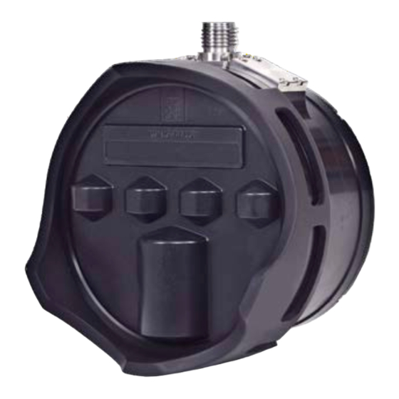
M3 Sonar Reference Manual Sonar Head When deployed underwater, the Sonar Head transmits and receives acoustic pulses. The Sonar Head includes transmit and receive transducers and the electronics to generate the transmit pulse and digitize the received signal. The sonar data is sent to the Sonar Processor using a standard Ethernet link. -
Page 17: Support Information
If you require maintenance or repair, contact your local dealer. You can contact us by phone at +1 604 464 8144, or by email at: support.vancouver@kd.kongsberg.com. If you need information about our other products, visit https://www.kongsberg.com/discovery/. On our website you will also find a list of our dealers and distributors. -
Page 18: Getting Started
M3 Sonar Reference Manual Getting started Topics Turning the M3 Sonar system on and off, page 17 Starting normal operation, page 19 922-10017001/1.9... -
Page 19: Turning The M3 Sonar System On And Off
Getting started Turning the M3 Sonar system on and off Topics Turning on the M3 Sonar system, page 17 Turning off the M3 Sonar system, page 18 Turning on the M3 Sonar system To use the M3 Sonar system, you must turn it on. You must first turn on the display and the computer. -
Page 20: Turning Off The M3 Sonar System
M3 Sonar Reference Manual Once the program has started, observe that the display presentation fills the entire screen. The software starts up using many of the same settings as the last time you used it. If these settings are acceptable, continue operation. If you wish to alter any of the settings, see the relevant procedures. -
Page 21: Starting Normal Operation
Getting started Starting normal operation Topics Introduction to the basic procedures, page 19 Setting the Sonar Processor to High Performance, page 20 Restoring USB Driver Functionality in Windows 10, page 21 Installing the M3 software, page 22 Defining the IP address on the computer's network adapter, page 23 Changing the frequency, page 24 Testing operation of the Sonar Head, page 24 Testing the Sonar Head telemetry, page 27... -
Page 22: Setting The Sonar Processor To High Performance
M3 Sonar Reference Manual Setting the Sonar Processor to High Performance To avoid slowdowns or disruptions while running the sonar, ensure your Sonar Processor is using all of its processing power and does not go to sleep. Prerequisites This procedure is made for the Microsoft ®... -
Page 23: Restoring Usb Driver Functionality In Windows 10
Getting started Restoring USB Driver Functionality in Windows 10 If you are using Windows 10, a new security feature may cause your system installation to fail, especially if you are using a USB port in your system. For example, a USB port is used to interface with a security key inserted into the USB port, or an Interface Unit connected via the USB port. -
Page 24: Installing The M3 Software
We recommended installing the latest M3 software on your Sonar Processor. Prerequisites • You can find the software on the Kongsberg USB drive included with the system, or you can contact your local dealer or distributor to have the latest software version installed. -
Page 25: Defining The Ip Address On The Computer's Network Adapter
Getting started Defining the IP address on the computer's network adapter The communication between the Sonar Processor and the Sonar Head is made using a high-speed Ethernet cable. If a Sonar Processor is not configured to connect to the sonar, you must define which IP Address and Subnet mask the Ethernet adapter in the Sonar Processor shall use for this communication. -
Page 26: Changing The Frequency
M3 Sonar Reference Manual Changing the frequency If you have a high-frequency M3 Sonar transducer, you can change the frequency using Display Widget Context Note The frequency buttons will not appear if you are using a 500 kHz transducer. In addition, these buttons will not appear in playback mode. - Page 27 Getting started Make sure there is sufficient disk space available to complete the survey. Procedure → Click to start the Sonar Head. Setup Connect Make sure that a sonar image appears in the sonar view window. 922-10017001/1.9...
- Page 28 M3 Sonar Reference Manual Click the “i” icon in the top-left corner of the sonar view to open the Information Widget Make sure that the sensor data is updating in the Information Widget Select Profiling from the menu. Sonar Apps Note The selection of sonar applications presented in menu depends on the current...
-
Page 29: Testing The Sonar Head Telemetry
Getting started Make sure there is no acoustic or electrical interference in the sonar view. Make sure that no concentric rings appear. These rings could be caused by other acoustic devices or power-line noise. Rings with black gaps between them could also be due to excess Ethernet traffic when using a shared network. - Page 30 M3 Sonar Reference Manual by selecting the appropriate sonar application and adjusting the Ethernet adapter settings to the corresponding link speed. Note There are no standard sonar applications with a telemetry-link speed requirement higher than 100 Mbps. The ping rate is normally taken from the sonar application or range setting. If the estimated available bandwidth is less than the bandwidth required by the sonar application/range, the M3 software reduces the ping rate to compensate.
- Page 31 Getting started Observe the graph to determine the average network link speed. An average link speed of at least 80 Mbps is required by most sonar applications (some applications and range scales will use less). A link speed of less than 80 Mbps may result in a slower than expected ping rate.
-
Page 32: Testing 1Pps Time Sync Mode
M3 Sonar Reference Manual Testing 1PPS Time Sync Mode If you have an M3 Sonar Head with a 1PPS connector, you can synchronize the Sonar Head clock with an external 1PPS source. After you have enabled the 1PPS Time Sync Mode, you can make sure it is working by reading through the log file. - Page 33 Getting started • INF SNSUDP IP Addr 192.168.1.233:13685, len=39 INF $GPZDA,171355.432,10,02,2018,00,00*5F The sensor data string received. The ZDA string will be displayed if valid, otherwise bytes of the received string will be displayed. • INF PPS preLD INF ZDA: 1518282835 2018/02/10/ 15:32:17.910 If valid ZDA data is being received, it will be displayed here in units of Epoch seconds GMT.
-
Page 34: Operating Procedures
M3 Sonar Reference Manual Operating procedures Topics Setting up and running the sonar, page 33 Saving and recalling screen captures, page 65 Using sonar view overlays, page 75 Configuring the Sonar Head, page 82 922-10017001/1.9... -
Page 35: Setting Up And Running The Sonar
Operating procedures Setting up and running the sonar Topics Starting operation of the Sonar Head, page 34 Configuring your preferences, page 35 Choosing the sonar range, page 36 Choosing a sonar application, page 37 Adjusting the sonar view, page 38 Applying filters, page 42 Adjusting the TVG (Time Variable Gain) setting, page 42 Setting up external sensors, page 43... -
Page 36: Starting Operation Of The Sonar Head
M3 Sonar Reference Manual Starting operation of the Sonar Head To start operation of the M3 Sonar sonar, you may need to make sure that the Sonar Head has been discovered. Prerequisites • The M3 software must be running. • The sound speed has been configured in →... -
Page 37: Configuring Your Preferences
Operating procedures Related topics Status bar, page 99 System Configuration dialog box - Sonar Setup page, page 146 Configuring your preferences You may wish to set up the system preferences to use measurement units appropriate to your location, or to choose a preferred save location for your recorded sonar data. Context dialog box is used to set up system preferences such as units of measure, Preferences... -
Page 38: Choosing The Sonar Range
M3 Sonar Reference Manual Choosing the sonar range function allows you to specify the maximum theoretical vertical depth and Range horizontal distance covered by the M3 Sonar. Context The M3 Sonar Sonar Head can operate at different predefined near and far ranges. -
Page 39: Choosing A Sonar Application
Operating procedures You can increase or decrease the range using the range slider bar to the left of the sonar view. Click the top arrows to increase or decrease the far range. Note To change the depth range settings in the window, click , uncheck 3D Point Cloud... -
Page 40: Adjusting The Sonar View
M3 Sonar Reference Manual Each sonar application has its own TVG profile. Before changing the TVG settings, select the sonar application you want to configure from the . Click the Sonar applications list button. This button is located on the tool bar. Procedure →... - Page 41 Operating procedures Note If you have a high-frequency M3 Sonar transducer, you can change the frequency using Display Widget menu allows you to configure a number of options in the sonar view, including Display making the sonar view full screen and adjusting the annotations, palette, or sector orientation.
- Page 42 M3 Sonar Reference Manual To adjust the display gain manually, check the box and drag the slider to Gain increase or decrease the gain. controls the "amount" of echo that is displayed, in other words the Display Gain "strength" or "intensity" of the echo presentation. Uncheck the box if you want the software to adjust the gain automatically.
- Page 43 Operating procedures Use the menu to control the visual aspects of the system, and to show or hide Display various elements in the presentation. Click to make the sonar view full Full Screen screen. Press the key to exit full-screen mode. Click to enable or disable the Annotations...
-
Page 44: Applying Filters
M3 Sonar Reference Manual Applying filters You can apply an averaging, background removal, or an edge enhancement filter to the sonar view. Context These buttons are located on the tool bar. Procedure Click one of the filter buttons. Observe the changes in the sonar view. Increase or decrease the filter effect. -
Page 45: Setting Up External Sensors
Operating procedures Click the button. This button is located on the tool bar. Drag the sliders to adjust the A, B, C, and L Factors. Click the arrow buttons to make small adjustments. Click to save the settings. Apply Note If you are using a high-frequency M3 Sonar, the TVG profiles will not be saved when closing the software —... - Page 46 M3 Sonar Reference Manual Procedure On the Sonar Processor desktop, double-click the M3 Sonar icon to start the software. → Click Setup System → → Configuration Devices Sensors Setup Configure your external sensors in the dialog box. Click Add Device Select the type of sensor you are using from the drop-down...
- Page 47 Operating procedures Click when done. Stop Test Make your external sensors a Master Reference. → Select the Deployment Master tab. Reference On the page, you Master Reference can assign any external sensors you have set up as the primary source for various types of navigational data.
-
Page 48: Defining A Custom Sensor
M3 Sonar Reference Manual Select the correct from the drop-down list. Orientation Match the orientation to the physical installation of your Sonar Head. For example, if the transducer face is pointing down towards the sea bottom for a bathymetry application, select Downward. Defining a custom sensor You will find many supported sensor formats in the drop-down list found on... - Page 49 Operating procedures Enter in the Message ID. The start (prefix) of the sensor sentence. Refer to the manufacturer's sensor specification to determine what to use. For example, “:” or “$GPRMC”. Select one or more delimiters. The character used to separate each string in the sentence. You can select more than one if necessary - each character will be treated as one delimiter.
- Page 50 M3 Sonar Reference Manual Enter the Message ID, followed by the chosen delimiter. Enter in one or more of the three-letter definition strings from the list on the right side of the dialog box. Match each three-letter string with the data type in the sensor specification. For example, enter "ALT"...
-
Page 51: Controlling The Rotator
Operating procedures Select to continue. Next Enter in a unique name for your custom sensor. This name will appear in the drop-down list found on the page Protocol Sensors Setup in the dialog box. System Configuration 10 Select to close the wizard. Finish 11 Set up the custom sensor in the software to start using it. - Page 52 M3 Sonar Reference Manual • If you have a single-axis rotator, choose the type of control you would like in the Rotator dialog box. On the page, select your single-axis rotator in the Test Rotators Setup Rotators table, click the button, then select either 3D Scan or Pan/Tilt Control from the Test Device drop-down list.
- Page 53 Operating procedures Single-axis rotator with 3D Scan controls: 922-10017001/1.9...
- Page 54 Connect Disconnect If you have a Kongsberg 806-00480000 rotator, click the button. Calibrate If you are using Pan and Tilt controls, click the arrow buttons to move the Sonar Head.
- Page 55 Operating procedures Drag the slider to define the centre of the scan coverage. Center Drag the slider to set the rotator speed. Slower speeds will result in higher Speed angular resolutions. Check the box to record data during the scan. Record Click Start Scan...
-
Page 56: Setting Up Dual M3 Sonars
M3 Sonar Reference Manual Setting up dual M3 Sonars You can run two sonars simultaneously, either on the same computer or on separate computers. The two sonars must be synchronized so that they do not interfere with each other. Context When running two M3 Sonars simultaneously, they must be connected to each other with a sync cable (Part Number 436-02810000). - Page 57 Operating procedures Dual M3 Sonar Setup using the ROV survey MUX and exporting data to the EIVA NaviSuite computer 922-10017001/1.9...
- Page 58 M3 Sonar Reference Manual Procedure Install the M3 Sonar software. If you are running two sonars on separate computers, perform a normal installation of the M3 software on each computer. Select the Standard Installation option when going through the software installation wizard.
- Page 59 Operating procedures If you are running two sonars on the same computer, run the software installation wizard and select the Dual-M3 on Same PC option. The installation wizard will create two icons on the computer desktop: M3 2.5.4 Master and M3 2.5.4 Slave. Note Each sonar will be running on its own instance of software with separate settings, even when selecting the dual M3 Sonar option.
- Page 60 M3 Sonar Reference Manual Double click M3 2.5.4 Master to run the software for the “Master” sonar. If you are running two sonars on separate computers, run the M3 software on the computer where you wish to run the “Master” sonar. →...
- Page 61 → → Select File Exporting Format Profile Point (.all) The default “.all” format is the Kongsberg EM datagram standard and can be processed by third-party software. → Click Setup Preferences In the UDP Data Export section, enter the “Master” UDP port into the Port field.
- Page 62 → → Select File Exporting Format Profile Point (.all) The default “.all” format is the Kongsberg EM datagram standard and can be processed by third-party software. → Click Setup Preferences In the UDP Data Export section, enter the “Slave” UDP port into the Port field.
- Page 63 Operating procedures Important The “Master” UDP port must be different from the “Slave” UDP port. For example, set the “Master” UDP port to 20002 and the “Slave” UDP port to 20003. Enter the IP Address of the computer running the third-party software into field.
- Page 64 M3 Sonar Reference Manual In the section of the dialog box, select Image and Display Mode Profiling Settings Profile or Profile Only to display profile points in the window. 3D Point Cloud → If the profiling settings are not visible, click to open the Display Profiling Settings...
- Page 65 Operating procedures Note When power is disconnected to the sonars, a “Failed to connect to 192.168.1.xxx:30” message will appear. The software will continue attempting to reconnect until the sonar is powered back on or the cables have been reconnected. Start operation of “Slave” sonar. Double click M3 2.5.4 Slave to run the software for the “Slave”...
- Page 66 M3 Sonar Reference Manual → If the profiling settings are not visible, click to open the Display Profiling Settings dialog box. Profiling Settings For the best profiling results, select Split Beam from the drop-down list Algorithm and select Strongest from the drop-down list.
-
Page 67: Saving And Recalling Screen Captures
Operating procedures Saving and recalling screen captures Topics Saving and retrieving images, page 66 Recording sonar data, page 66 Playing back a recording, page 68 Converting your recording format, page 69 Converting your recordings to video, page 70 Saving GeoTiff files, page 72 922-10017001/1.9... -
Page 68: Saving And Retrieving Images
M3 Sonar Reference Manual Saving and retrieving images With one click, you can capture an image of the sonar view — either with overlays or without overlays. Prerequisites Open the dialog box to change the default save location, choose your own Preferences filename, and add overlay text. - Page 69 Operating procedures Context Running the sonar and recording simultaneously (real-time recording) requires significant processing power, especially if trying to save beamformed data (an “.imb” file). For real-time recording, we recommend using the “.mmb” recording format. If you prefer an “.imb” file, we recommend either using the dialog Convert to Video Format box to convert the file from “.mmb”...
-
Page 70: Playing Back A Recording
M3 Sonar Reference Manual Playing back a recording You can play back a previously recorded data file to view the sonar image sequence captured during operation of the Sonar Head. Prerequisites Open the dialog box to change the default save location, choose your own Preferences filename, and add overlay text. -
Page 71: Converting Your Recording Format
Operating procedures Converting your recording format If you want to keep your recordings in .mmb format but process your data in .imb format, you can convert .mmb files to .imb files using a batch conversion utility. Context The M3 software records sonar data in two formats — raw element data (.mmb) or beamformed data (.imb). -
Page 72: Converting Your Recordings To Video
M3 Sonar Reference Manual Procedure Select Recording File to convert a single .mmb recording. Alternatively, select Recording Folder and Include Subdirectories to convert all your .mmb files. Click the button beside to select your .mmb file or folder. Browse Source Click the button beside to select where you want to save the... - Page 73 Operating procedures Procedure → Click File Convert To Video Observe that the dialog box opens. Convert To Video Format Select the desired video conversion settings. 922-10017001/1.9...
-
Page 74: Saving Geotiff Files
M3 Sonar Reference Manual To convert a single data file, select the button and use the browser window Source File to select the file. To batch convert all sonar recordings in a selected folder, select the Folder Conversion checkbox, then select the button to select the folder in the browser Source Folder window. - Page 75 Operating procedures Context GeoTiff files contain georeferencing information and can be opened in third-party software, such as Google Earth Pro. Procedure → Click Setup Preferences Fill out the fields in the section. GeoTiff Auto Save To automatically save a GeoTiff file every set number of meters, select Distance and enter a value.
- Page 76 M3 Sonar Reference Manual Press F11 to enable or disable GeoTiff auto save. The status bar will display “GeoTiff” in green when auto save is enabled. When GeoTiff autosave is enabled, GeoTiff files will be saved automatically and continuously based on travel distance or time. Alternatively, press to save a single GeoTiff file to your images folder.
-
Page 77: Using Sonar View Overlays
Operating procedures Using sonar view overlays Topics Measuring distances, page 76 Measuring angles, page 77 Defining an area, page 78 Placing text labels, page 78 Placing reference cursors, page 79 Placing target markers, page 80 922-10017001/1.9... -
Page 78: Measuring Distances
M3 Sonar Reference Manual Measuring distances You can use the tape measure tool to draw a line in the sonar view and measure the distance between two points. Context Measures distances on the sonar view. Also allows you to place a measurement overlay on the sonar view. -
Page 79: Measuring Angles
Operating procedures Measuring angles You can use the protractor to measure the angle between two lines, then place the resulting overlay in the sonar view. Context The protractor tool measures the angle between a baseline and a second line that intersects the baseline. -
Page 80: Defining An Area
M3 Sonar Reference Manual Defining an area You can use the string measure tool to define an area. The size and perimeter of the area will be calculated for you. Context Defines and measures perimeters and areas. Allows you to place an area overlay on the sonar view. -
Page 81: Placing Reference Cursors
Operating procedures Procedure Click the button. Text Label This button is located on the tool bar. In the sonar view, click the area of interest that you want to label. Click and hold the left mouse button on the label overlay and drag it to a place on the screen where the text is legible. -
Page 82: Placing Target Markers
M3 Sonar Reference Manual Move the mouse to where you want to place the cursor. To make fine adjustments to the cursor position, drop a reference cursor into a Zoom window. Click the left mouse button to place the cursor as an overlay in the sonar view. The range and bearing of the cursor’s position —... - Page 83 Operating procedures Choose a serial port from the drop-down list. Note The default serial settings cannot be altered. Click to enable serial port export. Alternatively, click to use the Target Marker function without exporting to Cancel a serial port. UDP export is always available, whether you enable serial port export or not. Move the mouse cursor to the location in the sonar view where you wish to place a marker.
-
Page 84: Configuring The Sonar Head
M3 Sonar Reference Manual Configuring the Sonar Head Topics Upgrading the Sonar Head, page 83 Changing the Sonar Head IP Address, page 85 922-10017001/1.9... -
Page 85: Upgrading The Sonar Head
Operating procedures Upgrading the Sonar Head The Sonar Head has both software and firmware. You can upgrade these with the latest versions obtained from Kongsberg Discovery. You can also use this same procedure to downgrade software and firmware versions. Prerequisites... - Page 86 M3 Sonar Reference Manual Click the file folder icon under to browse and select the .ASW Configuration file file on your local drive. Use the .ASW file with the same version as the .RXF file. Click Write Observe that a confirmation dialog box opens. Click to start the upgrade.
-
Page 87: Changing The Sonar Head Ip Address
Operating procedures → Click Setup Head Firmware Configuration Observe that the dialog box opens. Head Firmware Configuration Confirm that the software and firmware has been upgraded from the versions you took note of earlier. Note The receive hardware (RX HW) and software (RX SW) must both be on the same version. - Page 88 M3 Sonar Reference Manual Click the circular icon in the top-right corner of the sonar view to open the Menu Widget Click Pause Write the new IP Address to the Sonar Head. → Click Setup Head Network Setup Observe that the dialog box opens.
- Page 89 Operating procedures Related topics Defining the IP address on the computer's network adapter, page 23 Head Network Setup dialog box, page 142 922-10017001/1.9...
-
Page 90: User Interface
M3 Sonar Reference Manual User interface Topics Presentation overview, page 89 The M3 software menu system, page 91 Sonar view, page 92 3D Point Cloud, page 95 Tool bar description, page 97 Status bar, page 99 922-10017001/1.9... -
Page 91: Presentation Overview
User interface Presentation overview By default, the display presentation covers the entire screen. This M3 Sonar screen capture shows you a typical data replay situation. The presentation provides you with a lot of information. The sonar view presents sonar echo data. - Page 92 M3 Sonar Reference Manual Range slider bar When the sonar is running, you can increase or decrease the range using the range slider bar to the left of the sonar view. Click the top arrows to increase or decrease the far range. Profiling Settings In the dialog box, you can choose to display only the sonar view, only...
-
Page 93: The M3 Software Menu System
User interface The M3 software menu system The menu system is located on the top of the presentation. To open any of the menus, click the menu title. To select operational parameters on the M3 Sonar, use the menu system. The menus are organized in a tree structure. -
Page 94: Sonar View
M3 Sonar Reference Manual Sonar view All echo information offered by the M3 Sonar is shown in the sonar view. Description 922-10017001/1.9... -
Page 95: Interpreting The Sonar View
User interface The range and bearing or X/Y coordinates of the current mouse cursor position is shown at the bottom of the sonar view. Click the icon in the top-left corner of the sonar view to open the . The Information Widget Information Widget displays sonar pulse details as well as vessel speed, sound... -
Page 96: Noise And Interference
M3 Sonar Reference Manual will not generate any echoes. This is very similar to the shadow formed when an object is illuminated with a single light source. The shadow behind a target can often yield more information about the target than the reflections from the target itself. The shadow will often reveal the shape of the target, but you must remember that the shape will usually be distorted according to the position of the Sonar Head relative to the target and the bottom, and according to the slope of the bottom. -
Page 97: Point Cloud
User interface 3D Point Cloud The 3D Point Cloud presents profile point data that can be rotated in three dimensions. Description Profiling mode allows you to view a real-time 3D point cloud of the sea bottom or structures under the water. The profile point data can be exported to a file so that third-party software can extract depth, distance, and volume measurements. - Page 98 M3 Sonar Reference Manual To change the depth range settings in the window, click , uncheck the 3D Point Cloud Depth box, enter the top and bottom depth, then click . To change the colour Adaptive Palette Apply scale of the 3D Point Cloud, click , check the box, then click Depth...
-
Page 99: Tool Bar Description
User interface Tool bar description The tool bar provides buttons for functions, filters, and sonar view overlays. The tool bar provides access to useful functions, such as the ability to take a screenshot or change your TVG settings. In addition, several measuring tools are available. Arrow Click to use the default arrow cursor. - Page 100 M3 Sonar Reference Manual Image Quality Analysis System The Image Quality Analysis System (IQAS) analyzes the image quality of a point target, or can be used to measure a known point target against a specification. Horizontal line overlay that can be used to mark the depth of the natural seabed (for use when excavating).
-
Page 101: Status Bar
User interface Status bar The status bar is located at the bottom of the M3 Sonar presentation. It allows you to view the system status and disk space. If network logging is enabled, you can view the sonar connection performance. You can also access detailed telemetry info. Recording information Displays the filename when you are recording data. - Page 102 M3 Sonar Reference Manual System status Shows the system status, such as “Active” when the system is connected to a Sonar Head, “Inactive” when not connected, or “Playback” when replaying a recorded file. Clicking the system status text will open a window.
-
Page 103: Menu System
Menu system Menu system Topics File menu, page 102 Display menu, page 103 Setup menu, page 106 Sonar Applications menu, page 108 Advanced menu, page 112 Help menu, page 113 922-10017001/1.9... -
Page 104: File Menu
• Exporting Format You can choose the exporting format for sonar data. The default “.all” format is the Kongsberg EM datagram standard and can be processed by third-party software. • Load User Settings Click to browse for a “UsersInfo.xml” file (in the folder C:\KML\M3_V0254\bin\Settings) from a previous software version. -
Page 105: Display Menu
Menu system Display menu Use the menu to control the visual aspects of the system, and to show or hide various Display elements in the presentation. How to open To open this menu, click the menu title. Description • Enable Target Marker Click to enable the Target Marker function. - Page 106 M3 Sonar Reference Manual Click to show or hide the dialog box for each rotator you have installed. Rotator Control • Tool bar Click to show or hide the tool bar. The tool bar provides buttons for functions, filters, and sonar view overlays. •...
- Page 107 Menu system Click to reset the presentation layout. All windows and dialog boxes will be docked in their default location. In addition, some display elements are hidden by default. 922-10017001/1.9...
-
Page 108: Setup Menu
M3 Sonar Reference Manual Setup menu You can connect to the Sonar Head using the menu. You can also configure the Setup system, choose your preferences, set up the coordinate system, upgrade the Sonar Head firmware, or change the Sonar Head IP Address. How to open To open this menu, click the menu title. - Page 109 Menu system Click to open the dialog box. This dialog box allows you to set up System Configuration the Sonar Head, external sensors (such as a GPS or Motion Reference Unit), and rotators. In addition, you can configure the deployment of the M3 Sonar and enter mounting offsets.
-
Page 110: Sonar Applications Menu
M3 Sonar Reference Manual Sonar Applications menu menu lists various operating modes used for different applications. Sonar Applications Each mode has its own pre-defined characteristics, such as differing ranges, angular resolutions, and pulse types. Note You cannot select a sonar application until the Sonar Head is connected. All Sonar menu items will be greyed out until the sonar is running. - Page 111 Menu system The following sonar applications are available when using a 500-kHz Sonar Head transducer. Description • This sonar application captures high-quality images. At short ranges the images are relatively insensitive to the motion of the sonar. At longer ranges the sonar should be relatively motionless.
- Page 112 M3 Sonar Reference Manual Use this sonar application primarily for profiling using a 3-degree Tx vertical beamwidth. You may also use this application for shallow-water obstacle avoidance. • Imaging 30 You can use this sonar application for navigation and obstacle avoidance. This application uses a 30-degree Tx vertical beamwidth.
- Page 113 Menu system good image update rate at short ranges. EIQ is used for medium ranges. Imaging 30 is used for long ranges. • Rub Test Use this sonar application as part of a system test to make sure that the transducer is receiving a signal.
-
Page 114: Advanced Menu
M3 Sonar Reference Manual Advanced menu menu is intended for experienced users or for testing purposes and is not Advanced required for normal operation of the M3 Sonar. This menu requires a software license key, and will not appear if you do not have one. How to open To open this menu, click the menu title. -
Page 115: Help Menu
Menu system Help menu menu allows you to view hardware and software information in the Help About M3 dialog box. You can also open the M3 Sonar Reference Manual from this menu. How to open To open this menu, click the menu title. Description About M3 dialog box identifies the current software version. -
Page 116: Functions And Dialog Boxes
M3 Sonar Reference Manual Functions and dialog boxes Topics File menu, page 115 Display menu, page 103 Setup menu, page 106 Sonar Applications menu, page 108 Advanced menu, page 112 Help menu, page 113 Tool bar description, page 97 922-10017001/1.9... -
Page 117: File Menu
• Exporting Format You can choose the exporting format for sonar data. The default “.all” format is the Kongsberg EM datagram standard and can be processed by third-party software. • Load User Settings Click to browse for a “UsersInfo.xml” file (in the folder C:\KML\M3_V0254\bin\Settings) from a previous software version. -
Page 118: Recording Format
M3 Sonar Reference Manual Convert to Video Format dialog box, page 117 Recording Format Click Recording Format to choose between recording raw sonar data (to a “.mmb” file) or recording beamformed sonar data (to a “.imb” file). The following processed data output formats are available. .mmb .mmb is the default recommended recording format. -
Page 119: Exporting Format
This is an ASCII point cloud format for M3 rotator 3D profiling data on a tripod only. .all (recommended default) This M3 profiling data format uses the Kongsberg EM datagram standard. The “.all” file can be processed by third-party software such as Hypack, QINSy, Caris, and EIVA. - Page 120 M3 Sonar Reference Manual Description Use this dialog box if you want to export a recording to a format that is playable by any media player. This function is useful if you wish to share recordings with others who do not have the M3 software installed on their computers, or if you wish to upload your recording to an online service.
- Page 121 Functions and dialog boxes Details Frame Rate • Match Ping Rate Select if you want the converted video frame time to match the ping time. • One Frame per Ping Select if you want each video frame to be converted from each sonar ping. Gain Control •...
- Page 122 M3 Sonar Reference Manual Date/Time You can choose whether to display Coordinated Universal Time (UTC) Time or Local Time in the in the sonar view. Information Widget Note During the winter, Local Time equals standard time. During the summer, Local Time equals Daylight Saving Time (DST).
- Page 123 Functions and dialog boxes Folder Conversion Select this checkbox to perform a batch conversion of all sonar recordings in a selected folder. If you select this option, you will not be able to change the name of the converted files. Auto Name will be selected under the Target file naming convention drop-down list and the other options will not be available.
- Page 124 M3 Sonar Reference Manual Related topics Playing back a recording, page 68 Converting your recordings to video, page 70 922-10017001/1.9...
-
Page 125: Display Menu
Functions and dialog boxes Display menu Use the menu to control the visual aspects of the system, and to show or hide various Display elements in the presentation. How to open To open this menu, click the menu title. Description •... - Page 126 M3 Sonar Reference Manual Click to show or hide the dialog box for each rotator you have installed. Rotator Control • Tool bar Click to show or hide the tool bar. The tool bar provides buttons for functions, filters, and sonar view overlays. •...
-
Page 127: Target Marker Export Dialog Box
Functions and dialog boxes Click to reset the presentation layout. All windows and dialog boxes will be docked in their default location. In addition, some display elements are hidden by default. Topics Target Marker Export dialog box, page 125 Playback Console, page 127 Profiling Settings dialog box, page 128 Target Marker Export dialog box The Target Marker function is primarily used for remotely operated vehicle (ROV) - Page 128 M3 Sonar Reference Manual Serial port parameters The serial port parameters are fixed and cannot be changed. Ensure that your third-party software is set to receive the data using these values. • Baud Rate 9600 The speed of the serial communication. •...
-
Page 129: Playback Console
Functions and dialog boxes ‘f’: Northing/Easting in feet. Variable number of digits for Northing/Easting and variable number of digits for decimal-fraction of Northing/Easting. ‘m’: Northing/Easting in metres. Variable number of digits for Northing/Easting and variable number of digits for decimal-fraction of Northing/Easting. ‘l’: Lat/Lon in degrees. -
Page 130: Profiling Settings Dialog Box
M3 Sonar Reference Manual The playback progress bar. Click and hold, then drag your mouse along the bar to search through the recording. Click anywhere in the bar to jump to a specific point. Click to stop the recording. Click to pause the recording. Click to fast forward through the recording. - Page 131 Functions and dialog boxes Description In the dialog box, you can choose to display only the sonar view, only the Profiling Settings 3D Point Cloud, or both. The profile point data can be exported to a file so that third-party software can extract depth, distance, and volume measurements.
- Page 132 M3 Sonar Reference Manual Point Size Select the size of the displayed profile points. Algorithm Select the profiling algorithm. The default setting is optimal for most conditions. The Split Beam algorithm will improve point detection with sub-degree accuracy at a low grazing angle (but with the compromise of a lower ping rate).
- Page 133 Functions and dialog boxes • Min Sector Drag the slider to set the lower angle limit of the profile points. No profile points will be detected below this angle. Depth Tracking Check this box to automatically adjust the range according to the current depth when the head is running.
-
Page 134: Setup Menu
M3 Sonar Reference Manual Setup menu You can connect to the Sonar Head using the menu. You can also configure the Setup system, choose your preferences, set up the coordinate system, upgrade the Sonar Head firmware, or change the Sonar Head IP Address. How to open To open this menu, click the menu title. -
Page 135: Define Custom Sensor Dialog Box
Functions and dialog boxes Click to open the dialog box. This dialog box allows you to set up System Configuration the Sonar Head, external sensors (such as a GPS or Motion Reference Unit), and rotators. In addition, you can configure the deployment of the M3 Sonar and enter mounting offsets. - Page 136 M3 Sonar Reference Manual Description Many third-party sensors or ROV systems export sensor strings through a UDP or serial connection. These sensor strings include various data types such as position, heading, depth, pressure, altitude, pitch, roll, and water temperature. The third-party sensor string may not conform to the universal NMEA standard and will change depending on the sensor or ROV manufacturer.
- Page 137 Functions and dialog boxes The sensor string is comprised of a sentence with defined parts: Message ID + Sensor Format and Delimiters + Termination. Details Message ID The start (prefix) of the sensor sentence. Refer to the manufacturer's sensor specification to determine what to use. For example, “:” or “$GPRMC”. Delimiter(s) The character used to separate each string in the sentence.
-
Page 138: Geo Projection Dialog Box
M3 Sonar Reference Manual Unit Scale Factor The dialog box will tell you what unit scale the software expects (meters, degrees, meters per second, and so on). If the data type in the specification does not match the required unit scale, you must enter an appropriate scaling factor. For example, if the Depth data type is in feet, then you must enter 0.3048 to scale the depth value to meters. - Page 139 Functions and dialog boxes Description This dialog box allows you to convert the latitude and longitude data from your GPS into a coordinate system of your choice. For example, you may wish to match the coordinate system used in your survey maps. You can display location data as Easting and Northing coordinates measured from a horizontal datum.
-
Page 140: Preferences Dialog
M3 Sonar Reference Manual Details Datum • Latitude / Longitude Select a datum for latitude and longitude coordinates (geographic system). • Northing / Easting Select a datum for a Northing/Easting projection (projected coordinate system). • Zone Select a zone for a Northing/Easting projection. •... - Page 141 Functions and dialog boxes Description dialog box allows you to customize the software. In addition, you can Preferences configure features such as GeoTiff Auto Save and UDP Data Export. You can also configure unique file names and save locations. 922-10017001/1.9...
- Page 142 M3 Sonar Reference Manual Details Units • Meters Select to display all units of measurement in meters. • Feet Select to display all units of measurement in feet. Cursor Options • Range / Bearing Select to show the range and bearing of the current mouse position at the bottom of the sonar view.
- Page 143 Functions and dialog boxes File Saving • Prompt User for Filename Check this box to open a “Save As” dialog box when you record data or save an image. • Export Sensor Data Check this box to save timestamped sensor data to a text file (in CSV format). When this feature is enabled, a text file will be created every time the sonar runs or a recording is played back.
-
Page 144: Head Network Setup Dialog Box
M3 Sonar Reference Manual UDP Data Export • Export to File Check this box to save export data to a file on the local hard drive. • Port for .ALL format Enter the UDP port for exporting .ALL data. You need to configure this port if you are interfacing with third-party software. - Page 145 Functions and dialog boxes Description You can program the IP address and the IP port of the Sonar Head for various network environments. The factory default IP address is 192.168.1.234, and the default port number is 30. To change the Sonar Head IP address, click to get the information from Read from Head the Sonar Head.
- Page 146 M3 Sonar Reference Manual VDSL Profile The VDSL2 standard defines various profiles that can optimize the data rate and link performance on cables of different quality and lengths. For longer cables, you may wish to use a profile with a lower bandwidth, such as profile 0 (8b) or 1 (12a). The following profiles are available: •...
-
Page 147: Head Firmware Configuration Dialog Box
Functions and dialog boxes Related topics Changing the Sonar Head IP Address, page 85 Testing the Sonar Head telemetry, page 27 Head Firmware Configuration dialog box dialog box allows you to upgrade the Sonar Head Head Firmware Configuration firmware. How to open This dialog box is opened from the menu. -
Page 148: System Configuration Dialog Box - Sonar Setup Page
M3 Sonar Reference Manual Description In addition to head application software, the Sonar Head has receive firmware (RX FPGA) and transmit firmware (TX FPGA). You can upgrade these by selecting the configuration type, browsing for the file, then clicking the button. - Page 149 Functions and dialog boxes Note This page is not available while the Sonar Head is running. 922-10017001/1.9...
- Page 150 M3 Sonar Reference Manual Description This dialog box allows you to connect to the Sonar Head. You can connect manually or automatically each time you start the software. This dialog box also provides diagnostic network tools. Details Device Properties You do not have to enter in the Device Properties manually. Clicking Discover Sonar , then will automatically populate the Device Properties...
- Page 151 Functions and dialog boxes • Time Sync Mode Time synchronization is critical for Bathymetry applications. By default, the M3 software uses the computer’s time to set the Sonar Head clock (Host mode). Your computer can keep accurate time by using a GPS or network time server as the master time source.
-
Page 152: System Configuration Dialog Box - Sensors Setup Page
M3 Sonar Reference Manual Related topics Starting operation of the Sonar Head, page 34 Testing operation of the Sonar Head, page 24 System Configuration dialog box - Sensors Setup page page allows you to configure external sensors (such as a GPS to provide Sensors Setup navigation information). - Page 153 Functions and dialog boxes Description If you have external sensors that provide speed, heading, or latitude/longitude coordinates, then this dialog box allows you to set them up. Readings from these sensors will appear in located in the sonar view. Information Widget 922-10017001/1.9...
- Page 154 M3 Sonar Reference Manual Details Add Device Click this button to add a sensor for data import. Remove Device Click this button to remove the selected sensor from the list. Sensor Devices Test Device Click this button to start a sensor test. The sensor data will be displayed in the Port box.
-
Page 155: System Configuration Dialog Box - Rotators Setup Page
Functions and dialog boxes • Parity Specify the parity for the serial communication. Note If required, a parity bit is used in a simple error detection algorithm for a serial port. Standard parity defined for NMEA serial line communication is "None". •... - Page 156 M3 Sonar Reference Manual Description The M3 software supports the following rotators. • Kongsberg OE 10-102: Dual-Axes Pan and Tilt unit • Kongsberg OE10-103: Single-Axis Pan unit • Kongsberg Discovery 806-00480000 (SS350): Single-Axis high-precision Pan unit You must connect your rotator to a PC COM port.
- Page 157 Functions and dialog boxes Details Add Device Click this button to add a rotator. Remove Device Click this button to remove the selected rotator from the list. Rotators Test Device Click this button to open the dialog box. Rotator Test Device Properties •...
- Page 158 M3 Sonar Reference Manual • Parity Specify the parity for the serial communication. Note If required, a parity bit is used in a simple error detection algorithm for a serial port. • Stop Bits This parameter is used to indicate the end of the transmission. It is usually set to 1. •...
- Page 159 If you have selected a single-axis rotator, then the following dialog box is used. Note This dialog box shows the options for the Kongsberg OE10-103. The Kongsberg Discovery 806-00480000 (SS350) is similar, except a button appears. You must click this...
- Page 160 Click this button to disconnect from the rotator. Current Position Shows the current rotator position in degrees. button will appear here if you are using the Kongsberg Discovery Calibrate 806-00480000 (SS350) rotator. Click this button to reset the zero index after powering down then powering up.
- Page 161 Functions and dialog boxes Directional Move For single-axis rotators, use the control to set the rotator rotation speed. Click Speed and hold the button to move the rotator up. Click and hold the button Go Up Go Down to move the rotator down. Check the box if your rotator Reverse Rotator Direction has been installed in a reversed position.
-
Page 162: System Configuration Dialog Box - Master Reference Page
M3 Sonar Reference Manual Positioning You can use the positioning function to move the rotator to a specific position (in degrees). Use this function for precise and quick positioning instead of clicking the buttons. Enter a degree in the field, then click Go Up Go Down To position... - Page 163 Functions and dialog boxes Description When using the M3 Sonar for imaging, set up sensors for if you want Position Heading to create GeoTiff files or create a real-time mosaic. When using the M3 Sonar for Bathymetry or Profiling, set up sensors for Position Heading , and...
- Page 164 M3 Sonar Reference Manual Details Configuration Select the desired configuration from the drop-down list. Click to create a new configuration based on the default settings. Click to save the current Save As configuration or to delete the current configuration. Delete Master Reference •...
-
Page 165: System Configuration Dialog Box - Mounting Offsets Page
Functions and dialog boxes Altitude is the vertical distance from the sensor to the seafloor. If you need the depth below the transducer, use the NMEA DBT datagram. Related topics System Configuration dialog box - Sensors Setup page, page 150 System Configuration dialog box - Mounting Offsets page The mounting offsets are required to calibrate the position of the Sonar Head relative to the GPS antenna. - Page 166 M3 Sonar Reference Manual Description If you are mounting your M3 Sonar Head (on a Pole Mount for example), you will need to specify where the Sonar Head is positioned in three-dimensional space relative to the GPS antenna. The reference point on the sonar is the centre of the long rectangular RX array. 922-10017001/1.9...
- Page 167 Functions and dialog boxes Inaccurate mounting offsets will display your sonar data incorrectly in the 3D Point Cloud and sonar view. If you have recorded your sonar data using the wrong offsets, you can still fix the offsets using this dialog box. Check the box to apply the correct Override Mounting Parameters mounting offsets to your recording.
- Page 168 M3 Sonar Reference Manual • Z Offset Z is defined as the Sonar Head relative to the GPS antenna’s vertical distance. Down is negative and Up is positive. • Orientation This drop-down list allows you to select a number of pre-configured Sonar Head orientations.
- Page 169 Functions and dialog boxes Override Mounting Parameters Enabling this option will apply the current offsets on this page during playback instead of the offsets recorded in your data file. The offset override affects what you see during playback in the 3D Point Cloud, not the sonar view. If you apply the offset override, playback a file, then re-record a new file during playback, the offsets will not be applied to the new re-recorded file (the new file will use the original offsets).
-
Page 170: Sonar Applications Menu
M3 Sonar Reference Manual Sonar Applications menu menu lists various operating modes used for different applications. Sonar Applications Each mode has its own pre-defined characteristics, such as differing ranges, angular resolutions, and pulse types. Note You cannot select a sonar application until the Sonar Head is connected. All Sonar menu items will be greyed out until the sonar is running. - Page 171 Functions and dialog boxes The following sonar applications are available when using a 500-kHz Sonar Head transducer. Description • This sonar application captures high-quality images. At short ranges the images are relatively insensitive to the motion of the sonar. At longer ranges the sonar should be relatively motionless.
- Page 172 M3 Sonar Reference Manual Use this sonar application primarily for profiling using a 3-degree Tx vertical beamwidth. You may also use this application for shallow-water obstacle avoidance. • Imaging 30 You can use this sonar application for navigation and obstacle avoidance. This application uses a 30-degree Tx vertical beamwidth.
- Page 173 Functions and dialog boxes good image update rate at short ranges. EIQ is used for medium ranges. Imaging 30 is used for long ranges. • Rub Test Use this sonar application as part of a system test to make sure that the transducer is receiving a signal.
-
Page 174: Enhanced Image Quality (Eiq)
M3 Sonar Reference Manual Enhanced Image Quality (EIQ) Enhanced Image Quality (EIQ) applications are intended for slower moving operations where the vehicle or vessel is moving slowly, or is stationary for at least a few seconds. Description The Fine EIQ applications overlap beams to improve image quality. EIQ uses four pings. EIQ - Fine uses eight pings. -
Page 175: Profiling
Functions and dialog boxes Sonar Application Names: Imaging 30 Imaging 15 Imaging 7 Imaging 3 Imaging 30 - Short Range Range: 0.2 m to 150 m Angular Resolution: 1.6° x 30° 1.6° x 15° 1.6° x 7° 1.6° x 3° Pulse Type: Continuous Wave and Linear FM (Chirp) The following sonar applications are available only when using a high-frequency Sonar... -
Page 176: Rov Navigation
M3 Sonar Reference Manual application performs using much higher ping rates than the normal Profiling application. This application is ideal for surface-vessel surveys. Details Sonar Application Names: Profiling Profiling - Bathy (500-kHz transducer only) Profiling - Fast (500-kHz transducer only) Profiling - Dual Head Master (500-kHz transducer only) Profiling - Dual Head Slave (500-kHz transducer... - Page 177 Functions and dialog boxes Details Sonar Application Name: ROV Navigation Range: 0.4 m to 150 m Angular Resolution: 1.6° x 30° Pulse Type: Continuous Wave and Linear FM (Chirp) 922-10017001/1.9...
-
Page 178: Advanced Menu
M3 Sonar Reference Manual Advanced menu menu is intended for experienced users or for testing purposes and is not Advanced required for normal operation of the M3 Sonar. This menu requires a software license key, and will not appear if you do not have one. How to open To open this menu, click the menu title. -
Page 179: Power User Settings Dialog Box
Functions and dialog boxes Topics Power User Settings dialog box, page 177 Program Head dialog box - Production Config page, page 180 Program Head dialog box - Head Corrections page, page 182 Program Head dialog box - TX Pulse page, page 184 Profile Batch Conversion dialog box, page 185 Raw Data Spectrum window, page 187 Power User Settings XML file, page 188... - Page 180 M3 Sonar Reference Manual Description Use the Advanced Controls to configure special processes used during beamforming. Use the Playback Controls to override the fields of recorded “.mmb” data during playback. You can also view detailed system information for the current sonar application.
- Page 181 Functions and dialog boxes • Sidelobe Reduction This feature allows you to reduce the sidelobe for very bright targets in imaging applications (this feature is not recommended for profiling applications). Sidelobe reduction is especially useful at short ranges when targets are very close. Note If automatic sidelobe reduction is enabled in the menu, the slider will be...
-
Page 182: Program Head Dialog Box - Production Config Page
M3 Sonar Reference Manual • Mode ID All sonar applications have their own unique mode number. The mode number displayed here corresponds to a PRI Sequence ID found in the M3 software database. Related topics Power User Settings XML file, page 188 Program Head dialog box - Production Config page You can perform advanced tasks in the dialog box, such as configuring... - Page 183 Functions and dialog boxes Description Use the page to view or change advanced Sonar Head parameters, such as Production Config the Serial Number or MAC Address. This page is primarily intended for use by production test engineers. 922-10017001/1.9...
-
Page 184: Program Head Dialog Box - Head Corrections Page
M3 Sonar Reference Manual Details Head table shows you the serial number and IP Address of the Sonar Head. Head Configuration file Click the folder icon to browse for the latest configuration file on your local drive. Click the button to populate the fields with Load from file Production Configuration... - Page 185 Functions and dialog boxes Description Use the page to write Phase/Amplitude Corrections or Range Reference Head Corrections Coefficients to the Sonar Head. This page is primarily intended for use by production test engineers. Details Head table shows you the serial number and IP Address of the Sonar Head. Head Configuration type Select the type of configuration you wish to apply.
-
Page 186: Program Head Dialog Box - Tx Pulse Page
M3 Sonar Reference Manual Configuration file Click the folder icon to browse for the latest configuration file on your local drive. Click the button to apply the configuration parameters in your file to the Sonar Write Head. Click the button to save the current Sonar Head configuration to your Read configuration file. -
Page 187: Profile Batch Conversion Dialog Box
Functions and dialog boxes Details Configuration file Click the folder icon to browse for the latest configuration file on your local drive. Click the button to apply the configuration parameters in your file to the Write Sonar Head. Select the box if you wish to load the transmit pulse definitions when connecting to the Sonar Head. - Page 188 M3 Sonar Reference Manual are saved in the “PowerUsersInfo.xml” file after the dialog box Profile Batch Conversion is closed. After setting up the batch conversion, click the button to start the conversion Convert process. You can view the progress of both the current file and of all files in the batch. Details Input type Select the type of source file that you wish to convert.
-
Page 189: Raw Data Spectrum Window
Functions and dialog boxes Raw Data Spectrum window window allows you to find and observe any noise in the data. Raw Data Spectrum How to open This window is opened from the menu. Advanced Description This window displays the normalized, real-time raw data spectrum. The baseband sampling frequency range of the received signal is shown on the x-axis, and the normalized spectrum amplitude is shown on the y-axis (in dB). -
Page 190: Power User Settings Xml File
M3 Sonar Reference Manual Power User Settings XML file The Power User Settings XML file allows you to change advanced M3 software parameters by editing the file with any text editor. How to open Note Close the M3 software before editing the Power User Settings XML file. Download and install a free XML file editor, such as Notepad++. - Page 191 Functions and dialog boxes Details <PlaybackOverrideBeamlists> This feature allows you to replace the beamlist of a recorded “.mmb” file with a new beamlist XML file. The recorded raw data will be beamformed based on the new beamlist. Enter a value of “Yes” or “No” in the XML tag. <OverrideBeamlistFile>...
- Page 192 M3 Sonar Reference Manual <ProfileSelectionFilterCoef> This parameter adjusts the smoothing filter before selecting the profiling algorithm. Enter a value between one and ten in the XML tag. Related topics Power User Settings dialog box, page 177 Profile Batch Conversion dialog box, page 185 922-10017001/1.9...
-
Page 193: Help Menu
Functions and dialog boxes Help menu menu allows you to view hardware and software information in the Help About M3 dialog box. You can also open the M3 Sonar Reference Manual from this menu. How to open To open this menu, click the menu title. Description About M3 dialog box identifies the current software version. -
Page 194: Tool Bar Description
M3 Sonar Reference Manual Tool bar description The tool bar provides buttons for functions, filters, and sonar view overlays. The tool bar provides access to useful functions, such as the ability to take a screenshot or change your TVG settings. In addition, several measuring tools are available. Arrow Click to use the default arrow cursor. - Page 195 Functions and dialog boxes Image Quality Analysis System The Image Quality Analysis System (IQAS) analyzes the image quality of a point target, or can be used to measure a known point target against a specification. Horizontal line overlay that can be used to mark the depth of the natural seabed (for use when excavating).
-
Page 196: Arrow
M3 Sonar Reference Manual Topics Arrow, page 194 Wiper, page 194 Zoom windows, page 195 Tape Measure, page 196 Protractor, page 196 String Measure, page 196 Text Label, page 197 Reference cursors, page 197 Image Quality Analysis System, page 198 Save image with or without overlays, page 199 TVG Setup dialog box, page 200 Filters, page 203... -
Page 197: Zoom Windows
Functions and dialog boxes Zoom windows You can open up to four true zoom windows when running a Sonar Head. To open a zoom window, click the button in the tool bar, then click Zoom windows a target of interest in the sonar view. The zoom area (A) in the sonar view is a fixed size and cannot be adjusted. -
Page 198: Tape Measure
M3 Sonar Reference Manual Tape Measure Measures distances on the sonar view. Also allows you to place a measurement overlay on the sonar view. To measure the distance between two targets, click the button. Click Tape Measure and hold the left mouse button on your first target, then drag the mouse to your second target. -
Page 199: Text Label
Functions and dialog boxes automatically be closed, and a rectangular label will appear providing information about the area and perimeter. Move the label to a position on the screen where it is most legible, then click the left mouse button to place it. You can place multiple areas on the display. -
Page 200: Image Quality Analysis System
M3 Sonar Reference Manual Related topics Placing reference cursors, page 79 Image Quality Analysis System The Image Quality Analysis System (IQAS) analyzes the image quality of a point target, or can be used to measure a known point target against a specification. IQAS measures a known point target against a specification, such as resolution, Peak Side Lobe Ratio (PSLR), or Integrated Side Lobe Ratio (ISLR). -
Page 201: Save Image With Or Without Overlays
Functions and dialog boxes The following information will be displayed in the two IQAS dialog boxes. Resolution, Impulse Response Width (IRW) The IRW is measured 3 dB down from the top of the Main Lobe of the impulse response. In the range dialog box, the IRW is displayed in pixels and metres. -
Page 202: Tvg Setup Dialog Box
M3 Sonar Reference Manual TVG Setup dialog box When an acoustic pulse is sent through the water, it will gradually lose its energy. The greater the distance between the transducer and the target(s), the greater the loss of energy. (Time Variable Gain) compensates for the loss of acoustic energy due to geometric spreading and absorption. - Page 203 Functions and dialog boxes • Geometric spread Once transmitted, the acoustic energy will spread out to form a circular beam. The width of this beam increases with the physical distance to the target(s). • Absorption loss Depending on the salinity and temperature, the water will absorb some of the energy from the acoustic transmission.
- Page 204 M3 Sonar Reference Manual Related topics Adjusting the TVG (Time Variable Gain) setting, page 42 922-10017001/1.9...
-
Page 205: Filters
Functions and dialog boxes Filters You can apply an averaging, background removal, or an edge enhancement filter to the sonar view. Note You can adjust the strength of these filters in the Display Widget Average Filter Clicking the “A” button will enable the Average Filter. This filter reduces noise. Slow-moving features persist on-screen. -
Page 206: Technical Specifications
M3 Sonar Reference Manual Technical specifications Topics Introduction to technical specifications, page 205 Interface specifications, page 206 Performance specifications, page 209 Mechanical specifications, page 213 Power requirements, page 215 Environmental requirements, page 216 Minimum computer requirements, page 217 922-10017001/1.9... -
Page 207: Introduction To Technical Specifications
M3 Sonar Multibeam sonar. They also provide information related to power requirements, physical properties and environmental conditions. Note At Kongsberg Discovery, we are continuously working to improve the quality and performance of our products. The technical specifications may be changed without prior notice. -
Page 208: Interface Specifications
M3 Sonar Reference Manual Interface specifications The M3 Sonar system will interface with peripheral systems and sensors using standard and/or proprietary datagram formats. Supported datagram formats for GPS (position) information The M3 Sonar system supports the following datagram formats for position information: •... - Page 209 • EM Attitude 3000 The Kongsberg EM Attitude 3000 is a proprietary datagram format created by Kongsberg Discovery for use with digital motion sensors. It holds roll, pitch, heave and heading information. The datagram contains a 10-byte message.
- Page 210 Therefore, data body size may change depending upon the mode. • .ALL This is the proprietary Kongsberg EM series datagram format. The M3 software can output this data format to be compatible with third-party post-processing software. Synchronization •...
-
Page 211: Performance Specifications
Technical specifications • Host Time Sync Mode Host mode synchronizes the Sonar Head time with the computer time. This mode is critical for Bathymetry applications. Host mode only works if the computer is connected to an accurate time source, such as a GPS or network time server. When connecting to the Sonar Head, it takes two minutes to synchronize the time to within five milliseconds. - Page 212 M3 Sonar Reference Manual • : 1 cm Range resolution • : 500 kHz to 1400 kHz (depends on model) Frequency • : CW, LFM Pulse types • : Ethernet Communication • : 10/100/1000 Mbps Data Rates Synchronization • PRI Synchronization (master / slave operation): –...
- Page 213 Technical specifications • : up to 40 Hz Update rate • : Equiangular Beam spacing Imaging mode — 700 kHz • : 140° Horizontal Field of View • : 30° Vertical Beamwidth • : 1.0° Angular Resolution • : up to 40 Hz Update rate Imaging mode —...
- Page 214 M3 Sonar Reference Manual • : 1.4° x 1.5° Resolution • : 100 m Max Range • : 256 No. of Beams Profiling mode — 1200 kHz • : 75° View angle • : 1.1° x 1.2° Resolution • : 70 m Max Range •...
-
Page 215: Mechanical Specifications
Sonar Head receive firmware file (.RXF) and the Sonar Head software file (.ASW). You do not need to upgrade the Sonar Head transmit firmware file (.TXF). AML SVT Xchange sound speed sensor A Sonar Head with an integrated AML sound speed sensor is available from Kongsberg Discovery. •... - Page 216 M3 Sonar Reference Manual Discovery representative for information about the current model that is delivered with your M3 Sonar system. 500 m Sonar Head • : 500 m Depth rating • Dimensions – : 185 mm (7.28”) Diameter – : 126 mm (4.95”) Depth •...
-
Page 217: Power Requirements
• : 27 Mbps (measured on Belkin 1353A) 1000 m (3300 foot) cable AML SVT Xchange sound speed sensor A Sonar Head with an integrated AML sound speed sensor is available from Kongsberg Discovery. • : 11000 m Depth rating •... -
Page 218: Environmental Requirements
Store the Sonar Head in a cool, dry location away from ozone sources (such as electric motors or welders). AML SVT Xchange sound speed sensor A Sonar Head with an integrated AML sound speed sensor is available from Kongsberg Discovery. 922-10017001/1.9... -
Page 219: Minimum Computer Requirements
Operating temperature Minimum computer requirements Although a computer can be ordered from Kongsberg Discovery as a part of the M3 Sonar system delivery, it is also possible to purchase one locally. If you purchase a computer locally, make sure that the chosen model meets the functional and technical requirements. - Page 220 M3 Sonar Reference Manual • : One or more serial line interfaces are required. The number of serial lines Serial adapters depends on your interface requirements. • : The M3 software has been designed for the Microsoft ® 64-bit Operating system Windows 10 operating system.
- Page 221 Index Index 1PPS Time Sync Mode description ..........203 testing ............. 30 basic procedures 3D Point Cloud introduction ..........19 about ............95 <BatchProfilingDesFolder> description ..........95 Power User Settings XML file ....... 189 3D Point Cloud function <BatchProfilingSrcFolder> purpose ..........103, 123 Power User Settings XML file .......
- Page 222 M3 Sonar Reference Manual Connect motion sensor........... 207 Rotator Test dialog box ....... 158 positioning system ........206 Connect function sound speed..........207 purpose ..........106, 132 speed log ..........206 connecting Date/Time sonar head..........34 Convert to Video dialog box ......119 constructive criticism Datum Parameters send us............
- Page 223 Index Protractor..........196 Rotator Test dialog box ....... 158 Raw Data Spectrum window ......187 Discover Sonar Heads Recording Format function ......116 System Configuration dialog box....149 Reference cursor 1 ........197 Display Coords In Reference cursor 2 ........197 Geo Projection dialog box ......
- Page 224 M3 Sonar Reference Manual external sensors Configuration type ........146 setting up..........43 description ..........146 details............ 146 Head ............. 146 purpose ..........106, 132 Read ............. 146 feedback Write............. 146 send us............8 Head Name Feet Head Network Setup dialog box ..... 143 Preferences dialog box ........
- Page 225 ..........198 Reference cursor 2 ........197 Save image with overlay......199 Save image without overlay ......199 String measure ......... 196 Tape measure ........... 196 Kongsberg Discovery Text label..........197 support ............ 15 Wiper ............ 194 Zoom windows......... 195 Image Profiling Settings dialog box ......
- Page 226 M3 Sonar Reference Manual Profiling Settings dialog box ......130 Setup menu ........106, 132 Max File Size Sonar Applications menu ....... 108, 168 Convert to Video dialog box ......121 operational software Max Sector installation ..........22 Profiling Settings dialog box ......130 Orientation measuring System Configuration dialog box....
- Page 227 Index Preferences dialog box ........ 141 X / Y ............. 140 Port Location presentation System Configuration dialog box....152, 155 description ..........89 Port# procedure System Configuration dialog box....152, 155 adjusting sonar views........38 Position adjusting the TVG ........42 System Configuration dialog box....
- Page 228 M3 Sonar Reference Manual Power User Settings XML file ....... 189 Geo Projection dialog box ...... 106, 132 Profiling Head Firmware Configuration dialog purpose ..........110, 170 box ..........106, 132 Profiling - Bathy Head Network Setup dialog box ....106, 132 purpose ..........
- Page 229 Index description ..........187 purpose ..........112, 176 Save image with overlay Read description ..........199 Head Firmware Configuration dialog box ..146 Save image without overlay Read Config description ..........199 Program Head dialog box......182 saving Read from Head GeoTiff files ..........
- Page 230 M3 Sonar Reference Manual configuring..........20 Depth ............ 162 introduction ..........13 description ...... 148, 151, 154, 161, 164 overview ..........13 details......148, 152, 155, 162, 165 purpose ............ 13 Device Axis..........155 Sonar Setup dialog box Discover Sonar Heads......... 149 connecting to the sonar........
- Page 231 Index Target Marker function System Configuration dialog box....148 description ..........125 Turning off the M3 Sonar system......18 details............ 125 Turning on the M3 Sonar system ......17 target markers placing............. 80 adjusting ..........42 technical requirements details............ 201 computer ..........
- Page 232 M3 Sonar Reference Manual Y Offset System Configuration dialog box....165 Yaw Angle System Configuration dialog box....165 Z Offset System Configuration dialog box....165 Zone Geo Projection dialog box ......138 Zoom windows description ..........195 922-10017001/1.9...
- Page 234 ©2024 Kongsberg Discovery Canada Limited...
Need help?
Do you have a question about the M3 Sonar HF and is the answer not in the manual?
Questions and answers