Kongsberg M3 Installation Manual
Multibeam sonar
Hide thumbs
Also See for M3:
- Operator's manual (149 pages) ,
- Maintenance manual (130 pages) ,
- Installation manual (110 pages)

Subscribe to Our Youtube Channel
Related Manuals for Kongsberg M3


Summary of Contents for Kongsberg M3
- Page 1 Installation Manual M3 Sonar® Multibeam sonar kongsberg.com/discovery 922-20007011...
- Page 3 Release 1.6 This manual provides you with the basic information required to install the Kongsberg M3 Sonar Multibeam sonar. The information is intended for personnel with basic mechanical skills. For information about the practical use of the product, refer to the Kongsberg M3 Sonar Reference manual.
- Page 4 If you require maintenance or repair, contact your local dealer. You can contact us by phone at +1 604 464 8144, or by email at: support.vancouver@kd.kongsberg.com. If you need information about our other products, visit https://www.kongsberg.com/discovery/. On our website you will also find a list of our dealers and distributors.
-
Page 5: Table Of Contents
Mounting the Sonar Head ....................33 CABLE LAYOUT AND INTERCONNECTIONS......37 Read this first ........................38 Cable plan ........................39 List of M3 Sonar cables ....................40 Focal multiplexer compatibility table ................41 Installing the M3 Sonar cables..................42 Replacing the o-ring in the sonar cable connector ..........42 Replacing the retaining ring in a dummy plug ............47... - Page 6 Cable connections and terminations...............59 SETTING TO WORK ..............60 Setting to work summary ....................61 Making sure that the M3 Sonar is ready for operational use ...........62 Making sure that the operating power is correct ............62 Verifying that all hardware is properly installed ............62 Making sure that all M3 Sonar system cables are properly connected ....64...
- Page 7 Power requirements ......................99 Environmental requirements..................100 Minimum computer requirements..................100 EQUIPMENT HANDLING............103 Transporting Kongsberg Discovery equipment .............104 Lifting units and transportation boxes ................105 Inspection of units and transportation boxes after arrival..........106 Specifications for storage prior to installation or use.............107 Unpacking standard parts and units ................108 Repacking the Sonar Head.....................109...
- Page 8 M3 Sonar 922-20007011/1.6...
-
Page 9: About This Manual
We assume that you are familiar with the basic acoustic principles of sound in water. Familiarity with multibeam echo sounders and survey techniques is also recommended. License information The M3 Software is included with the M3 Sonar system and updates are available free of charge. Software version This M3 Sonar Installation Manual complies with M3 software version 2.5.4. -
Page 10: M3 Sonar
M3 Sonar Installation Manual M3 Sonar Topics System description, page 9 System diagram, page 10 System units, page 11 Scope of supply, page 14 General safety rules, page 17 Installation requirements, page 18 Support information, page 20 922-20007011/1.6... -
Page 11: System Description
M3 Sonar provides high-resolution images that are easy to interpret. The M3 Sonar detects objects out to 150 metres and has a 120° to 140° field of view, allowing you to see the full underwater picture in real-time. -
Page 12: System Diagram
M3 Sonar Installation Manual System diagram The system diagram identifies the main components of a basic M3 Sonar system. Only the main connections between the units are shown. Detailed interface capabilities and power cables are not shown. Sonar Processor Power supply M3 Sonar Head 922-20007011/1.6... -
Page 13: System Units
M3 Sonar System units Topics Sonar Processor, page 12 Power supply, page 12 Sonar Head, page 13 922-20007011/1.6... -
Page 14: Sonar Processor
In this publication, the computer can also be referred to as the Processor Unit, and vice versa. The Sonar Processor contains the operational software, and offers the user interface that allows you to control the M3 Sonar. It is a vital part of the M3 Sonar system. -
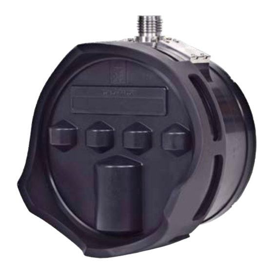
Page 15: Sonar Head
The Sonar Head’s black polyurethane transducer is delicate. Always keep the Guard Ring and protective cover over the transducer during installation and storage. Several different M3 Sonar models are available – your model may differ from the one shown here. For example, there are models with different depth ratings and materials, as well as models that include an integrated sound velocity sensor or high-frequency transducer. -
Page 16: Scope Of Supply
Additional optional items, page 16 Basic items provided with a standard delivery To assemble a complete M3 Sonar system you need all the system units. The main units you need are provided with the standard delivery. Additional items are required for operation. -
Page 17: Additional Required Items
The Sonar Head is designed to attach to a mounting bracket. You will need a mounting bracket that attaches to the M3 Sonar. The type of mounting bracket you need depends on how you intend to deploy the sonar. Depending on the application, you can mount the M3 Sonar on a remotely operated vehicle (ROV), with a Pole Mount on a surface vessel, or on a tripod. -
Page 18: Additional Optional Items
A Sonar Head with an integrated AML sound speed sensor is available from Kongsberg Discovery. Rotators Rotators are required if you wish to pan or tilt the M3 Sonar during operation. Several Kongsberg dual-axes and single-axis rotators are supported. 922-20007011/1.6... -
Page 19: General Safety Rules
• You must always turn off all power before installation or maintenance work on the M3 Sonar system. Use the main circuit breaker, and label the breaker with a warning sign that informs others that maintenance or installation work is in progress on the system. -
Page 20: Installation Requirements
-15% to +20% of the nominal voltage (except under fault conditions). Ethernet switch requirements Some M3 Sonar models (those with four wires for Ethernet) only support a data rate up to 100 Mbps. If you use an Ethernet switch with one of these models, make sure that your chosen model is able to auto-negotiate the network speed to 100 Mbps. - Page 21 – At least 2 meters (6.6 feet) from the path of radar beams. A typical radar beam spreads 20 degrees above and below the plane containing the radiating element. • Protect the M3 Sonar with a suitably rated fuse or circuit breaker. The power supply should be adequately filtered to minimize equipment exposure to high-voltage transients that may occur during engine start or when other high-power equipment is used on board of the vessel.
-
Page 22: Support Information
M3 Sonar Installation Manual Support information If you need technical support for your M3 Sonar you must contact your local dealer, or our support department. If you require maintenance or repair, contact your local dealer. You can contact us by phone at +1 604 464 8144, or by email at: support.vancouver@kd.kongsberg.com. -
Page 23: Preparations
Preparations Preparations Topics Installation summary, page 22 Tools and equipment required for installation, page 23 922-20007011/1.6... -
Page 24: Installation Summary
M3 Sonar Installation Manual Installation summary Installation of the M3 Sonar system requires a number of specific procedures and software settings. We recommend that at least two persons do the installation together. Context An overall installation procedure is provided. Note In order to obtain maximum safety and optimal performance, it is very important that the installation procedures in this manual are complied to. -
Page 25: Tools And Equipment Required For Installation
Specific tools and consumables you will need for the M3 Sonar installation are included in the supplied accessory kit. The following tools and items are required for the M3 Sonar installation and are not included in the standard delivery. You must purchase these items locally. -
Page 26: Installing The Sonar Processor
M3 Sonar Installation Manual Installing the Sonar Processor The Sonar Processor is the computer that controls the M3 Sonar system. It is a vital part of the M3 Sonar system. Prerequisites A suitable location for the computer must be defined prior to installation. This computer is intended to be installed inside in an area suitable for extended human habitation. - Page 27 Note Make sure that the chosen computer meets the M3 Sonar requirements. The design and construction must allow for marine use, and the computer must be able to withstand the movements and vibrations normally experienced on a vessel. Verify that you have easy access to cables and connectors, and that the computer can be installed in a safe and secure way.
- Page 28 When you connect the cables, make sure that they are all properly secured, and able to withstand the vibration and movements of the vessel. Result The M3 Sonar Sonar Processor is set up in a suitable location with the power supply and mouse connected. 922-20007011/1.6...
-
Page 29: Installing The Sonar Head
Installing the Sonar Head Installing the Sonar Head Topics Attaching the Sonar Head to a bracket, page 28 Installing the sacrificial anode, page 31 Mounting the Sonar Head, page 33 922-20007011/1.6... -
Page 30: Attaching The Sonar Head To A Bracket
• For high-shock environments, use fasteners with A286 Super Alloy. • You will need a mounting bracket that attaches to the M3 Sonar. The type of mounting bracket you need depends on how you intend to deploy the sonar. You can order a mounting bracket from Kongsberg Discovery, or you can make your own. - Page 31 Installing the Sonar Head Procedure Put the Sonar Head (A) with the transducer face down onto a stable flat surface. Observe the four mounting holes provided on the surface opposite to the transducer. If you have an aluminium Sonar Head, put the plastic isolation pad (B) on top of the Sonar Head, lining it up with the mounting holes.
- Page 32 M3 Sonar Installation Manual Result The Sonar Head is attached to a bracket, as shown in these examples. Related topics Installing the sacrificial anode, page 31 922-20007011/1.6...
-
Page 33: Installing The Sacrificial Anode
Sacrificial anodes are used to protect the transducer from corrosion. Prerequisites • To install the M3 Sonar system, you must have basic mechanical skills. We recommend that at least two persons do the installation together. • We assume that you are equipped with a standard set of tools. This tool set must comprise the normal tools for mechanical tasks. - Page 34 Procedure Observe the environment surrounding the aluminium M3 Sonar installation. Other devices made out of more noble metals, such as titanium for example, installed in close proximity may greatly accelerate corrosion of the aluminium housing.
-
Page 35: Mounting The Sonar Head
Prerequisites • To install the M3 Sonar system, you must have basic mechanical skills. We recommend that at least two persons do the installation together. • We assume that you are equipped with a standard set of tools. This tool set must comprise the normal tools for mechanical tasks. - Page 36 Sonar Head should not be aerated. Note When installing the M3 Sonar on an ROV, the Sonar Head should be tilted downward at around 8° to 15°. This tilted angle will improve the detection of the sea bottom at a short range.
- Page 37 Positive yaw means starboard turn. Measure the distance between the Sonar Head and your GPS or other position sensor. You will need to measure the distance in terms of the M3 Sonar coordinate system, as shown in the image. • X = to starboard •...
- Page 38 M3 Sonar Installation Manual Enter these measurements into the X, Y, and Z Offset fields on the Mounting Offsets page in the M3 software. 922-20007011/1.6...
-
Page 39: Cable Layout And Interconnections
Topics Read this first, page 38 Cable plan, page 39 List of M3 Sonar cables, page 40 Focal multiplexer compatibility table, page 41 Installing the M3 Sonar cables, page 42 Cable drawings and specifications, page 49 Basic cable requirements, page 56... -
Page 40: Read This First
Read this first Detailed information about cable specifications, termination and connectors is provided. Unless otherwise specified, all cables are supplied by Kongsberg Discovery as a part of the delivery. Kongsberg Discovery Canada Limited accepts no responsibility for damage to the system, or reduced operational performance, when this is caused by improper wiring. -
Page 41: Cable Plan
The cables are part of the delivery with the main units. This diagram shows three deployment examples. Basic system interconnection (for setting up a bench test, for example) VDSL system interconnection Remotely Operated Vehicle (ROV) system interconnection Sonar Processor Mouse M3 Power Supply 922-20007011/1.6... -
Page 42: List Of M3 Sonar Cables
DC connector on M3 M3 Power Supply Cable Ethernet Sonar Processor Telemetry connector (RJ-45 female socket) on M3 Cable / Modem / Junction Box Ethernet M3 Cable Power and telemetry Sonar Head connectors on Ethernet M3 Cable RJ11 patch cable... -
Page 43: Focal Multiplexer Compatibility Table
Cable layout and interconnections Focal multiplexer compatibility table If you are installing the M3 Sonar on a Remotely Operated Vehicle (ROV), make sure that your Focal fiber-optic multiplexer is supported. In general, any multiplexer will work over four wires if gigabit Ethernet negotiation has been disabled. -
Page 44: Installing The M3 Sonar Cables
Replacing the o-ring in the sonar cable connector A cable with a 10-pin cable connector connects to the Sonar Head. When installing the M3 Sonar, you must check if the o-ring is properly installed. If the o-ring is missing or damaged, it will need to be replaced. - Page 45 Cable layout and interconnections The following tools and consumables are not included and must be purchased locally. • Dove-tail O-ring Installation Tool (DOIT) • O-ring pick tool • O-ring grease • Swabs • Isopropyl Alcohol 922-20007011/1.6...
- Page 46 M3 Sonar Installation Manual Procedure Remove the o-ring from the Cable Connector Plug. Use the Parker o-ring picks to extract the o-rings from the Cable Connector Plugs and Flanged Connector Receptacle. Clean the o-ring surface with Q-Tips and Isopropyl Alcohol.
- Page 47 Cable layout and interconnections Grease the replacement o-ring with a small amount of o-ring grease. Fit the o-ring onto the DOIT and slide it to the end. 922-20007011/1.6...
- Page 48 M3 Sonar Installation Manual Using the DOIT, fit the o-ring back onto the Cable Connector Plug or Flanged Connector Receptacle. Install the o-ring in the Cable Connector Plug by aligning the key and pressing into the connector. Rotating the DOIT when pulling it out can help ensure the o-ring stays in place.
-
Page 49: Replacing The Retaining Ring In A Dummy Plug
M3 Sonar, check if the retaining ring is damaged or missing — especially if you have been using your M3 Sonar in the field. The retaining ring is a small steel part that can break over a prolonged period through corrosion. - Page 50 M3 Sonar Installation Manual Insert the retaining-ring plier tips into the two holes in your replacement retaining ring. Push the tips in as far as possible into the retaining-ring holes before squeezing the plier handles. Using minimal pressure, spread the retaining ring slightly apart and slide it over the end of the dummy plug.
-
Page 51: Cable Drawings And Specifications
Cable layout and interconnections Cable drawings and specifications Topics Ethernet cable, page 50 Sonar Head - SEA CON MINK-10-CCPL: Power and Ethernet, page 51 Sonar Head - SEA CON MINK-10-CCPL:Power, Ethernet, 1PPS, and Sync, page 51 Sonar Head - SEA CON MIND-4-CCP: Synchronization, page 52 Sonar Head - SeaNet: Power and Telemetry, page 52 Sonar Head - SEA CON MINK-10-CCPL: Power, Ethernet 10/100, and VDSL, page 53 Sonar Head - SubConn MCOM6F: Power and Ethernet, page 53... -
Page 52: Ethernet Cable
M3 Sonar Installation Manual Ethernet cable Most high speed connections are made using Ethernet cables. The M3 Sonar must use T568B termination for RJ45 connections on both ends of the cable. Local Ethernet connection Connection on external network device Ethernet cables are available commercially in different lengths, colours and categories. -
Page 53: Sonar Head - Sea Con Mink-10-Ccpl: Power And Ethernet
Cable layout and interconnections Sonar Head - SEA CON MINK-10-CCPL: Power and Ethernet This rugged cable is intended for underwater use and includes both power and Ethernet telemetry connections for the Sonar Head. The underwater connector is a dry-mate style and must be mated or unmated at the surface. -
Page 54: Sonar Head - Sea Con Mind-4-Ccp: Synchronization
Sonar Head - SeaNet: Power and Telemetry This rugged cable is intended for underwater use and includes both power and Ethernet telemetry connections for the Sonar Head. The SeaNet connector is only available on the 4000 m version of the M3 Sonar. Pin Functions •... -
Page 55: Sonar Head - Sea Con Mink-10-Ccpl: Power, Ethernet 10/100, And Vdsl
Cable layout and interconnections Sonar Head - SEA CON MINK-10-CCPL: Power, Ethernet 10/100, and VDSL This rugged cable is intended for underwater use and includes both power and Ethernet telemetry connections for the Sonar Head. The underwater connector is a dry-mate style and must be mated or unmated at the surface. -
Page 56: Sonar Head - Subconn Dil13F: Power And Ethernet
: BI_DA+ (orange/white) / TX+ Pin 5 • : BI_DA- (white) / TX- Pin 6 • : BI_DB+ (green/white) / RX + Pin 7 • : BI_DB- (white) / RX- Pin 8 Note The M3 Sonar supports auto MDI/MDI-X. 922-20007011/1.6... -
Page 57: Sonar Head - Subconn Mcbh4Mti: Synchronization
Cable layout and interconnections Sonar Head - SubConn MCBH4MTi: Synchronization This is an optional cable only used if you have purchased a Sonar Head that supports synchronization. Pin Functions • : DGND (black) Pin 1 • : PRI_SYNC (white) Pin 2 •... -
Page 58: Basic Cable Requirements
M3 Sonar Installation Manual Basic cable requirements It is very important that all systems cables are installed correctly. All cables must be properly supported and protected, and all relevant precautions must be made to prevent unwanted noise. Topics Ethernet cable installation, page 57... -
Page 59: Ethernet Cable Installation
Cable layout and interconnections Ethernet cable installation All cable connections may have to be made in accordance with the guidelines laid down by the local electrical code. Alien crosstalk Alien crosstalk is where the signal from one cable interferes with the signal being carried by another. -
Page 60: Radio Frequency Interference
M3 Sonar Installation Manual Ground loops Ground loop noise is caused when the equipment is grounded at two or more points that have different potentials. This inconsistency creates a current path causing electromagnetic interference (EMI). This interference appears as rings in the sonar view (usually at a constant range). -
Page 61: Grounding Of System Cables
Cable layout and interconnections Grounding of system cables All metallic cable coverings (armour, metallic sheathing and other protection) must be electrically connected to the vessel's hull at both ends except in the case of final sub-circuits where they should be connected at the supply end only. Grounding connections should be made using a conductor which has a cross-sectional area appropriate for the current rating of the cable, or with a metal clamp which grips the metallic covering of the cable and is bonded to the hull of the vessel. -
Page 62: Setting To Work
Setting to work Topics Setting to work summary, page 61 Making sure that the M3 Sonar is ready for operational use, page 62 Turning on the M3 Sonar system, page 66 Configuring the M3 Sonar system for normal operation, page 68... -
Page 63: Setting To Work Summary
Setting to work summary Once all the hardware units have been installed, and all the cables have been connected, the M3 Sonar system can be turned on for the first time and set to work. Prerequisites • The system units have all been installed according to the instructions provided. -
Page 64: Making Sure That The M3 Sonar Is Ready For Operational Use
Making sure that all M3 Sonar system cables are properly connected, page 64 Making sure that the operating power is correct The M3 Sonar system operates on AC power from the vessel’s mains supply. Before you connect AC power to any system unit, you must make sure that the voltage is correct. - Page 65 Verify that there is adequate ventilation to avoid overheating. Perform a close visual inspection of the Power Supply. Verify that the unit is suitably oriented to enable easy connection to the M3 Sonar cable and for maintenance. Ensure the anode and isolation pad are properly installed to prevent the Sonar Head’s aluminium housing from corroding.
-
Page 66: Making Sure That All M3 Sonar System Cables Are Properly Connected
M3 Sonar Installation Manual Make sure that the Guard Ring on the M3 Sonar Head is oriented correctly so that the Kongsberg logo is in the centre, above the middle connector. Note Improper alignment of the guard ring may reduce sonar beam coverage and decrease bottom coverage. - Page 67 Setting to work Procedure For each cable that is in used on the M3 Sonar: Verify that the cable has been installed according to the cable plan. Verify that the connections made at each end of the cable are correct.
-
Page 68: Turning On The M3 Sonar System
Cable plan, page 39 Turning on the M3 Sonar system To use the M3 Sonar system, you must turn it on. You must first turn on the display and the computer. After this you can start the M3 software. Prerequisites •... - Page 69 Setting to work Log in to Windows. On the Sonar Processor desktop, double-click the M3 Sonar icon to start the software. Once the program has started, observe that the display presentation fills the entire screen. The software starts up using many of the same settings as the last time you used it.
-
Page 70: Configuring The M3 Sonar System For Normal Operation
M3 Sonar Installation Manual Configuring the M3 Sonar system for normal operation Topics Setting the Sonar Processor to High Performance, page 69 Installing the M3 software, page 70 Defining the IP address on the computer's network adapter, page 71 922-20007011/1.6... -
Page 71: Setting The Sonar Processor To High Performance
Setting to work Setting the Sonar Processor to High Performance To avoid slowdowns or disruptions while running the sonar, ensure your Sonar Processor is using all of its processing power and does not go to sleep. Prerequisites ® This procedure is made for the Microsoft 64-bit Windows 10 operating system. -
Page 72: Installing The M3 Software
Follow the installation wizard’s instructions and select Standard Installation. Note Use the Dual-M3 on Same PC option only if you are using two M3 Sonars. Selecting this option will install two separate copies of the software, with each copy having its own settings. -
Page 73: Defining The Ip Address On The Computer's Network Adapter
As long as you do not change the Sonar Processor to another computer, or replace the serial adapter in your Sonar Processor, you will only need to do this once. Procedure On the computer, close the M3 software. Open the dialog box. -
Page 74: Testing The Operating Functionality Of The M3 Sonar System
M3 Sonar Installation Manual Testing the operating functionality of the M3 Sonar system Topics Testing operation of the Sonar Head, page 72 Testing the Sonar Head telemetry, page 74 Testing operation of the Sonar Head You can test the operation of the Sonar Head by confirming that sonar data is being... - Page 75 Connection Status Make sure that all items listed under the M3 Sonar show check marks. If any items are shown with an “X” in a red circle, it usually means the device has failed to connect. Disconnect and make sure that no sensors have failed.
-
Page 76: Testing The Sonar Head Telemetry
Prerequisites • For this test you will need the Sonar Head connected to the Sonar Processor and powered on. • The M3 software must be running. • This procedure is made for the Microsoft ® 64-bit Windows 10 operating system. It ®... - Page 77 The ping rate is normally taken from the sonar application or range setting. If the estimated available bandwidth is less than the bandwidth required by the sonar application/range, the M3 software reduces the ping rate to compensate. Note The update rate is the number of times the sonar view is updated per second. The displayed ping rate may be different from the update rate because the system might be impacted by other processes.
- Page 78 If the Network utilization is less than 80%, disconnect the sonar, close all other programs, then reconnect the sonar. In general, make sure that your network environment supports the required link speed. In the M3 software, look for any messages in the window. Output Messages Make sure there are no lost packets.
-
Page 79: Turning Off The M3 Sonar System
Setting to work Turning off the M3 Sonar system The M3 Sonar is not provided with an on/off switch. Context When you do not use the M3 Sonar system, turn it off. Procedure → If you are running the sonar, click in the M3 software. -
Page 80: Drawing File
Sonar Head with integrated sound speed sensor outline dimensions, page 85 About the drawings in the drawing file Relevant drawings related to the installation and/or maintenance of the M3 Sonar are provided for information purposes only. The drawings are not to scale. Unless otherwise specified, all measurements are in inches. -
Page 81: 500 M Sonar Head Outline Dimensions
Drawing file 500 m Sonar Head outline dimensions 922-20007011/1.6... - Page 82 M3 Sonar Installation Manual 922-20007011/1.6...
- Page 83 Drawing file 922-20007011/1.6...
-
Page 84: 4000 M Sonar Head Outline Dimensions
M3 Sonar Installation Manual 4000 m Sonar Head outline dimensions 922-20007011/1.6... - Page 85 Drawing file 922-20007011/1.6...
- Page 86 M3 Sonar Installation Manual 922-20007011/1.6...
-
Page 87: Sonar Head With Integrated Sound Speed Sensor Outline Dimensions
Drawing file Sonar Head with integrated sound speed sensor outline dimensions 922-20007011/1.6... - Page 88 M3 Sonar Installation Manual 922-20007011/1.6...
- Page 89 Drawing file 922-20007011/1.6...
-
Page 90: Technical Specifications
M3 Sonar Installation Manual Technical specifications Topics Introduction to technical specifications, page 89 Interface specifications, page 90 Performance specifications, page 93 Mechanical specifications, page 97 Power requirements, page 99 Environmental requirements, page 100 Minimum computer requirements, page 100 922-20007011/1.6... -
Page 91: Introduction To Technical Specifications
Technical specifications Introduction to technical specifications These technical specifications summarize the main functional and operational characteristics of the M3 Sonar Multibeam sonar. They also provide information related to power requirements, physical properties and environmental conditions. Note At Kongsberg Discovery, we are continuously working to improve the quality and performance of our products. -
Page 92: Interface Specifications
M3 Sonar Installation Manual Interface specifications The M3 Sonar system will interface with peripheral systems and sensors using standard and/or proprietary datagram formats. Supported datagram formats for GPS (position) information The M3 Sonar system supports the following datagram formats for position information: •... - Page 93 This is a third-party proprietary datagram format for heading, speed, and motion. It was created by iXSea (http://www.ixblue.com) for use with their Octans gyrocompass. Supported datagram formats for motion information The M3 Sonar system supports the following datagram formats from a motion sensor: • Teledyne TSS1 Teledyne TSS1 is a proprietary datagram format for heave, roll and pitch compensation.
- Page 94 Therefore, data body size may change depending upon the mode. • .ALL This is the proprietary Kongsberg EM series datagram format. The M3 software can output this data format to be compatible with third-party post-processing software. Synchronization •...
-
Page 95: Performance Specifications
• Computer Time Sync If ZDA is configured, the M3 software will use the time in the ZDA message to synchronize the computer clock automatically in the background. However, you may need to run the M3 software as an administrator (right-click on the icon and select... - Page 96 The selection of sonar applications presented in the menu depends Sonar Applications on the current Sonar Head frequency. The M3 software will automatically detect the frequency of your Sonar Head and display only the applicable sonar applications. Variable Vertical Beamwidth (Imaging) mode — 500 kHz •...
- Page 97 Technical specifications Imaging mode — 700 kHz • : 140° Horizontal Field of View • : 30° Vertical Beamwidth • : 1.0° Angular Resolution • : up to 40 Hz Update rate Imaging mode — 950 kHz • : 140° Horizontal Field of View •...
- Page 98 M3 Sonar Installation Manual Profiling mode — 1200 kHz • : 75° View angle • : 1.1° x 1.2° Resolution • : 70 m Max Range • : 256 No. of Beams Profiling mode — 1400 kHz • : 45°...
-
Page 99: Mechanical Specifications
Sonar Head receive firmware file (.RXF) and the Sonar Head software file (.ASW). You do not need to upgrade the Sonar Head transmit firmware file (.TXF). AML SVT Xchange sound speed sensor A Sonar Head with an integrated AML sound speed sensor is available from Kongsberg Discovery. •... - Page 100 Optional connector models • : SEA CON ® , MIND-4-FCR Synchronization • : Alstom Seanet (4000 m M3 Sonar only) 100BaseTX Ethernet and Power • : SubConn MCBHRA6MSS (500 m M3 Sonar only) 100BaseTX Ethernet and Power High-frequency Sonar Head •...
-
Page 101: Power Requirements
• : 27 Mbps (measured on Belkin 1353A) 1000 m (3300 foot) cable AML SVT Xchange sound speed sensor A Sonar Head with an integrated AML sound speed sensor is available from Kongsberg Discovery. • : 11000 m Depth rating •... -
Page 102: Environmental Requirements
Operating temperature Minimum computer requirements Although a computer can be ordered from Kongsberg Discovery as a part of the M3 Sonar system delivery, it is also possible to purchase one locally. If you purchase a computer locally, make sure that the chosen model meets the functional and technical requirements. - Page 103 14,000 or more (passmark.com). PassMark Software is a Windows computer performance benchmarking utility. Computers with a CPU score of 14,000 or higher have been tested with the M3 Sonar. Lower-scoring computers may not perform well, resulting in a slow GUI response, slower ping rates, or dropped pings.
- Page 104 M3 Sonar Installation Manual The computer may offer video output on several formats. Investigate your options before you purchase a display. • : The screen size depends on personal and/or operational Physical screen size preferences. 922-20007011/1.6...
-
Page 105: Equipment Handling
Equipment handling Equipment handling Topics Transporting Kongsberg Discovery equipment, page 104 Lifting units and transportation boxes, page 105 Inspection of units and transportation boxes after arrival, page 106 Specifications for storage prior to installation or use, page 107 Unpacking standard parts and units, page 108 Repacking the Sonar Head, page 109 922-20007011/1.6... -
Page 106: Transporting Kongsberg Discovery Equipment
In the absence of other information, no other boxes must be stacked on top of it. Handle all boxes and units with care. Note Due to the nature of Kongsberg Discovery’s products, and the extensive use of delicate electronic parts, all units and boxes must be regarded and handled as fragile equipment. -
Page 107: Lifting Units And Transportation Boxes
Equipment handling Lifting units and transportation boxes Some of the boxes used to hold equipment units may be heavy. Use caution when lifting. Prerequisites Units and boxes may be heavy. Make sure that you have the necessary equipment required for lifting heavy items. Persons using the lifting equipment must be skilled and have the relevant certificate(s). -
Page 108: Inspection Of Units And Transportation Boxes After Arrival
M3 Sonar Installation Manual Handle all units and boxes with care. Note Due to the nature of Kongsberg Discovery’s products, and the extensive use of delicate electronic parts, all units and boxes must be regarded and handled as fragile equipment. -
Page 109: Specifications For Storage Prior To Installation Or Use
Equipment handling Specifications for storage prior to installation or use Whenever a system, a unit or a spare part has been delivered, it may be subjected to long-time storage before installation and use. You must meet certain specifications during this storage period. It is essential that you preserve and store the equipment so that it does not threaten health, environment or personal injury. -
Page 110: Unpacking Standard Parts And Units
Context This procedure provides the basic tasks of unpacking units (main unit, spare parts etc) from boxes shipped from Kongsberg Discovery. Note If the unit in question is not unpacked for immediate use, you may consider storing it unopened in its original box. -
Page 111: Repacking The Sonar Head
Describe the damage, and collect photographic evidence if possible. Return the inspection report to Kongsberg Discovery as soon as possible. Place the box on a stable work bench or on the floor with the top of the box facing upwards. - Page 112 M3 Sonar Installation Manual Caution The Sonar Head’s black polyurethane transducer is delicate. Always keep the Guard Ring and protective cover over the transducer during installation and storage. Store the Sonar Head in a cool, dry location away from ozone sources (such as electric motors or welders).
- Page 113 Pack the cables and accessory kits into the side pocket (B) of the case. Note If you did not order a Sonar Processor from Kongsberg Discovery, the USB flash drive goes here too. Pack the Quick Start Guide and any other documentation you may have into the back pocket of the case (C).
- Page 114 M3 Sonar Installation Manual Index 1000Base-T grounding ..........59 Ethernet cable ..........50 physical protection........58 radio frequency interference......58 cable terminations requirements ..........59 cables about connection requirements ........ 59 comments ..........7 grounding requirements......... 59 constructive criticism........7 list ............
- Page 115 Kongsberg Discovery equipment ..104 requirements ..........100 Turning off the M3 Sonar system...... 77 equipment handling........103 Turning on the M3 Sonar system ...... 66 inspection ..........106 unpack standard parts and units...... 108 lifting units and transportation boxes ....105 verify that all cables are properly connected ..
- Page 116 Defining the IP address on the network Turning off the M3 Sonar system...... 77 adapter ........... 71 Turning on the M3 Sonar system ...... 66 unpacking standard parts and units ....108 verifying that all cables are properly connected ..........64...
- Page 117 Index this publication ..........7 purpose ............ 13 repacking..........109 testing ............. 72 Sonar Processor configuring..........69 radio frequency interference installing ..........24 cable requirements........58 introduction ..........12 registered trademarks........7 overview ..........12 repacking purpose ............ 12 Sonar Head ..........109 sound speed required items datagram formats ........
- Page 118 ......23 transportation of delicate and fragile equipment ....104 Turning off the M3 Sonar system......77 Turning on the M3 Sonar system ......66 units standard tools for installation ......23 verify correct installation ....... 62 unpacking standard parts and units .......
- Page 120 ©2024 Kongsberg Discovery Canada Limited...
Need help?
Do you have a question about the M3 and is the answer not in the manual?
Questions and answers