Table of Contents
Advertisement
Quick Links
Download this manual
See also:
Reference Manual
Advertisement
Table of Contents

Subscribe to Our Youtube Channel
Related Manuals for Kongsberg Flexview


Summary of Contents for Kongsberg Flexview
- Page 1 Installation Manual Flexview Multibeam Sonar...
- Page 3 Release 1.0 This manual provides you with the basic information required to install the Kongsberg Flexview Multibeam sonar. The information is intended for personnel with basic mechanical skills. For information about the practical use of the product, refer to the Kongsberg Flexview Reference manual.
- Page 4 No part of this document may be copied or reproduced in any form or by any means, and the information contained within it is not to be communicated to a third party, without the prior written consent of Kongsberg Mesotech Limited.
-
Page 5: Table Of Contents
Support information ......................19 PREPARATIONS ................. 20 Installation summary......................21 Tools and equipment required for Flexview installation ............22 INSTALLING THE SONAR PROCESSOR ........23 INSTALLING THE SONAR HEAD ..........26 Attaching the Sonar Head to a bracket ................. 27 Installing the sacrificial anode .................... - Page 6 Cable connections and terminations................74 SETTING TO WORK ..............75 Setting to work summary ...................... 76 Verifying that the Flexview is ready for operational use ............77 Verifying that operational power is correct ..............77 Verifying that all hardware is properly installed ............78 Verifying that all Flexview cables are properly connected .........
- Page 7 Power requirements ......................107 Environmental requirements....................108 Minimum computer requirements..................108 EQUIPMENT HANDLING............110 Transporting Kongsberg Mesotech equipment ..............111 Lifting units and transportation boxes .................112 Inspection of units and transportation boxes after arrival............113 Specifications for storage prior to installation or use............114 Unpacking standard parts and units ..................115...
- Page 8 Flexview 922-20207011/1.0...
-
Page 9: About This Manual
We assume that you are familiar with the basic acoustic principles of sound in water. Familiarity with multibeam echo sounder and survey techniques are also recommended. License information The Flexview Software is included with the Flexview system and updates are available free of charge and can be downloaded from: http://www.km.kongsberg.com/mesotechsoftware. Software version This Flexview Installation Manual complies with Flexview software version 1.0. -
Page 10: Flexview
Flexview Installation Manual Flexview Topics System description, page 9 System diagram, page 10 System units, page 11 Scope of supply, page 14 General safety rules, page 17 Installation requirements, page 18 Support information, page 19 922-20207011/1.0... -
Page 11: System Description
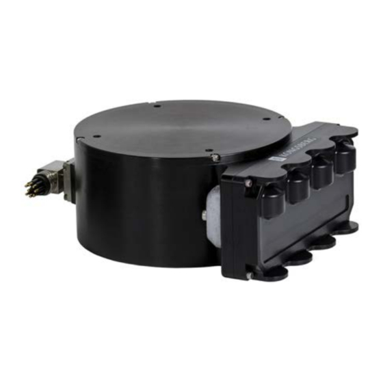
The removable transducer on the Flexview is the first of its kind, offering field replacement of a damaged transducer in the unlikely event of a catastrophic impact. This innovative design also allows for transducer configurations to be exchanged, depending on the job being performed. -
Page 12: System Diagram
Flexview Installation Manual System diagram The system diagram identifies the main components of a basic Flexview system. Only the main connections between the units are shown. Detailed interface capabilities and power cables are not shown. ROV Topside Unit Sonar Processor... -
Page 13: System Units
Flexview System units Topics Sonar Processor, page 12 Power supply, page 12 Sonar Head, page 13 922-20207011/1.0... -
Page 14: Sonar Processor
In this publication, the computer is referred to as the Sonar Processor. The Sonar Processor contains the operational software, and offers the user interface that allows you to control the Flexview. It is a vital part of the Flexview Multibeam sonar. The Sonar Processor runs the Flexview software that... -
Page 15: Sonar Head
Prolonged exposure to ultra-violet rays and excessive heat may damage the surface of the polyurethane transducer face. Always store the Flexview in the provided equipment case when not in use. If the Flexview is mounted on an ROV, cover the transducer when not in use. -
Page 16: Scope Of Supply
Additional optional items, page 15 Basic items provided with a standard delivery To assemble a complete Flexview system, you will need a set of system units. The main units required are provided with the standard delivery. Other required units may be purchased from Kongsberg Mesotech or obtained locally. -
Page 17: Additional Required Items
Flexview items.You can also purchase these items from your dealer, agent or local supplier. Sonar Processor The Sonar Processor is not a standard part of the Flexview delivery. A suitable computer must be purchased locally. If you purchase a computer locally, make sure that the chosen model meets the functional and technical requirements. - Page 18 Secondary display This is a commercial item that can be purchased locally. Any commercial display can be used with the Flexview Multibeam sonar, provided that the display meets the minimum requirements. The chosen display must be designed for maritime use, and it must meet the minimum performance specifications. You must also make sure that the chosen display supports the video formats provided by the Sonar Processor.
-
Page 19: General Safety Rules
• You must always switch off all power before installation or maintenance work on the Flexview system. Use the main circuit breaker, and label the breaker with a warning sign that informs others that maintenance or installation work is in progress on the system. -
Page 20: Installation Requirements
Employ the following recommendations to ensure the best EMC performance: • Use only Kongsberg-specified cables and check that any ferrite suppression filters fitted on the cables are installed as per the installation drawings. Suppression ferrites are important for minimizing electromagnetic interference. -
Page 21: Support Information
– At least 2 meters (6.6 feet) from the path of radar beams. A typical radar beam spreads 20 degrees above and below the plane containing the radiating element. • Protect the Flexview with a suitably rated fuse or circuit breaker. The power supply should be adequately filtered to minimize equipment exposure to high-voltage transients that may occur during engine start or when other high-power equipment is used on board of the vessel. -
Page 22: Preparations
Flexview Installation Manual Preparations Topics Installation summary, page 21 Tools and equipment required for Flexview installation, page 22 922-20207011/1.0... -
Page 23: Installation Summary
An overall installation procedure is provided. Note In order to obtain maximum safety and Flexview performance, it is very important that the installation procedures in this manual are complied to. You must do the tasks in the order they are described. -
Page 24: Tools And Equipment Required For Flexview Installation
Specific tools and consumables you will need for the Flexview installation are included in the supplied accessory kit. The following tools and items are required for the Flexview installation and are not included in the standard delivery. You must purchase these items locally. -
Page 25: Installing The Sonar Processor
Installing the Sonar Processor Installing the Sonar Processor The Sonar Processor is the computer that controls the Flexview system. It is a vital part of the Flexview Multibeam sonar. Prerequisites A suitable location for the computer must be defined prior to installation. This computer is intended to be installed inside in an area suitable for extended human habitation. - Page 26 For installation of a commercial computer, refer to the manual supplied by the manufacturer. Note Make sure that the chosen computer meets the Flexview requirements. The design and construction must allow for marine use, and the computer must be able to withstand the movements and vibrations normally experienced on a vessel.
- Page 27 When you connect the cables, make sure that they are all properly secured, and able to withstand the vibration and movements of the vessel. Result The Flexview Sonar Processor is set up in a suitable location with the power supply and mouse connected. 922-20207011/1.0...
-
Page 28: Installing The Sonar Head
Flexview Installation Manual Installing the Sonar Head Topics Attaching the Sonar Head to a bracket, page 27 Installing the sacrificial anode, page 30 Mounting the Sonar Head, page 32 922-20207011/1.0... -
Page 29: Attaching The Sonar Head To A Bracket
Depending on the chosen installation method, additional tools may be required. • You will need a mounting bracket that attaches to the Flexview. The type of mounting bracket you need depends on how you intend to deploy the sonar. - Page 30 Prolonged exposure to ultra-violet rays and excessive heat may damage the surface of the polyurethane transducer face. Always store the Flexview in the provided equipment case when not in use. If the Flexview is mounted on an ROV, cover the transducer when not in use.
- Page 31 Installing the Sonar Head Procedure Put the Sonar Head (D) onto a stable, flat surface. Observe the four mounting holes provided on the top surface of the Sonar Head. Put the plastic isolation pad (C) on top of the Sonar Head, lining it up with the mounting holes.
-
Page 32: Installing The Sacrificial Anode
Sacrificial anodes are used to protect the Sonar Head from corrosion. Prerequisites • To install the Flexview, you must have basic mechanical skills. • We assume that you are equipped with a standard set of tools. This tool set must comprise the normal tools for mechanical tasks. - Page 33 Installing the Sonar Head Procedure Observe the environment surrounding the aluminium Flexview installation. Other devices made out of more noble metals, such as titanium for example, installed in close proximity may greatly accelerate corrosion of the aluminium housing. Install the anode (!) using a stainless steel fastener.
-
Page 34: Mounting The Sonar Head
Prolonged exposure to ultra-violet rays and excessive heat may damage the surface of the polyurethane transducer face. Always store the Flexview in the provided equipment case when not in use. If the Flexview is mounted on an ROV, cover the transducer when not in use. - Page 35 In addition, the water in front of the Sonar Head should not be aerated. When installing the Flexview on an ROV, tilting the Sonar Head down around 8° to 15° may improve detection of the sea bottom at short range.
- Page 36 Measure the distance between the Sonar Head and your GPS or other position sensor. You will need to measure the distance in terms of the Flexview coordinate system, as shown in the image. • The coordinate system’s Master Reference point is always assumed to be your GPS or position sensor reference point.
-
Page 37: Cable Layout And Interconnections
Topics Read this first, page 36 Cable plan, page 37 VDSL cable plan, page 39 List of Flexview cables, page 40 Focal multiplexer compatibility table, page 41 Installing the Flexview cables, page 42 Cable drawings and specifications, page 66 Basic cable requirements, page 71... -
Page 38: Read This First
Kongsberg Mesotech Limited accepts no responsibility for damage to the system, or reduced operational performance, when this is caused by improper wiring. Note Before you install or maintain the Flexview cables, make sure that the AC mains circuit breaker for the system is switched off. 922-20207011/1.0... -
Page 39: Cable Plan
The cables are part of the delivery with the main units. This diagram shows two deployment examples. Basic system interconnection (for setting up a bench test, for example) Remotely Operated Vehicle (ROV) system interconnection Sonar Processor Mouse Flexview Power Supply 922-20207011/1.0... - Page 40 Flexview Installation Manual Sonar Head ROV Topside Unit ROV Controller ROV Junction Box / MUX Note When deployed on an ROV, the ROV Junction Box normally supplies power to the Sonar Head (12 to 36 VDC). 922-20207011/1.0...
-
Page 41: Vdsl Cable Plan
The cables are part of the delivery with the main units. This diagram shows two deployment examples. Basic system interconnection (for setting up a bench test, for example) Remotely Operated Vehicle (ROV) system interconnection Sonar Processor Mouse Flexview Power Supply Sonar Head VDSL Modem ROV Topside Unit 922-20207011/1.0... -
Page 42: List Of Flexview Cables
Head (12 to 36 VDC). Related topics Installing the VDSL cables, page 64 List of Flexview cables A set of cables is required to connect the Flexview units to each other, and to the relevant power source(s). Cable Description From... -
Page 43: Focal Multiplexer Compatibility Table
Cable layout and interconnections Focal multiplexer compatibility table If you are installing the Flexview on a Remotely Operated Vehicle (ROV), make sure that your Focal fiber-optic multiplexer is supported. In general, any multiplexer will work over four wires if gigabit Ethernet negotiation has been disabled. -
Page 44: Installing The Flexview Cables
Flexview Installation Manual Installing the Flexview cables Topics Mating the SubConn ® cable connector, page 42 Splicing the Flexview cable whip, page 45 Installing the VDSL cables, page 64 Mating the SubConn ® cable connector The SubConn ® underwater connectors are a wet-mate style and can be mated or unmated at the surface or underwater. - Page 45 Cable layout and interconnections Grease the connectors with Molykote 44 Medium. Apply a layer of grease corresponding to a minimum 1/10 of socket depth (A) to the female connector. If mating underwater, more grease is required — about 1/3 of socket depth (B). Completely cover the inner edge of all sockets.
- Page 46 Flexview Installation Manual Related topics Sonar Head - SubConn MCIL8F: Power and Ethernet, page 69 922-20207011/1.0...
-
Page 47: Splicing The Flexview Cable Whip
Cable layout and interconnections Splicing the Flexview cable whip You will need to splice the supplied cable whip to the cable leading to your ROV junction box. It is possible to splice the spare 50-ft (or 15-ft) test cable provided with your system, but you risk intermittent telemetry errors if the cable is not terminated correctly. - Page 48 Flexview Installation Manual A vice, clamp, or tweezers to hold the wires to be heated. Molykote 44 Medium grease (necessary for SubConn cable connectors only) ™ Scotchcast Flexible Power Cable Inline Splicing Kit 82-F1 A cable tester, such as the Fluke Networks CIQ-100 CableIQ Qualification Tester...
- Page 49 Cable layout and interconnections Adjust the height of the cable stripper blade so that it will slice through the cable jacket only, and not the inner wires. Spiral the cable stripper around the cable in a circular motion to slice the cable jacket.
- Page 50 Flexview Installation Manual Use the side cutters to cut off the sliced cable jacket. Prepare the wires on both cables for soldering. 922-20207011/1.0...
- Page 51 Cable layout and interconnections Peel and cut off the plastic wrapper (A) from around the inner wires. Remove the water block — the brown glue-like substance (B) — from between the wires. Pull the water block off by hand. It should just crumble off. Observe how the coloured Ethernet pairs are twisted around each other and how the twist ratio is different for each Ethernet pair.
- Page 52 Flexview Installation Manual Remove the additional rubber insulation wrapped around each Ethernet pair. To avoid severing the wires, make a small incision with the side cutters, then peel off the rest by hand. Using the side cutters, cut each Ethernet pair to a different length so that there will be a 1/4″...
- Page 53 Cable layout and interconnections Use the wire strippers to strip back approximately 1/4″ of insulation from each wire. Make sure you match the gauge of the wire with the appropriately-sized hole on the wire stripper or you may cut both insulation and wire. Solder the wires and cover the wire splices with heat shrink.
- Page 54 Flexview Installation Manual Using the soldering iron, apply a light layer of solder to the ends of the wires. Called “tinning the tips”, this process improves conductivity and makes soldering both quicker and easier. Using the side cutters, cut the heat-shrink tubes to the right size.
- Page 55 Cable layout and interconnections Select one of the cables and slide the heat-shrink tubes over the exposed wires. Move the heat-shrink tubes as far over as you can so that you don’t accidentally shrink them when soldering in the next step. Try to twist the Ethernet pairs as they were originally.
- Page 56 Flexview Installation Manual Using the soldering iron, solder the appropriate wires together. Use the damp sponge to wipe off excess solder. A vice, clamp, or tweezers helps to hold the wires in place. Move the heat-shrink tubes over to the middle of each join.
- Page 57 Cable layout and interconnections Mate the appropriate test connectors to either end of the spliced cable. Note SubConn cable connectors must be greased before mating (grease at least 1/10 of the socket depth on the female connector). For Seacon connectors, make sure that the o-ring is not missing. Line up the pins and tighten the locking sleeve.
- Page 58 Flexview Installation Manual Plug the other RJ45 connector on the test connector (on the other end of the spliced cable) into the RJ45 socket on the top of the cable tester. Press the green button to turn on the cable tester.
- Page 59 Cable layout and interconnections Observe the test results and make sure that the 100BASE-TX test passed. Turn off the cable tester and unplug the test connector. Pot the cable splice with the splicing kit. Unpack the contents of the splicing kit. WARNING Read all the Material Safety Data Sheet information supplied with the splicing kit before using.
- Page 60 Flexview Installation Manual Using the abrasive cloth, scuff the ends of the cable outer jackets. Using the utility knife, cut the tapered ends of the mold to fit the cable diameter. Tape the spliced wires together to keep them in position.
- Page 61 Cable layout and interconnections Place the cable into the mold with the splice at the centre. Close the mold, then tape the ends of the mold onto the cable. Cut a slit into the top of the cardboard carton and place the mold’s hinge into it. The carton will hold the splice in position for compound pouring.
- Page 62 Flexview Installation Manual • Knead the pouch to mix the contents. Important Mix until the colour is completely uniform. Do not exceed one minute. • Squeeze the compound away from the corners of the pouch. 922-20207011/1.0...
- Page 63 Cable layout and interconnections Cut off a corner of the pouch and immediately pour the compound into the mold. Fill the mold until the compound reaches the mold’s filler spout. Allow the compound to cure (from 16 to 36 hours, depending on the room temperature).
- Page 64 Flexview Installation Manual Remove the mold. Start by separating the mold halves at the filler spout. Trim off the excess compound from the filler spout by cutting it off at the base. 922-20207011/1.0...
- Page 65 Cable layout and interconnections Test the electrical connections again using the cable tester and make sure that it is ready for use. 922-20207011/1.0...
-
Page 66: Installing The Vdsl Cables
DIP switches two, three, and four have no function in CPE mode. When using the Flexview cable with a breakout box, connect the supplied RJ11 patch cable from the four-pin Sync/VDSL Bulgin connector on the breakout box to the RJ11 connector (A) on the modem. - Page 67 For longer cables, you may wish to use a profile with a lower bandwidth, such as profile 0 (8b) or 1 (12a). Note For more information on setting the VDSL Profile, refer to the Flexview Reference Manual. Related topics VDSL cable plan, page 39 922-20207011/1.0...
-
Page 68: Cable Drawings And Specifications
Flexview Installation Manual Cable drawings and specifications Topics Ethernet cable, page 67 VDSL patch cable, page 68 Sonar Head - SubConn MCIL8F: Power and Ethernet, page 69 Cable breakout box connectors, page 70 922-20207011/1.0... -
Page 69: Ethernet Cable
Note It is very important that high-quality Ethernet cables are used. You must use CAT-5E quality or better. If you use cables with lower bandwidth capacity you will reduce the Flexview performance. For 100Base-TX connections only Orange, Orange-White, Green, and Green-White are required. -
Page 70: Vdsl Patch Cable
Flexview Installation Manual VDSL patch cable The VDSL patch cable connects the VDSL modem to the breakout box on the Flexview cable. You do not need this cable for Ethernet telemetry. The RJ11 plug connects to your VDSL modem. Note The breakout box on the Flexview cable includes a 4-pin Bulgin connector for VDSL. -
Page 71: Sonar Head - Subconn Mcil8F: Power And Ethernet
: BI_DA- (white) / TX- Pin 6 • : BI_DB+ (green/white) / RX + Pin 7 • : BI_DB- (white) / RX- Pin 8 Note Flexview supports auto MDI/MDI-X. Related topics Mating the SubConn ® cable connector, page 42 922-20207011/1.0... -
Page 72: Cable Breakout Box Connectors
Flexview Installation Manual Cable breakout box connectors The Flexview cable can be used for either Ethernet or VDSL telemetry and includes a breakout box to interface with the Sonar Processor and connect to the power supply. You can also interface with a secondary acoustic device or VDSL modem. -
Page 73: Basic Cable Requirements
Cable layout and interconnections Basic cable requirements It is very important that all systems cables are installed correctly. All cables must be properly supported and protected, and all relevant precautions must be made to prevent unwanted noise. Topics Ethernet cable installation, page 72 Radio frequency interference, page 73 Physical protection of cables, page 73 Grounding of system cables, page 74... -
Page 74: Ethernet Cable Installation
Flexview Installation Manual Ethernet cable installation All cable connections may have to be made in accordance with the guidelines laid down by the local electrical code. Alien crosstalk Alien crosstalk is where the signal from one cable interferes with the signal being carried by another. -
Page 75: Radio Frequency Interference
Cable layout and interconnections Ground loops Ground loop noise is caused when the equipment is grounded at two or more points that have different potentials. This inconsistency creates a current path causing electromagnetic interference (EMI). This interference appears as rings in the sonar view (usually at a constant range). -
Page 76: Grounding Of System Cables
Flexview Installation Manual Grounding of system cables All metallic cable coverings (armour, metallic sheathing and other protection) must be electrically connected to the vessel's hull at both ends except in the case of final sub-circuits where they should be connected at the supply end only. -
Page 77: Setting To Work
Setting to work Topics Setting to work summary, page 76 Verifying that the Flexview is ready for operational use, page 77 Turning on the Flexview, page 81 Configuring the Flexview for normal operation, page 82 Testing the Flexview operational functionality, page 86 Turning off the Flexview, page 91 922-20207011/1.0... -
Page 78: Setting To Work Summary
If you have a unique network environment (such as an IP Address conflict between two devices on your network), or you are installing a second Sonar Head, then you will need to change the IP Address of the Sonar Head. Refer to the Flexview Reference Manual for more information. -
Page 79: Verifying That The Flexview Is Ready For Operational Use
Verifying that all Flexview cables are properly connected, page 79 Verifying that operational power is correct The Flexview operates on AC power from the vessel’s mains supply. Before you apply AC power to any Flexview unit, you must verify that the voltage is correct. -
Page 80: Verifying That All Hardware Is Properly Installed
Verify that there is adequate ventilation to avoid overheating. Perform a close visual inspection of the Power Supply. Verify that the unit is suitably oriented to enable easy connection to the Flexview cable and for maintenance. Ensure the anode and isolation pad are properly installed to prevent the Sonar Head’s aluminium housing from corroding. -
Page 81: Verifying That All Flexview Cables Are Properly Connected
Setting to work Verifying that all Flexview cables are properly connected The Flexview relies on communication between each system unit, and between the Flexview and external devices. It is very important that all cables are correctly installed, that the proper cable types have been used, and that all cables are connected correctly. - Page 82 Move on to the next pair of cores and repeat the continuity test until the entire cable has been checked. Further requirements You are now ready to power up the Flexview for the first time. Related topics Cable plan, page 37...
-
Page 83: Turning On The Flexview
Setting to work Turning on the Flexview In order to use the Flexview, you must turn it on. You must first turn on the display and the Sonar Processor. After this you can start the Flexview software. Prerequisites • The Flexview units have all been installed. -
Page 84: Configuring The Flexview For Normal Operation
Flexview Installation Manual Configuring the Flexview for normal operation Topics Setting the Sonar Processor to High Performance, page 83 Installing the Flexview software, page 84 Defining the IP address on the Sonar Processor network adapter, page 85 922-20207011/1.0... -
Page 85: Setting The Sonar Processor To High Performance
Setting to work Setting the Sonar Processor to High Performance To avoid slowdowns or disruptions while running the sonar, ensure your Sonar Processor is using all of its processing power and does not go to sleep. Prerequisites This procedure is made for the Microsoft ®... -
Page 86: Installing The Flexview Software
Flexview Installation Manual Installing the Flexview software If your system is provided with a Sonar Processor, the Flexview software has already been installed. If you intend to use your own computer, you must install the software yourself. We recommended installing the latest Flexview software on your Sonar Processor. -
Page 87: Defining The Ip Address On The Sonar Processor Network Adapter
As long as you do not change the Sonar Processor to another computer, or replace the network adapter in your Sonar Processor, you will only need to do this once. Procedure On the Sonar Processor, close the Flexview software. Open the dialog box. -
Page 88: Testing The Flexview Operational Functionality
In addition, any errors will be displayed Information Widget in the windows. Output Messages Head Status Prerequisites The Flexview software must be running. Make sure there is sufficient disk space available to complete the survey. 922-20207011/1.0... - Page 89 Setting to work Procedure → Click to start the Sonar Head. Setup Connect Make sure that a sonar image appears in the sonar view window. Click the “i” icon in the top-left corner of the sonar view to open the Information Widget Make sure that the sensor data is updating in the Information Widget...
-
Page 90: Testing The Sonar Head Telemetry
Sonar Head’s receive. (for example, proximity to the vessel hull/keel). Testing the Sonar Head telemetry You can run a telemetry test to make sure the link between the Sonar Head and the Flexview software is working correctly. Prerequisites •... - Page 91 The ping rate is normally taken from the sonar application or range setting. If the estimated available bandwidth is less than the bandwidth required by the sonar application/range, the Flexview software reduces the ping rate to compensate. Note The update rate is the number of times the sonar view is updated per second. The displayed ping rate may be different from the update rate because the system might be impacted by other processes.
- Page 92 If the Network utilization is less than 80%, disconnect the sonar, close all other programs, then reconnect the sonar. In general, make sure that your network environment supports the required link speed. In the Flexview software, look for any messages in the window. Output Messages Make sure there are no lost packets.
-
Page 93: Turning Off The Flexview
Setting to work Turning off the Flexview The Flexview is not provided with an on/off switch. Context When you do not use the Flexview, turn off the entire system. Procedure → If you are running the sonar, click in the Flexview software. -
Page 94: Drawing File
Flexview Sonar Head 950-1400 kHz outline dimensions, page 96 About the drawings in the drawing file Relevant drawings related to the installation and/or maintenance of the Flexview are provided for information purposes only. The drawings are not to scale. Unless otherwise specified, all measurements are in inches. -
Page 95: Flexview Sonar Head 500 Khz Outline Dimensions
Drawing file Flexview Sonar Head 500 kHz outline dimensions 922-20207011/1.0... - Page 96 Flexview Installation Manual 922-20207011/1.0...
- Page 97 Drawing file 922-20207011/1.0...
-
Page 98: Flexview Sonar Head 950-1400 Khz Outline Dimensions
Flexview Installation Manual Flexview Sonar Head 950-1400 kHz outline dimensions 922-20207011/1.0... - Page 99 Drawing file 922-20207011/1.0...
- Page 100 Flexview Installation Manual 922-20207011/1.0...
-
Page 101: Technical Specifications
Technical specifications Technical specifications Topics Introduction to technical specifications, page 100 Interface specifications, page 101 Performance specifications, page 104 Mechanical specifications, page 106 Power requirements, page 107 Environmental requirements, page 108 Minimum computer requirements, page 108 922-20207011/1.0... -
Page 102: Introduction To Technical Specifications
Flexview Installation Manual Introduction to technical specifications These technical specifications summarize the main functional and operational characteristics of the Flexview Multibeam sonar. It also provides information related to power requirements, physical properties and environmental conditions. Note At Kongsberg Mesotech, we are continuously working to improve the quality and performance of our products. -
Page 103: Interface Specifications
Technical specifications Interface specifications The Flexview Multibeam sonar will interface with peripheral systems and sensors using standard and/or proprietary datagram formats. Supported datagram formats for position information The Flexview supports the following datagram formats for position information. • NMEA GGA The NMEA GGA datagram transfers time-, position- and fix-related data from a global positioning system (GPS). - Page 104 • Kongsberg EM Attitude 3000 The EM Attitude 3000 is a proprietary datagram format created by Kongsberg for use with digital motion sensors. It holds roll, pitch, heave and heading information. The datagram contains a 10-byte message.
- Page 105 Technical specifications • NMEA DBT The NMEA DBT datagram provides the current depth under the transducer. In new designs, this datagram is frequently used to replace the DBK and DBS datagrams. • NMEA DPT The NMEA DPT datagram provides the water depth relative to the transducer, and the offset of the measuring transducer.
-
Page 106: Performance Specifications
• Computer Time Sync If ZDA is configured, the Flexview software will use the time in the ZDA message to synchronize the computer clock automatically in the background. However, you may need to run the Flexview software as an administrator (right-click on the icon and select... - Page 107 Technical specifications Imaging mode — 500 kHz • : 140° Horizontal Field of View • : 30° Vertical Beamwidth • : 1° Angular Resolution • : up to 40 Hz Update rate eIQ mode — 500 kHz • : 140° Horizontal Field of View •...
-
Page 108: Mechanical Specifications
For more detailed information about the physical dimensions, see the Drawing file. Sonar Processor The Sonar Processor uses a high-quality commercial-off-the-shelf laptop computer workstation. The weight and dimensions of the model may vary. Contact your Kongsberg Mesotech representative for information about the current model that is delivered with your Flexview system. -
Page 109: Power Requirements
: SubConn ® Connector type • : 8 pin Connector model Power requirements These power characteristics summarize the supply power requirements for the Flexview system. Sonar Processor • : 120/240 VAC Power adapter input voltage • : 19.5 VDC @ 180W (max) -
Page 110: Environmental Requirements
(such as electric motors or welders). Minimum computer requirements Although a computer can be ordered from Kongsberg Mesotech as a part of the Flexview delivery, it is also possible to purchase one locally. If you purchase a computer locally, make sure that the chosen model meets the functional and technical requirements. - Page 111 The computer must be able to facilitate the various interface requirements made by the Flexview, and you may need to add extra Ethernet and serial adapters. Note The computer design and construction must allow for maritime use, easy access to connectors, parts and cables, and a safe installation.
-
Page 112: Equipment Handling
Flexview Installation Manual Equipment handling Topics Transporting Kongsberg Mesotech equipment, page 111 Lifting units and transportation boxes, page 112 Inspection of units and transportation boxes after arrival, page 113 Specifications for storage prior to installation or use, page 114 Unpacking standard parts and units, page 115 Repacking the Sonar Head, page 117 922-20207011/1.0... -
Page 113: Transporting Kongsberg Mesotech Equipment
Equipment handling Transporting Kongsberg Mesotech equipment Unless otherwise stated in the accompanying documentation, electronic, electromechanical and mechanical units supplied by Kongsberg Mesotech can be only transported using methods approved for delicate and fragile equipment. Prerequisites Transportation methods approved for delicate equipment includes transportation by road, rail, air or sea. -
Page 114: Lifting Units And Transportation Boxes
Flexview Installation Manual Note Due to the nature of Kongsberg Mesotech’s products, and the extensive use of delicate electronic parts, all units and boxes must be regarded and handled as fragile equipment. Lifting units and transportation boxes Some of the boxes used to hold equipment units may be heavy. Use caution when lifting. -
Page 115: Inspection Of Units And Transportation Boxes After Arrival
Handle all units and boxes with care. Note Due to the nature of Kongsberg Mesotech’s products, and the extensive use of delicate electronic parts, all units and boxes must be regarded and handled as fragile equipment. Inspection of units and transportation boxes... -
Page 116: Specifications For Storage Prior To Installation Or Use
Flexview Installation Manual Specifications for storage prior to installation or use When a system, a unit or a spare part has been delivered to the customer, it may be subject to long time storage prior to installation and use. General specifications During this storage period, certain specifications must be met. -
Page 117: Unpacking Standard Parts And Units
Prior to installation or use, parts and units must be inspected, and then unpacked from their transport boxes. It is important that this unpacking is done without inflicting damage to the equipment. Context This procedure provides the basic tasks of unpacking units (main unit, spare parts etc) from boxes shipped from Kongsberg Mesotech. 922-20207011/1.0... - Page 118 Describe the damage, and collect photographic evidence if possible. Return the inspection report to Kongsberg Mesotech as soon as possible. Place the box on a stable work bench or on the floor with the top of the box facing upwards.
-
Page 119: Repacking The Sonar Head
Always store the Flexview in the provided equipment case when not in use. Store the Sonar Head in a cool, dry location away from ozone sources (such as electric motors or welders). If the Flexview is mounted on an ROV, cover the transducer when not in use. - Page 120 Pack the cable and accessory kit (B) into the foam insert that sits on top of the Sonar Head. Note If you ordered a USB flash drive from Kongsberg Mesotech, it goes here too. Pack the Quick Start Guide (C) on top of all other items before closing the lid. Note If you purchase cables from Kongsberg Mesotech, they will be supplied in separate cases.
- Page 121 Index Index 1000Base-T requirements ..........74 Ethernet cable ..........67 cable installation requirements ..........72 cable plan ............37 VDSL............39 cable requirements about cable ............71 comments ............. 7 cable connections .......... 74 constructive criticism........7 cable terminations ......... 74 feedback............
- Page 122 EMC guidelines test the sonar and sensors ......... 88 installation ..........18 test the Sonar Head ........86 environmental transport Kongsberg Mesotech equipment .... 111 requirements ..........108 turn off ............91 equipment handling.......... 110 turn on ............81 inspection ..........113 unpack standard parts and units......
- Page 123 ........102 network adapter ..........85 position information ........101 IP Address sound speed information ......... 102 network adapter ..........85 speed information......... 101 Kongsberg Mesotech support ............19 turn............91 office support ............19 license turn............81 software ............
- Page 124 ..........76 safety ............17 splicing the cable........... 45 testing the sonar and sensors ......88 testing the Sonar Head ........86 transporting Kongsberg Mesotech equipment ..111 sacrificial anode turning off........... 91 installing ............ 30 turning on ........... 81 safety rules.............
- Page 125 Index datagram formats ......... 102 technical requirements sound speed information computer ........... 108 datagram formats ......... 102 technical specifications sound speed sensor interface specifications ........101 datagram formats ......... 102 temperature specification requirements ..........108 synchronization ........... 103 terminations specifications cable requirements.........
- Page 126 ©2019 Kongsberg Mesotech...
Need help?
Do you have a question about the Flexview and is the answer not in the manual?
Questions and answers