
Related Manuals for Eaton Moeller Series


Summary of Contents for Eaton Moeller Series
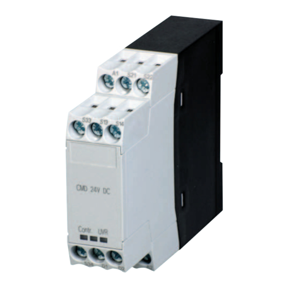
- Page 1 Moeller® series 10/12 MN04913001Z-EN Manual replaces 04/10 AWB2441-1595en Contactor monitoring device CMD(24VDC), CMDTD...
- Page 2 2010, edition date 04/10 edition 2010, edition date 10/12 See revision protocol in the “About this manual“ chapter © 2007 by Eaton Industries GmbH, 53105 Bonn Production: Heidrun Riege, René Wiegand Translation: Terence Osborn All rights reserved, including those of the translation.
- Page 3 Danger! Dangerous electrical voltage! Before commencing the installation • Disconnect the power supply of the device. • Suitable safety hardware and software measures should be implemented for the • Ensure that devices cannot be accidentally I/O interface so that a line or wire breakage restarted.
- Page 4 • Measures should be taken to ensure the • Wherever faults in the automation system proper restart of programs interrupted may cause damage to persons or property, after a voltage dip or failure. This should external measures must be implemented to not cause dangerous operating states even ensure a safe operating state in the event for a short time.
-
Page 5: Table Of Contents
10/12 MN04913001Z-EN Content About this Manual Target group Writing conventions Abbreviations and symbols List of revisions CMD contactor monitoring relays Application of the CMD System overview Improper use Engineering Distinction from other regulations Performance Level Control system of category 3 Average diagnostic coverage DC Mean time to dangerous failure MTTF Approvals... - Page 6 10/12 MN04913001Z-EN Content Appendix Nameplate Technical Data – General – Contacts – Magnet systems Dimensions...
-
Page 7: About This Manual
10/12 MN04913001Z-EN About this Manual Target group This manual is aimed at specialist personnel involved in the design, installation, commissioning and maintenance of plant safety functions. It describes the use of the CMD contactor monitoring device in safety-related control systems. Writing conventions Symbols used in this manual have the following meanings: Caution! -
Page 8: Abbreviations And Symbols
10/12 MN04913001Z-EN About this Manual Abbreviations and symbols Institute for Occupational Safety and Health (BGIA) Safety Integrated Level Performance Level Common cause failure Average diagnostic coverage MTTF Mean time to dangerous failure Lifespan up to a dangerous failure Mean number of annual switch operations List of revisions Edition page... -
Page 9: Cmd Contactor Monitoring Relays
10/12 MN04913001Z-EN CMD contactor monitoring relays Application of the CMD In the event of an emergency in safety-related electrical control circuits, the hazardous plant section is shut down from the main power supply by means of contactors a Emergency stop (stopping in the event of an emergency) in accordance with IEC/EN 60204-1. -
Page 10: System Overview
The CMD contactor monitoring device requires a control power supply. CMD(24VDC), CMDTD: control voltage 24 V DC The CMD relay can be combined with the following Eaton contactors, motor-protective circuit-breakers and circuit- breakers: • Contactors/contact modules, fitted with an auxiliary NC... -
Page 11: Improper Use
– NZM4, N4 + NZM4-XUV Improper use The CMD contactor monitoring device has only been tested and approved in combination with the Eaton contactors and circuit-breakers that are listed in section “System overview”, (a page 6). The CMD must therefore only be combined with these... - Page 12 10/12 MN04913001Z-EN...
-
Page 13: Engineering
10/12 MN04913001Z-EN Engineering Distinction from other The safety-related part of the CMD contactor monitoring regulations device's control system has EN/ISO 13849-1 approval. The CMD is used for safety-related applications in machine control systems. It has not been assigned to a SIL category as per IEC/EN 61508. -
Page 14: Average Diagnostic Coverage Dc Avg
10/12 MN04913001Z-EN Engineering Two CMD relays are required in reversing starter circuits. To attain category 3, faults were excluded by wiring inside a control cabinet. On disconnection via the undervoltage release, a time delay of 100 ms G20 % can occur. An enable circuit must be protected with a max. - Page 15 10/12 MN04913001Z-EN Mean time to dangerous failure MTTF The generally recognized inspection frequency is a hundred times more often than the MTTF . The test interval can be determined from: MTTF (formula 1) Test section “Mean time to dangerous failure MTTFd” (a page 11).
- Page 16 10/12 MN04913001Z-EN Engineering Table 1: values for contactors Contactor value Utilization category Utilization category Utilization category AC-3 AC-4 AC-1 [Mill. switch opera- [Mill. switch opera- [Mill. switch opera- tions] tions] tions] DILM7 DILM9 DILM12 DILM15 0.75 DILM17 DILM25 DILM32 DILM40 DILM50 DILM65 DILM72...
- Page 17 10/12 MN04913001Z-EN Mean time to dangerous failure MTTF The MTTF value of the undervoltage release depends on the application. The following values can be estimated for B Table 2: values for undervoltage release Undervoltage release value [Switch operations] NZM1 10000 NZM2 10000 NZM3...
-
Page 18: Approvals
10/12 MN04913001Z-EN Engineering Approvals The CMD contactor monitoring device is approved by the IFA in combination with Eaton contactors and circuit-breakers (a section ”System overview”, Page 6). A CE declaration of conformity and a prototype test certifica- tion are also available. -
Page 19: Installation
10/12 MN04913001Z-EN Installation Mounting The CMD contactor monitoring device is mounted on a top- hat rail. Any mounting position is possible. 90° 90° 90° 90° Figure 2: Mounting positions for CMD The electrical mounting space must at least meet the requirements of IP54 protection. -
Page 20: Connection For Dol Starters
L1 L2 L3 1.13 1.14 -Q11 I > I > I > T2 T3 -Q11 TEST -Q11 -Q11 S21 S22 S13 S14 S31 S32 W PE -Q11 U < ˜... -
Page 21: Connection For Reversing Starters
L1 L2 L3 1.13 1.14 -Q11 -Q12 I > I > I > T2 T3 -Q11 -Q12 TEST -Q11 -Q12 -Q11 -Q12 S21 S22 S13 S14 S31 S32 S21 S22 S13 S14 S31 S32 -Q12 -Q11 V W PE D1 D2 -Q11 -Q12 U <... -
Page 22: Wiring
10/12 MN04913001Z-EN Installation Wiring The following cables can be used for wiring at the terminals at the CMD contactor monitoring device. Table 4: Conductor cross-sections lb-In 1 x (0.5 - 2.5) 1 x (0.5 - 2.5) 20 - 14 0.8 - 1.2 7.0 - 10.6 2 x (0.5 - 1.5) 2 x (0.5 - 1.5) -
Page 23: Operating The Device
10/12 MN04913001Z-EN Operating the device Function messages The CMD contactor monitoring device is fitted with two internal LEDs for status indication at the device. Figure 5: LED indication a A green LED labelled „Contr.“ (Control) The „Contr.“ LED indicates the control for the CMD and the contactor. -
Page 24: Test Function
10/12 MN04913001Z-EN Operating the device Test function The control system must be tested regularly during operation via the Test button. An annual test is sufficient. The test determines the reliable operation of the undervoltage release. The test button must be provided with another NO contact in addition to the NC contact for the actual test. -
Page 25: Appendix
10/12 MN04913001Z-EN Appendix Nameplate 24V DC ® N4246 =100ms contactor weld A1-A2 S21-S22 off S13-S14 IFA0703007 D1-D2 Sicherheit geprüft tested safety S31-S22 S31-S14 EN 60947-5-1 Ue 24V DC Uimp 0.8kV Ui 100V Eaton Industries GmbH 53105 Bonn Germany Made in Germany... -
Page 26: Technical Data
10/12 MN04913001Z-EN Appendix Technical Data General Standards IEC/EN 60947; UL, CSA Lifespan, mechanical DC operated Operations x 10 Maximum operating Operations x 10 9000 frequency Climatic proofing • Damp heat, constant, to IEC 60068-2-78 • Damp heat, cyclic, to IEC 60068-2-30 Ambient air temperature Storage °C... -
Page 27: Contacts
10/12 MN04913001Z-EN Dimensions Standard screwdriver 0.8 x 5.5 / 1 x 6 max. tightening torque 1) Minimum clearance to adjacent devices: 22.5 mm Contacts Rated impulse withstand voltage V AC Overvoltage category/ III/3 pollution degree Rated insulation voltage V AC Rated operational voltage V DC Conventional thermal current...
Need help?
Do you have a question about the Moeller Series and is the answer not in the manual?
Questions and answers