Table of Contents
Advertisement
Quick Links
Advertisement
Table of Contents

Related Manuals for Commell Mini-ITX Motherboard LV-671


Summary of Contents for Commell Mini-ITX Motherboard LV-671
- Page 1 LV-671 Mini-ITX Motherboard User’s Manual Edition: 1.42 2007/11/19...
- Page 2 LV-671 User’s Manual...
- Page 3 LV-671 User’s Manual...
- Page 4 LV-671 User’s Manual Copyright © Copyright 2003 - 2004. All rights reserved. This document is copyrighted and all rights are reserved. The information in this document is subject to change without prior notice to make improvements to the products. This document contains proprietary information and protected by copyright. No part of this document may be reproduced, copied, or translated in any form or any means without prior written permission of the manufacturer.
-
Page 5: Packing List
LV-671 User’s Manual Packing List Please check the package before you use this product Hardware: LV-671 Mini-ITX motherboard x 1 Cable Kit: 40-pin ATA100 IDE Cable x 1 26-pin Slim Type Floppy Cable x 1 4-pin to 4-pin Power Cable x 1 CPU Cooler x 1 Other Accessories Driver CD (Including User’s Manual ) x 1... - Page 6 LV-671 User’s Manual Chapter 1 <Introduction> ... 9 <Product Overview>... 9 1.2 <Product Specification> ... 10 1.3 <Component Placement> ... 13 1.4 <Block Diagram>... 14 Chapter 2 <Hardware Setup>... 15 2.1 <Connector Location>... 15 2.2 <Jumper Reference> ... 16 2.3 <Connector Reference>... 17 2.3.1 <Internal Connector>...
- Page 7 LV-671 User’s Manual Chapter 3 <System Setup> ... 37 3.1 <Watchdog Timer Setting>... 37 3.2 <Audio Setting>... 38 3.3 <Display Device Setup>... 39 Chapter 4 <BIOS Setup> ... 43 Appendix A <I/O Port Pin Assignment>... 45 A.1 <IDE Port> ... 45 A.2 <Floppy Port>...
- Page 8 LV-671 User’s Manual (This Page is Left for Blank)
-
Page 9: Chapter 1
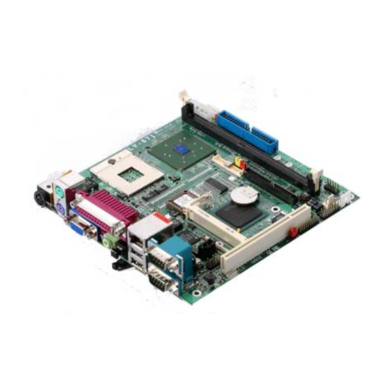
LV-671 User’s Manual Chapter 1 <Introduction> 1.1 <Product Overview> LV-671 is an all-in-one industrial compact Pentium-M level motherboard based on Mini-ITX form factor at 170 x 170 mm of dimension. Based on Intel 855GME and ICH4 chipset, LV-671 offers the compact, embedded, value and high performance solution with Intel Pentium-M CPU, 400MHz/533MHz of FSB, 1GBytes DDR200/266/333 SDRAM with ECC, Intel 855GME GMCH built-in Intel Extreme Graphics 2, Intel PRO/1000+ LAN, Hi-Speed USB 2.0, 5.1 channel and S/P DIF 3D audio, 18/24-bit dual channel LVDS, GPIO and... -
Page 10: Product Specification
LV-671 User’s Manual 1.2 <Product Specification> General Specification Form Factor Mini-ITX motherboard at 170 x 170 mm (L x W) Package: 478 pin PGA/ 479 pin BGA L2 Cache: 512KB/1MB/2MB FSB: 400MHz/533MHz ( The Intel® Celeron® M Processor 4xx series have been designed to work with the Mobile Intel®... - Page 11 External SPDIF connector on rear panel Internal 10-pin header for line-in/-out, MIC-out, 4-pin header for CD-in Solid State Disk Interface Flash Type Compact Flash Type-I for Compact Flash Card or IBM Micro Drive Capacity Up to 1GB flash memory Expansion Interface Slim PCI Slot...
- Page 12 LV-671 User’s Manual Power and Environment Power One external 19V/12V (auto switching) DC Adapter connector on Requirement rear panel 4-pin onboard 12V P4 4-pin power connector (Two power resources selectable for each) Input Voltage 11V ~ 13V for 12V power supply Range 16V ~ 20V for 19V power supply Input Current...
-
Page 13: Component Placement
LV-671 User’s Manual 1.3 <Component Placement> 1 x 184-pin DDR266/333 DIMM up to 1GB Intel ICH4 (Southbridge) Intel 855GME (Northbridge) Socket479 For 478-pin PGA Pentium M/Celeron M Onboard DC to DC inverter Intel 82540EM Gigabit LAN Onboard 479-pin BGA Pentium M/Celeron M Component Placement Introduction REALTEK... -
Page 14: Block Diagram
LV-671 User’s Manual 1.4 <Block Diagram> Intel Pentium M processor with FC-PGA2/FC-BGA2 LVDS LVDS AGP 4x Mini-AGP DVO B/C UltraATA100 ATAPI Devices USB Devices 480Mb/s Audio AC97 Codec IrDA PS/2 COM Port Parallel Port Floppy 400MHz/533MHz FSB 855GME USB2.0 ICH4 Compact Flash 1 x 184-pin DDR266/333... -
Page 15: Chapter 2
LV-671 User’s Manual Chapter 2 <Hardware Setup> This chapter contains the information for installation of hardware. The install procedure includes jumper settings, CPU and memory installation, fan, I/O and panel connections. 2.1 <Connector Location> CN_BPWR CN_INV DIMM MINI_AGP MINIPCI CN_IR CPUFAN CN 12V DC_IN... -
Page 16: Jumper Reference
LV-671 User’s Manual 2.2 <Jumper Reference> Jumper Function JRTC COMS Operate / Clear Setting JLAN LAN1 Enable/Disable JVLCD LCD Panel Voltage Setting JCFSEL Compact Flash Address Setting JDOM IDE1 5V Voltage Enable/Disable JDOM JCFSEL JVLCD Hardware Setup JRTC JLAN Jumper Reference... -
Page 17: External I/O Connector
LV-671 User’s Manual 2.3 <Connector Reference> 2.3.1 <Internal Connector> Connector Function DIMM IDE1 IDE2 CN_USB1 CN_USB2 CN_IR CN_12V CN_BPWR CN_SPWR JFRNT CPUFAN SYSFAN CN_AUDIO CDIN CN_WOL CN_LVDS CN_INV CN_DIO CN_LAN2 CN_2ND_IO PCMCIA 2.3.2 <External I/O connector> Connector Function DC_IN Printer SPEAKER SPDIF DUAL_USB... -
Page 18: Cpu Installation
LV-671 User’s Manual 2.4 <System Setup> 2.4.1 <CPU Installation> The board supports Intel Pentium M/ Celeron M processor with 400MHz/533MHz of front side bus, 512KB/1MB/2MB of L2 cache, there are two package type of the processor, 478-pin PGA for socket479 onboard version; 479-pin BGA for embedded processor version. Please check installation steps below for onboard socket479 version. -
Page 19: Memory Installation
LV-671 User’s Manual 2.4.2 <Memory Installation> The board supports one 184-pin DDR266/333 (PC2100/PC2700) SDRAM up to 1GB of capacity, and supports ECC (Error Correcting Code), unbufferred memory modules. Please check the pin number to match the socket side well before installing memory module. Memory Installation 104-pin 80-pin... -
Page 20: Cpu Cooler Installation
LV-671 User’s Manual 2.4.3 <CPU Cooler Installation> The board accessories come with one CPU cooler, the cooler’s specification is listed below, please check the installation steps before you start. Notice: Installing the cooler improperly may cause the system unstable, if you face system rebooting or other issue, please check this point. -
Page 21: Cmos Setup
LV-671 User’s Manual 2.5 <CMOS Setup> The board’s data of CMOS can be setting in BIOS. If the board refuses to boot due to inappropriate CMOS settings, here is how to proceed to clear (reset) the CMOS to its default values. Jumper: JRTC Type: Onboard 3-pin Header JRTC... -
Page 22: Ide Interface
LV-671 User’s Manual 2.6 <IDE Interface> The board supports two IDE interface up to 4 ATAPI devices, base on Intel ICH4, the IDE interface supports ATA66/100 ATAPI drives. The IDE1 supports +5V on pin-20 for DOM (Disk on Module), the jumper JDOM can let you select enable/disable this support. Jumper: JDOM Type: onboard 3-pin header JDOM... -
Page 23: Compact Flash Interface
LV-671 User’s Manual 2.7 Compact Flash Interface The board supports Compact Flash Type I socket for storage flash disk only, the jumper JCFSEL can let you to setup the flash card operate on secondary master or slave mode. Jumper: JCFSEL Type: onboard 3-pin header JCFSEL Mode... -
Page 24: Digital Display Interface
LV-671 User’s Manual Hardware Setup 2.8 <Display Interface> 2.8.1 <Analog display interface> The board is integrated with Intel 855GM GMCH chipset built-in Intel Extreme Graphics 2 with 266 MHz VGA core, 256-bit 3D engine and Intel Dynamic Video Memory up to 64MBytes shared with system memory. The CRT / analog VGA interface includes one external DB15 female connector on bracket on board. - Page 25 LV-671 User’s Manual Connector: CN_INV Type: 5-pin LVDS Power Header Description +12V ENABKL Connector: CN_LVDS Type: onboard 40-pin connector for LVDS connector Connector model: HIROSE DF13-40DP-1.25V To setup the LCD, you need the components below: A panel (support up to 24-bit dual channel) with LVDS interfaces. An inverter for panel’s backlight power.
- Page 26 LV-671 User’s Manual LCD installing guide: Prepare a panel, inverter and LV-671. Please check the datasheet of the panel to see the voltage of the panel, and set the jumper JVLCD to +5V or +3.3V. Prepare a LVDS type LCD cable Panel side Connect all the devices well.
- Page 27 LV-671 User’s Manual After setup the devices well, you need to select the LCD panel type in the BIOS. The panel type mapping is list below: BIOS panel type selection form For 18-bit color Output format 640 x 480 800 x 600 1024 x 768 1280 x 1024 1400 x 1050 Dual Channel @ 108Mhz 13...
-
Page 28: Audio Interface
LV-671 User’s Manual 2.9 <Audio Interface> The board integrates Intel ICH4 with REALTEK ALC655 codec for AC97 Rev 2.3; it comes with the features below: ● Microsoft WHQL/WLP 2.0 audio compliance ● Software selectable for 2-channel/5.1-channel sound ● 16-bit Stereo full-duplex CODEC with 48KHz sampling rate ●... - Page 29 LV-671 User’s Manual Connector: CN_AUDIO Type: 10-pin (2 x 5) 2.54-pitch header Description Line – Right Line – Left Line Out – Right Connector: CDIN Type: 4-pin header Description CD – Left Ground Ground CD – Right Audio Interface Description Ground Ground Line Out –...
-
Page 30: Ethernet Interface
LV-671 User’s Manual 2.10 <Ethernet Interface> The board integrates 10Base-T/100Base-TX/1000Base-T auto-switching Ethernet with full duplex and IEEE 802.3U compliant. The LAN function comes with a RJ45 jack on the rear I/O panel. The CN_WOL is for the Wake-Up-On-LAN function link with PCI LAN Card. Connector: CN_WOL Type: onboard 3-pin (1 x 3) wafer connector Description... -
Page 31: Power And Fan Connector
LV-671 User’s Manual 2.11 <Power and Fan connector> The board comes with a 4-pin Mini-DIN power connector for DC 12V/19V auto-switching input, it also has one 4-pin P4 additional use power connector for internal power supply, you can choose one pf them to meet your application. The board has two power connectors for 5V/12V output to powering your ATAPI drives directly, and it has two fan connectors for CPU and system cooling. - Page 32 LV-671 User’s Manual Connector: CN_12V Type: 4-pin standard Pentium 4 +12V power connector Description +12V Ground Connector: DC_IN Type: 4-pin DC power connector Description +12V +12V Connector: CPUFAN, SYSFAN Type: 3-pin fan wafer connector Pin Description Ground Connector: CN_BPWR Type: 4-pin P-type connector for +5V/+12V Description Note: Maximum output voltage: 12V/5A &...
-
Page 33: Gpio Interface
LV-671 User’s Manual 2.12 <GPIO Interface> The board offers 16-bit digital I/O to customize its configuration to your control needs. For example, you may configure the digital I/O to control the opening and closing of the cash drawer or to sense the warning signal from a tripped UPS. Connector: CN_DIO Type: 20-pin (10 x 2) header Description... -
Page 34: Expansive Interface
LV-671 User’s Manual Hardware Setup 2.13 <Expansive Interface> The board comes with one slim type PCI slot and one optional Mini-AGP or Mini-PCI interface. The slim PCI slot supports up to 2 PCI devices through an optional riser card. For Mini-PCI interface, you can obtain a wireless LAN card for potable system. -
Page 35: Switch And Indicator
LV-671 User’s Manual 2.14 <Switch and Indicator> Connector: JFRNT Type: onboard 14-pin (2 x 7) 2.54-pitch header Function IDE LED Reset Power Button Switch and Indicator Signal Vcc (+) Active Reset PWRBT 5VSB Hardware Setup Signal Function (+) Vcc Power Speaker SPKIN JFRNT... - Page 36 LV-671 User’s Manual (This Page is Left for Blank)
-
Page 37: Watchdog Timer Setting
LV-671 User’s Manual Chapter 3 <System Setup> 3.1 <Watchdog Timer Setting> The watchdog timer makes the system auto-reset while it stops to work for a period. The integrated watchdog timer can be setup as system reset mode by program. Timeout Value Range - 1 to 255 - Second or Minute Program Sample... -
Page 38: Audio Setting
LV-671 User’s Manual 3.2 <Audio Setting> The board integrates Intel® ICH4 with REALTEK® ALC655 codec. It can support 2-channel or 5.1 channel sound under system configuration. Please follow the steps below to setup your sound system. Install REALTEK AC97 Audio driver. Lunch the control panel and Sound Effect Manager. -
Page 39: Display Device Setup
LV-671 User’s Manual System Setup 3.3 <Display Device Setup> This chapter shows you how to setup the display device under Windows OS. Before you using your display device: 1. Check your software Before you can use the display device properly, please install the VGA driver. 2. - Page 40 LV-671 User’s Manual System Setup For advanced display settings, please click Advanced… button and choose Intel(R) Extreme Graphics. Please click Graphics Properties button to enter the advanced setup. Display Device Setup...
- Page 41 LV-671 User’s Manual While you entering the Graphics Properties, you will see the options below: Display Device Setup System Setup This option can let you configure the CRT monitors for Colors, Screen Area (Resolution) and Refresh Rate. This option can let you configure the LCD panel for Colors, Screen Area (Resolution) and Full Screen option.
- Page 42 LV-671 User’s Manual System Setup This option can let you configure the Dual Display for clone mode (same display on two devices) This option can let you configure the Dual Display for Extended Desktop mode Display Device Setup...
-
Page 43: Chapter 4
The single board computer uses the Award BIOS for the system configuration. The Award BIOS in the single board computer is a customized version of the industrial standard BIOS for IBM PC AT-compatible computers. It supports Intel x86 and compatible CPU architecture based processors and computers. The BIOS provides critical low-level support for the system central processing, memory and I/O sub-systems. - Page 44 LV-671 User’s Manual (This Page is Left for Blank)
-
Page 45: Appendix A
LV-671 User’s Manual Appendix A <I/O Port Pin Assignment> A.1 <IDE Port> Connector: IDE1 Type: 40-pin (20 x 2) box header Description Reset Ground IOW-/STOP IOR-/HDMARDY IORDY/DDMARDY DACK- CS1 (MASTER CS) LED ACT- IDE Port I/O Port Pin Assignment Description Ground VCC (JDOM) Ground... - Page 46 LV-671 User’s Manual Connector: IDE2 Type: 44-pin (22 x 2) box header Description Reset Ground IOW-/STOP IOR-/HDMARDY IORDY/DDMARDY DACK- IDEACT- Ground I/O Port Pin Assignment Description Ground Ground Ground Ground IDESEL Ground CBLID Ground Ground IDE Port...
-
Page 47: A.3 < Usb Interface
LV-671 User’s Manual A.2 <Floppy Port> Connector: FDD Type: 26-pin connector Description DRV1 MTR1 Ground Ground Ground Ground A.3 < USB Interface > Connector: CN_USB1, CN_USB2 Type: 10-pin (5 x 2) header for dual USB Ports Description Data0- Data0+ Ground PS. -
Page 48: A.4
LV-671 User’s Manual A.4 <IrDA Port> Connector: CN_IR Type: 5-pin header for SIR Ports Description IRRX Ground IRTX A.5 < VGA Port > Connector: VGA Type: 15-pin D-sub female connector on bracket Description GREEN BLUE Ground A.6 < LAN Port > Connector: RJ45 Type: RJ45 connector with LED on bracket Description... -
Page 49: A.7 < Serial Port
LV-671 User’s Manual A.7 < Serial Port > Connector: COM1 Type: 9-pin D-sub male connector on bracket Description MDCD1- MSIN1- MSO1- MDTR1- Ground Connector: COM2 Type: 9-pin D-sub male connector on bracket Description MDCD2- MSIN2- MSO2- MDTR2- Ground Output Voltage: +/- 9V. Serial Port I/O Port Pin Assignment Description... - Page 50 LV-671 User’s Manual (This Page is Left for Blank)
-
Page 51: B.2
LV-671 User’s Manual Appendix B <Flash BIOS> B.1 <Flash Tool> The board is based on Award BIOS and can be updated easily by the BIOS auto flash tool. You can download the tool online at the address below: http://www.phoenix.com/en/home/ http://www.commell.com.tw/Support/Support_SBC.htm File name of the tool is “awdflash.exe”, it’s the utility that can write the data into the BIOS flash ship and update the BIOS. - Page 52 LV-671 User’s Manual (This Page is Left for Blank)
-
Page 53: Appendix C
LV-671 User’s Manual Appendix C <System Resource> C.1 <I/O Address Map> Address Range x0000 - x000F x0010 - x001F x0020 - x0021 x0022 - x003F x0040 - x0043 x0044 - x005F x0060 - x0060 x0061 - x0061 x0062 - x0063 x0064 - x0064 x0065 - x006F x0070 - x0073... - Page 54 LV-671 User’s Manual x03F8 - x03FF x0400 - x04BF x04D0 - x04D1 x0500 - x051F x0778 - x077B x0A78 - x0A7B x0B78 - x0B7B x0BBC - x0BBF x0CF8 - x0CFF x0E78 - x0E7B x0F78 - x0F7B x0FBC - x0FBF xA000 - xBFFF xB000 - xB03F xC000 - xC01F xC400 - xC41F...
-
Page 55: C.2
LV-671 User’s Manual C.2 <Memory Address Map> Range x00000000 - x0009FFFF x000A0000 - x000AFFFF x000B0000 - x000BFFFF x000C0000 - x000CC7FF x000CC800 - x000CFFFF x000E0000 - x000EFFFF x000F0000 - x000F7FFF x000F8000 - x000FBFFF x000FC000 - x000FFFFF x00100000 - x1DFEFFFF x1DFF0000 - x1DFFFFFF xD0000000 - xD7FFFFFF xD8000000 - xDFFFFFFF xE0000000 - xE0000FFF... -
Page 56: C.3
LV-671 User’s Manual C.3 <System IRQ and DMA Resource> C3.1 IRQ IRQ Number System Clock Standard 101/102-Key or Microsoft Natural Keyboard Programmable Interrupt Controller Communication Port (COM2) Communication Port (COM1) Realtek AC'97 Audio Intel(R) 82801DB/DBM SMBus Controller - 24C3 ACPI IRQ Holder for PCI IRQ Steering Standard Floppy Controller Printer Port (LPT1) System CMOS/ Real Time Clock... - Page 57 LV-671 User’s Manual C3.2 DMA Channel Device (free) (free) Standard Floppy Disk Controller (free) Direct Memory Access Controller (free) (free) (free) System IRQ and DMA Resource System Resource...
-
Page 58: Contact Information
LV-671 User’s Manual Contact Information Any advice or comment about our products and service, or anything we can help you please don’t hesitate to contact with us. We will do our best to support you for your products, projects and business Taiwan Commate Computer Inc.
Need help?
Do you have a question about the Mini-ITX Motherboard LV-671 and is the answer not in the manual?
Questions and answers