Table of Contents
Advertisement
Quick Links
Advertisement
Table of Contents

Related Manuals for Commell LV-67T


Summary of Contents for Commell LV-67T
- Page 1 LV-67T Mini-ITX Motherboard User’s Manual Edition 1.0 2016/08/11...
- Page 2 LV-67T User’s Manual Copyright Copyright 2016, all rights reserved. This document is copyrighted and all rights are reserved. The information in this document is subject to change without prior notice to make improvements to the products. This document contains proprietary information and protected by copyright. No part of this document may be reproduced, copied, or translated in any form or any means without prior written permission of the manufacturer.
-
Page 3: Packing List
LV-67T User’s Manual Packing List: Please check the package content before you starting using the board. 1 x LV-67T Mini-ITX Motherboard (include Cooler Fan) 2 x SATA Cable (OALSATA3-L / 1040529) 1 x Power Cable 1 x DC Power Cable... - Page 4 LV-67T User’s Manual Index Chapter 1 <Introduction>............... 4 1.1 <Product Overview> ................. 4 1.2 <Product Specification> ................5 1.3 <Mechanical Drawing> ................6 1.4 <Block Diagram> ..................9 Chapter 2 <Hardware setup> ............10 2.1 <Connector Location and Reference> ........... 10 2.1.1 <Internal connectors list>...
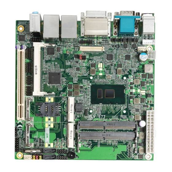
- Page 5 1.1 <Product Overview> Generation Intel® Core™ U-series i7, i5, LV-67T is Mini-ITX Motherboard which supports 6 i3, Celeron Mobile Processor with Sunrise Point PCH-LP, integrated HD Graphics, DDR4 memory, Realtek High Definition Audio, Intel Gigabit LAN, Serial ATA3 with AHCI function for a system.
-
Page 6: Product Specification
LV-67T User’s Manual 1.2 <Product Specification> System Intel® Skylake Core™ i7, i5, i3, Celeron U-series Processor Processor FCBGA1356 with MCP Chipset Sunrise Point-LP 2 x DDR4 SO-DIMM 1866/2133 MHz up to 32GB Memory Support Non-ECC memory Watchdog Timer Generates a system reset with internal timer for 1min/s ~ 255min/s... -
Page 7: Mechanical Drawing
LV-67T User’s Manual 1.3 <Mechanical Drawing> Positive... - Page 8 LV-67T User’s Manual...
-
Page 9: Block Diagram
LV-67T User’s Manual 1.4 <Block Diagram> eDP1 DDR4 PTN3460 Channel A SO-DIMM 1 x LVDS DDR4 Channel B DDI2 Gen Processor SO-DIMM 1 x DVI-I PCIe x1 I219-LM PCIe x1 I210-AT DDI3 1 x DisplayPort PCIe x1 MiniCard1 IC 3355... -
Page 10: Chapter 2
LV-67T User’s Manual Chapter 2 <Hardware setup> 2.1 <Connector Location and Reference> CN_AUDIO CN_INV CPUFAN CN_COM5/6 CN_CRT CN_LVDS DC_IN CN_COM3/4 MINIPCI CN_DIO CN_LPC MINI_CARD1 SIMM CN_SMBUS MINI_CARD2 SATA3-2 JFRNT SYSFAN SATA3-2 CN_USB2 SO-DIMM2 CN_USB1 SATA3-1 SO-DIMM1 COM2 DVI-I LAN1 LAN2... -
Page 11: Internal Connectors List
LV-67T User’s Manual 2.1.1 <Internal connectors list> Connector Function SO-DIMM1/2 260-pin DDR4 SO-DIMM slot SATA3-1/2 10-pin Serial ATA3 connector CN_AUDIO 5 x 2-pin audio pin header CN_LPC 6 x 2-pin LPC pin header 6 x 2-pin General Purpose In/Out pin header... -
Page 12: Jumper Location And Reference
LV-67T User’s Manual 2.2 <Jumper Location and Reference> JVLCD JP2 JP1 JCSEL2 JCSEL1 JMSATA JRTC 2.2.1 <Jumper list> Jumper Function Power mode select JRTC CMOS Normal/Clear Setting JVLCD Panel Voltage Setting JMSATA MiniCard2 mSATA Setting JCSEL1/2 COM2 RS232/422/485 select JP1/2 COM1 and COM2 9-pin setting 2.2.2 <Clear CMOS and Power on type selection>... -
Page 13: Installing The Memory
LV-67T User’s Manual 2.3 <Installing the Memory> In the process, the board must be powered off. 1. Put the memory tilt into the slot. Note the Memory notch key aligned slot key. 2. Then press down till lock into the mounting notch. -
Page 14: I/O Interface
LV-67T User’s Manual 2.4 <I/O interface> 2.4.1 <Serial ATA interface> Support RAID0 and 1. SATA3-2 SATA3-1 2.4.2 <Ethernet interface> The board provide I210-AT and I219-LM Gigabit Ethernet which supports WOL on rear I/O. It supports Intel® AMT 11.0 feature on I219-LM. -
Page 15: Display Interface
LV-67T User’s Manual 2.4.3 <Display interface> Based on the 6th Gen CPU with built-in HD Graphics, the DisplayPort resolution up to 3840x2160 @ 60Hz or 4096x2304 @ 60Hz, the HDMI up to 4096x2304 @ 24Hz and LVDS up to 1920x1200 @ 60Hz support 18/24-bit color depth and dual channel. - Page 16 LV-67T User’s Manual CN_LVDS: LVDS 40-pin connector ( Model: HIROSE DF13-40DP-1.25V compatible Signal Signal Set by JVLCD Set by JVLCD Detect (Active low) A_LVDS_0- B_LVDS_0- A_LVDS_0+ B_LVDS_0+ A_LVDS_1- B_LVDS_1- A_LVDS_1+ B_LVDS_1+ A_LVDS_2- B_LVDS_2- A_LVDS_2+ B_LVDS_2+ A_LVDS_CLK- B_LVDS_3- A_LVDS_CLK+ B_LVDS_3+ A_LVDS_3-...
-
Page 17: Serial Port Interface
LV-67T User’s Manual 2.4.4 <Serial Port interface> CN_COM5/6 JCSEL2 CN_COM3/4 JCSEL1 COM2 COM1 COM1: RS232 DB9 connector Signal Signal Set by JP2 COM2: RS232/422/485 DB9 connector Signal Signal DCD/ 422TX-/ 485- RXD/ 422TX+/ 485+ TXD/ 422RX+ DTR/ 422RX- Set by JP1... - Page 18 LV-67T User’s Manual COM3/4,5/6: RS232 20-pin header (Pitch 1.27mm x 2.54mm) Signal Signal DCD1 RXD1 TXD1 DTR1 DSR1 RTS1 CTS1 DCD2 RXD2 TXD2 DTR2 DSR2 RTS2 CTS2 JP1, JP2: COM1, COM2 pin-9 setting Jumper settings Function RI (Default) Effective patterns of connection: 1-2 / 3-4 / 5-6...
-
Page 19: Usb Interface
LV-67T User’s Manual 2.4.5 <USB interface> USB2 CN_USB2 CN_USB1 USB3.0-1 (5VSB) USB3.0-2 (5VSB) USB1 & 2 are USB3.0 interface. CN_USB1/2: Front panel USB2.0 10-pin header (Pitch 2.54mm) Signal Signal 5VSB 5VSB DATA0- DATA1- DATA0+ DATA1+ 2.4.6 <Audio interface> Rear Audio Jack... -
Page 20: Expansion Slot
LV-67T User’s Manual CN_AUDIO: Front panel audio 10-pin header (Pitch 2.54mm) Signal Signal MIC_L MIC_R FP_OUT_R MIC_DETECT SENSE FP_OUT_L FP_OUT_DETECT 2.4.7 <Expansion slot> MINIPCI SIMM MINI_CARD1 JMSATA MINI_CARD2 MINI_CARD1 and MINI_CARD2 have special design to compatible our MiniPCIe card (ex: MPX-574D2, MPX-210D2 etc) and MINI_CARD2 supports mSATA set by JMSATA. -
Page 21: Front Panel Switch And Indicator
LV-67T User’s Manual <SIM> This is for 3G miniPCIe card which doesn’t have SIM slot. Slide the direction of the arrow open the cover. Then press down and slide the Insert the SIM card and make direction of the arrow close the cover. -
Page 22: Other Interface
LV-67T User’s Manual JFRNT: Front panel switch and indicator 14-pin header (Pitch 2.54mm) Signal Signal HDD_LED+ Power_LED+ HDD_LED- Reset+ Power_LED- Reset- Speaker+ Power_ON+ Power_ON- Speaker- 2.4.9 <Other interface> CN_DIO CN_LPC CPUFAN SMBUS SYSFAN When using GPIO function, please note: As Output: Open-drain, most applications need use an external pull up resistor. - Page 23 LV-67T User’s Manual CN_DIO: GPIO 12-pin header (Pitch 2.00mm) Signal Signal GPIO0 GPIO4 GPIO1 GPIO5 GPIO2 GPIO6 GPIO3 GPIO7 CN_LPC: LPC 12-pin header (Pitch 2.00mm) Signal Signal -LFRAME LAD3 LAD2 LAD1 LAD0 3.3V SERIRQ 3.3VSB Note: Support TPM module. SMBUS: SMBus 5-pin connector...
-
Page 24: Power Supply
LV-67T User’s Manual 2.5 <Power supply> 2.5.1 <Power input> DC_IN The DC_IN support 9~24V wide voltage input. Note that the DC_IN and ATX do not use at the same time, it will certainly cause damage. DC_IN: ATX12V 4-pin connector Signal... -
Page 25: Power Output
LV-67T User’s Manual 2.5.2 <Power output> It is supply to the HDD, CD-ROM or other device. If using DC_IN as input, that ATX will as output. ATX: main power 24-pin connector (As output) Signal Signal 3.3V 3.3V 3.3V 3.3V Note that Maximum output power: 12V/2A, 5V/3A, 3.3V/3A... -
Page 26: Appendix A
LV-67T User’s Manual Appendix A <Flash BIOS> A.1 <Flash tool> The board is based on Phoenix BIOS and can be updated easily by the BIOS auto flash tool. You can download the tool online at the address below: LV-67T reflash tool The tool’s file name is “fpt.exe”, it’s the utility that can write the data into the... -
Page 27: Appendix B
LV-67T User’s Manual Appendix B <Win7 Installation Notes> B.1 <ME driver> Before installing, it need to install Microsoft Hotfix KB2685611 first for Win7 32/64 bit. More information please refer https://www.microsoft.com/en-us/download/details.aspx?id=38423 B.2 <USB3.0 driver> The Skylake platform removed EHCI host controller, therefore, before install new Win7 OS, need to embed the USB3.0 driver to Win7 installation image... -
Page 28: Appendix C
LV-67T User’s Manual Appendix C <LCD Panel Type select> According your panel, it need to select the correct resolution in the BIOS. If there is no fit your panel type, please feedback for us to make OEM modol. BIOS panel type selection form (BIOS Version:1.0) -
Page 29: Appendix D
LV-67T User’s Manual Appendix D <Programmable GPIO > The GPIO’ can be programmed with the MS-DOS debug program using simple IN/OUT commands. The DC characteristics please refer to GPIO paragraph (Page20). GPIO -o 4E 87 ;enter configuration -o 4E 87... -
Page 30: Appendix E
LV-67T User’s Manual Appendix E <Programmable Watch Dog Timer> Timeout value range 1 to 255 Minute and Second Program sample Watchdog timer setup as system reset with 5 second of timeout -o 4E 87 ;enter configuration -o 4E 87 -o 4E 07 -o 4F 08 ;select Logical Device... -
Page 31: Appendix F
LV-67T User’s Manual Appendix F <SATA RAID function setting> When use RAID function, it need to enter the BIOS set RAID mode first. [Advanced] > [Intel Advanced Menu] > [PCH-IO Configuration] > [SATA Configuration] > [SATA Mode Selection] > [RAID] At boot time, press <CTRL + I>... -
Page 32: Contact Information
Taiwan Commate computer Inc. 19F., NO.94, Sec. 1, Xintai 5 Rd., Xizhi Dist., New Taipei Address City 22102, Taiwan. +886-2-26963909 +886-2-26963911 Website www.commell.com.tw info@commell.com.tw (General infomation) E-mail tech@commell.com.tw (Technical Support) Commell is a brand name of Taiwan Commate computer Inc. -31-...
Need help?
Do you have a question about the LV-67T and is the answer not in the manual?
Questions and answers