Table of Contents
Advertisement
Quick Links
Quick Guide
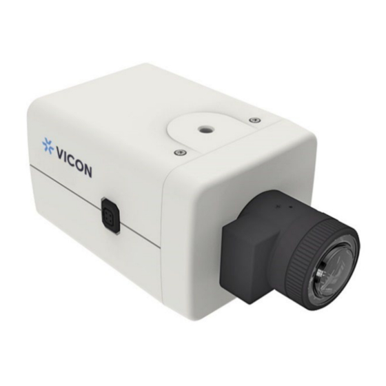
Roughneck Pro License Plate Recognition Box Camera
V2008-WNL-LPR Box Camera and
V2008-W1250-LPR Box Camera and Housing
XX324-30-01
Cybersecurity Notification:
accessing the device. To that end, these network cameras do not have a default password. A user defined
password with minimum password strength requirements must be set to access the device. See page 16 of
this Quick Guide for set-up instructions.
Vicon Industries Inc. does not warrant that the functions contained in this equipment will
meet your requirements or that the operation will be entirely error free or perform precisely as
described in the documentation. This system has not been designed to be used in
life-critical situations and must not be used for this purpose.
Document Number: 8009-8324-30-01 Product specifications subject to change without notice.
Issued: 10/2022 Copyright © 2022 Vicon Industries Inc. All rights reserved.
All network connected devices should use best practices for
Vicon Industries Inc.
Tel: 631-952-2288) Fax: 631-951-2288
Toll Free: 800-645-9116
24-Hour Technical Support: 800-34-VICON
UK: 44/(0) 1489-566300
www.vicon-security.com
(800-348-4266)
Advertisement
Table of Contents

Related Manuals for Vicon V2008-WNL-LPR


Summary of Contents for Vicon V2008-WNL-LPR
- Page 1 See page 16 of this Quick Guide for set-up instructions. Vicon Industries Inc. does not warrant that the functions contained in this equipment will Vicon Industries Inc.
-
Page 2: Table Of Contents
V2008-WNL-LPR/V2008-W1250-LPR Quick Guide Table of Content Product Overview Camera Physical Characteristics Housing Physical Characteristics Installation and Connection Package Contents Installation 2.2.1 Checking Appearance 2.2.2 LPR Installation Guidelines 2.2.3 Installing the Lens 2.2.4 Install the SD Card 2.2.5 Mounting the Camera in the HPOE-100 Housing 2.2.6... - Page 3 V2008-WNL-LPR/V2008-W1250-LPR Quick Guide WARNING This camera operates at 12 VDC/24 VAC/PoE (IEEE 802.3af Class 3). Installation and service should be performed only by qualified and experienced technicians and comply with all local codes and rules to maintain your warranty.
- Page 4 V2008-WNL-LPR/V2008-W1250-LPR Quick Guide FCC Compliance Statement Information to the user: This unit has been tested and found to comply with the limits for a Class B digital device pursuant to Part 15 of the FCC Rules. Operation is subject to the following two conditions: (1) this device may not cause harmful interference, and (2) this device must accept any interference received, including interference that may cause undesired operation.
-
Page 5: Product Overview
1 Product Overview 1.1 Camera Physical Characteristics The V2008-WNL-LPR box camera requires a customer-supplied lens and environmental housing. Follow the instructions provided with the lens and housing for installation of the camera. The V2008-W1250-LPR is supplied with the V12-50VF-P lens and the HPOE-100 camera housing. Both models include an SD card. - Page 6 V2008-WNL-LPR/V2008-W1250-LPR Quick Guide Name Description Lens (V12-50VF-P supplied with V2008-W1250-LPR) is attachable to the Lens camera’s lens mounting ring. Both top and bottom of the camera housing have one mount screw hole (1/4”-20) for mounting the camera. With V2008-W1250-LPR, use...
-
Page 7: Housing Physical Characteristics
V2008-WNL-LPR/V2008-W1250-LPR Quick Guide 1.2 Housing Physical Characteristics The V2008-WNL-LPR can be installed in the HPOE-100 camera housing; this is included with the V2008-W1250-LPR. Mounting Configuration and Dimensions: Housing Components: IR Cut (day/night) signal lines Housing Power Consumption: D-Fog Heater Always On (9 W) Heater 59°F/15°C On, 77°F/25°C Off (10 W) -
Page 8: Installation And Connection
V2008-WNL-LPR/V2008-W1250-LPR Quick Guide 2 Installation and Connection Package Contents Check if all items listed below are included in the packing box. Box Camera * 1 V12-50VF-P Lens * 1 (if V2008-W1250-LPR is purchased) Terminal Block * 1 SD Card * 1 HPOE-100 Camera Housing * 1 (if V2008-W1250-LPR is purchased);... - Page 9 720p image with a horizontal Pixels per Foot (PPF)=80. Refer to the Vicon LPR Camera Setup and Integration Guide for details on setting up the proper field-of-view (FOV). On the Live screen on the camera interface, the Calibration pattern can be enabled; calibration lines are shown at 20 pixels.
-
Page 10: Installing The Lens
V2008-WNL-LPR/V2008-W1250-LPR Quick Guide 2.2.3 Installing the Lens Attach the supplied V12-50VF-P lens (if V2008-W1250-LPR is purchased) or the customer-supplied lens onto the camera’s lens mounting ring. Screw the lens onto the lens mount. Be careful to prevent dust from entering the space between the lens and the imager. If necessary, use clean, compressed air to remove any foreign matter (refer to the instructions for the lens as needed). -
Page 11: Mounting The Camera In The Hpoe-100 Housing
V2008-WNL-LPR/V2008-W1250-LPR Quick Guide 2.2.5 Mounting the Camera in the HPOE-100 Housing Installation Recommendation: If the camera housing is to be installed in a tropical, sea coastal, or an environment where salt water or corrosive industrial waste-water/moisture are present, be sure to seal each stainless steel screw and fitting with a silicon grease compound. - Page 12 V2008-WNL-LPR/V2008-W1250-LPR Quick Guide Locate the white and green wires that are on the small day/night PC board mounted in the housing. The I/O interfaces are on the rear panel of the box camera. The white wire connects from RLY-1 on PCB to AI (Alarm In) on the camera and the green wire connects from RLY-2 on PCB to GND on the camera (ground;...
- Page 13 V2008-WNL-LPR/V2008-W1250-LPR Quick Guide It may be necessary to remove the RJ-45 connector and use a crimp tool to connect the Ethernet wires to the RJ-45 connector inside the enclosure. Use an Ethernet cable of 5 ~ 6 mm width. When complete, tighten the waterproof cable glands.
-
Page 14: Mounting The Camera Enclosure
V2008-WNL-LPR/V2008-W1250-LPR Quick Guide 2.2.6 Mounting the Camera Enclosure When wiring is complete, the mounting bracket can be installed at the selected location; be sure the location can support the combined weight of the housing and camera. Drill mounting holes and a cable routing hole (as needed). Secure the mounting bracket using appropriate hardware for the mounting surface. -
Page 15: Setting The Day Night Switch Control Mode And Lens Type
V2008-WNL-LPR/V2008-W1250-LPR Quick Guide 2.2.7 Setting the Day Night Switch Control Mode and Lens Type From the camera GUI Advanced Configuration tree, select Image page; select Exposure. From the Day Night Switch Control Mode dropdown, select Alarm 1. 2. It is also necessary to select the lens type for the lens to function correctly according to its iris type. If the lens type does not match, the video will show a black screen. -
Page 16: Connection
V2008-WNL-LPR/V2008-W1250-LPR Quick Guide 3 Connection Network Topology The camera, which is equipped with Ethernet RJ-45 network interface, can deliver live view image in real time via both Internet and Intranet environments. Review the topology drawings shown below. Figure 3 - 1: Network Topology System Requirements The table below lists the minimum requirement to implement and operate the camera. -
Page 17: Connecting Process
V2008-WNL-LPR/V2008-W1250-LPR Quick Guide Connecting Process 3.3.1 Default IP address Since this is a network-based camera, an IP address must be assigned. The camera’s default IP address is obtained automatically through a DHCP server in your network; be sure to enable DHCP in "Network Settings."... - Page 18 V2008-WNL-LPR/V2008-W1250-LPR Quick Guide Viewing Preparation Images of the unit can be viewed through various browsers. Before viewing, follow these steps to enable the display. Enable Cookies per instructions below: In Internet Explorer, click Internet Options on the Tools menu. ...
- Page 19 V2008-WNL-LPR/V2008-W1250-LPR Quick Guide Scroll down to the ActiveX controls and plug-ins radio buttons and set as follows: 【Download signed ActiveX controls】 Prompt (recommended) 【Download unsigned ActiveX controls】 Prompt 【Initialize and script ActiveX not marked as safe for scripting】 Prompt Figure 3 - 4: Security Settings 2/4 【Automatic prompting for ActiveX controls】...
- Page 20 V2008-WNL-LPR/V2008-W1250-LPR Quick Guide 【Run ActiveX controls and plug-ins】 Enable 【Script ActiveX controls marked safe for scripting*】 Enable Figure 3 - 6: Security Settings 4/4 Press OK to save the settings. Close the all browser windows and restart the browser. This will allow the new settings to take effect.
-
Page 21: Ip Toolbox
Note that IP Toolbox works only in Microsoft Windows XP, Microsoft Windows Vista, and Microsoft Windows 7 or above. Steps to get the utility program running are listed below. Download the IP Toolbox folder to local computer. The latest IP Toolbox can be found on Vicon’s website Camera Software Download page, vicon-security.com. - Page 22 V2008-WNL-LPR/V2008-W1250-LPR Quick Guide input certain keywords into the field and also narrow down the range by selecting the criteria from the dropdown menu for a target search on cameras connected. Press “Auto Set IP Address” button to automatically give each camera an IP address from predefined range and connected to predefined network internet controller.
- Page 23 V2008-WNL-LPR/V2008-W1250-LPR Quick Guide Follow the steps below to complete firmware upgrade: Click to add or remove camera to be upgraded (only verified cameras will be shown on this list). Select a camera or click “Select All” button to select a camera or all the cameras on the firmware ...
Need help?
Do you have a question about the V2008-WNL-LPR and is the answer not in the manual?
Questions and answers