Table of Contents
Advertisement
Quick Links
Advertisement
Table of Contents

Related Manuals for Camille Bauer LINAX PQ5000-CURRENT LINK


Summary of Contents for Camille Bauer LINAX PQ5000-CURRENT LINK
- Page 1 System handbook LINAX PQ5000-CURRENT LINK Operating instructions LINAX PQ5000-CURRENT LINK (2022-05) Camille Bauer Metrawatt AG Aargauerstrasse 7 CH-5610 Wohlen / Switzerland Phone: +41 56 618 21 11 Telefax: +41 56 618 35 35 E-Mail: info@cbmag.com https://www.camillebauer.com...
- Page 2 Legal information Warning notices In this document warning notices are used, which you have to observe to ensure personal safety and to prevent damage to property. Depending on the degree of danger the following symbols are used: If the warning notice is not followed death or severe personal injury will result.
-
Page 3: Table Of Contents
Contents 1. Introduction ..........................5 1.1 Purpose of this document ......................5 1.2 Scope of supply ........................5 1.3 Further documents ........................5 2. Safety notes ..........................6 3. Device overview .......................... 6 3.1 Short description ........................6 3.2 System overview ........................7 3.3 Available measurement data .................... - Page 4 7.5 Configuration ........................40 7.5.1 Local configuration at the device ..................40 7.5.2 Configuration via web browser ..................41 7.6 PQ monitoring ........................43 7.6.1 PQ events ........................43 7.6.2 PQ statistic ........................45 7.6.3 Provision of PQ data ..................... 46 7.7 Data recording ........................
-
Page 5: Introduction
1.3 Further documents The following documents are provided electronically via https://www.camillebauer.com/pq5000cl-en: • Safety instructions • Data sheet • IEC 61850 interface LINAX PQ5000CL • Camille Bauer certificate for encrypted HTTPS communication PM 1002670 000 00 System handbook PQ5000-Current Link 5/74... -
Page 6: Safety Notes
2. Safety notes Device may only be disposed in a professional manner! The installation and commissioning should only be carried out by trained personnel. Check the following points before commissioning: – that the maximum values for all the connections are not exceeded, see "Technical data" section, –... -
Page 7: System Overview
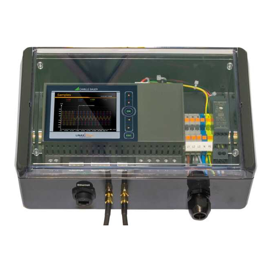
3.2 System overview The base unit LINAX PQ5000CL monitors centrally the power quality of the distribution system and collects, synchronized to the voltage, the current information of the current modules for state monitoring and load flow analysis of the individual feeders. Two version of the basic unit are available: Version Image Description... -
Page 8: Available Measurement Data
3.3 Available measurement data Voltage quality The device provides all necessary data for voltage quality assessment according to the standards EN 50160 or IEC 61000-2-2 / 2-4 / 2-12. User-defined limit-values may be defined and monitored as well. A compliance report (PQEasy Report) can be generated directly via the website of the device. The events frequency deviation, voltage dip / swell / interruption and rapid voltage change (RVC) can be monitored and recorded as sequences of RMS 1/2 values. -
Page 9: Mechanical Mounting
4. Mechanical mounting Please ensure that the operating temperature limits are not exceeded when determining the place of mounting (place of measurement). By installing, the device becomes part of an electrical power installation that must be designed, operated and maintained in accordance with country-specific regulations so that the installation is safe and provides prevention against fire and explosion as far as possible. -
Page 10: Wall Mounting Pq5000Cl-2 /- 3
4.2 Wall mounting PQ5000CL-2 /- 3 The field housing can be mounted on a wall with four screws (not included). Installation position as shown below. Drilling plan for field housing PM 1002670 000 00 System handbook PQ5000-Current Link 10/74... -
Page 11: Electrical Connections
5. Electrical connections Ensure under all circumstances that the leads are free of potential when connecting them! 5.1 General safety notes Please observe that the data on the type plate must be adhered to! The national provisions have to be observed in the installation and material selection of electric lines, e.g. -
Page 12: Possible Cross Sections And Tightening Torques Pq5000Cl-0 / -1
5.2 Possible cross sections and tightening torques PQ5000CL-0 / -1 Inputs L1(2), L2(5), L3(8), N(11), PE(16), I1(1-3), I2(4-6), I3(7-9), IN(10-12), power supply (13-14) • 1 x 0,5...6.0mm or 2 x 0,5...2.5mm Single wire • 1 x 20 AWG…9 AWG or 2 x 20 AWG…14 AWG •... -
Page 13: Voltage Connection Base Unit
5.4 Voltage connection base unit The voltage measurement inputs L1, L2 and L3 must originate at circuit breakers or fuses rated 5 Amps or less. This does not apply to the neutral connector. You have to provide a method for manually removing power from the device, such as a clearly labeled circuit breaker or a fused disconnect switch in accordance with IEC 60947-2 or IEC 60947-3. -
Page 14: Current Connection Base Unit
5.5 Current connection base unit Only for device versions with current measurement in the base unit PQ5000CL-001 / -101 No fuse may be connected upstream of the current measurement inputs! When using current transformers their secondary connectors must be short-circuited during installation and before removing the device. -
Page 15: Current Link Current Connections
5.6 Current Link current connections The Current Modules 3P and / or 3PN are arranged in a ring. The connection of the individual elements of the ring is done using SMA connection cables. The SMA connection cables must not be kinked during assembly, as the conductors could be damaged. -
Page 16: Power Supply
Mounting of the junction box The connection housing of a current module can be fixed directly to a cable using cable ties. The junction box of a current module must not be mounted on bare conductors, nor must connecting cables be routed over bare live conductors. If there are bare connections or busbars in the immediate vicinity, the junction box and connecting cables must be secured in such a way that their metal parts cannot touch live, bare parts in the event that the fixing of the junction box or a connecting cable becomes detached unexpectedly. -
Page 17: Digital Input
5.8 Digital input The device PQ5000CL-0/-1 provides a standard passive digital input. Usage of the standard digital input ► Status input ► Meter tariff switching Passive inputs (external power supply with 12 / 24 VDC required) The power supply shall not exceed 30V DC! Technical data Input current <... -
Page 18: Modbus Interface Rs485
5.10 Modbus interface RS485 Using a PQ5000CL-0/-1 measurement data may be provided to a superior system via the Modbus interface. Hint: A device parameterization via Modbus interface is not supported. 1) One ground connection only. Rt: Termination resistors: 120 Ω each Rs: Bus supply resistors, This is possibly made within the for long cables (>... -
Page 19: Commissioning
6. Commissioning Before commissioning you have to check if the connection data of the device match the data of the plant (see nameplate). If so, you can start to put the device into operation by switching on the power supply and the measurement inputs. -
Page 20: Operating Led Of The Base Unit
6.2 Operating LED of the base unit The operating LED shows the present device state Procedure LED display Booting of device • Flashes green (1 Hz) • If successful: Change to static green display Firmware update • Change to update mode: Static red •... -
Page 21: Installation Check
6.4 Installation check The correct connection of the current and voltage inputs can be checked in two ways. a) Sense of rotation check: Using the sequence of the current and voltage phasors the sense of rotation is determined and compared to the configured one. The phase rotation indicator is arranged in the menu “Phasor diagram”. - Page 22 b) Phasor verification: The phasor diagram shows a technical visualization of the current and voltage phasors, using a counter-clockwise rotation, independent of the real sense of rotation. The diagram is always built basing on the voltage of the reference channel (direction 3 o’clock) Correct installation (expectation) •...
-
Page 23: Ethernet Installation
6.5 Ethernet installation 6.5.1 Settings Before devices can be connected to an existing Ethernet network, you have to ensure that they will not disturb the normal network service. The rule is: None of the devices to connect is allowed to have the same IPv4/v6 address than another device already installed The device supports both IPv4 and IPv6 communication. - Page 24 Network settings Ethernet interface IPv4: Subnet mask For a direct communication between device and PC both devices need to be in the same network when the subnet mask is applied: Example 1 decimal binary 11000000 10101000 00000001 01100101 192.168. 1.101 IP address 11111111 11111111 11111111 11100000...
- Page 25 IPv4: Mode >> DHCP If a DHCP server is available, alternatively the mode „DHCP“ or „DHCP, addresses only“ can be selected for the Standard interface. The device then gets all necessary information from the DHCP server. The difference between the two modes is that for “DHCP” also the DNS server address is obtained. The settings obtained from the DHCP server can be retrieved locally via the service menu.
-
Page 26: Connection Of The Standard Interface
Firewall Due to security reasons nowadays, each network is protected by means of a firewall. When configuring the firewall, you have to decide which communication is desired and which have to be blocked. The TCP port 502 for the Modbus/TCP communication normally is considered to be unsafe and is often disabled. This may lead to a situation where no communication between networks (e.g. -
Page 27: Communication Tests
6.6 Communication tests Via the service menu on the device website you may check if the selected network structure is valid. The device must be able to reach the DNS server via gateway. The DNS server then allows resolving the URL of the NTP server to an IP address. -
Page 28: Security System
6.9 Security system There are several security mechanisms implemented in the device which can be activated to provide a comprehensive access protection to all device data. The role-based access control (RBAC) system allows restricting the access to measured data, configuration settings and service functions to the rights granted to the present user. - Page 29 A maximum of 8 users is supported 3 pre-defined standard users • admin: A user with administrator rights (Default setting password: „CBM_1234“) • localgui: The standard user for the local display. Its permissions determine what can be displayed or changed via the built-in display without a user having to log in.
- Page 30 When defining / changing passwords the following restrictions must be considered: - Password length 8 up to 32 characters - At least three different types of characters must be used (uppercase, lowercase, numbers, special characters) CAUTION: If login credentials (user name and / or password) of users with write access to the security system are changed, this information must be kept safe.
- Page 31 Assignment of user rights The assignment of the user rights granted for operation is done via the menu Settings | Security system | Users and permissions: Measurements or settings can be displayed Measurements or settings cannot be displayed Settings can be changed Settings cannot be changed Field not selectable Change a user’s login credentials...
-
Page 32: User Log In / Out Via Website
6.9.2 User log in / out via website a) If “anonymous” has no granted permissions Via website Remarks 1) Enter user name and password 2) Press <ENTER> or select “Login” If successful, depending on the permissions of the user logged in, the appropriate website is displayed b) If “anonymous”... -
Page 33: User Log In / Out Via Local Display
6.9.3 User log in / out via local display a) If “localgui” has no granted permissions Locally Remarks No information is displayed on the screen. Press <ESC> to enter the login screen. 1) Press <OK> to enter the user name 2) Proceed to password using 3) Press <OK>... -
Page 34: Whitelisting Clients
Before HTTPS communication can be used a root certificate needs to be installed. The user can either use a Camille Bauer certificate (default setting) or its own customer certificate. This may be changed when defining the Settings of the Security system. -
Page 35: Audit Log (Syslog)
The imported certificate is valid for all devices of the PQ, AM, DM and CU series. Agree to install the certificate if the below security warning appears: Customer certificate You may also use a customer server certificate with a private key, but for that you first need to change the Settings of the Security system in the item Web Security. - Page 36 Example of a security log: The severity of each message is shown in a color code, which may also serve as filter criteria. Each entry into this list may, if activated, also be transferred to a central log-server using the SYSLOG protocol for security auditing.
-
Page 37: Operating The Device
7. Operating the device 7.1 Operating elements The operation of devices with display is performed by means of 6 keys: 4 keys for navigation ( , , , ) and for the selection of values OK for selection or confirmation menu display, terminate or cancel... -
Page 38: Measurement Displays And Used Symbols
7.3 Measurement displays and used symbols For displaying measurement information, the device uses both numerical and numerical-graphical measurement displays. Examples Measurement information Phasor diagram Instantaneous values of voltages and currents (here for Current Module CM1) with the associated phase angles. Phase sequence of voltages and currents and direction of energy flow. - Page 39 Incoming / outgoing / inductive / capacitive The device provides information for all four quadrants. Quadrants are normally identified using the roman numbers I, II, III and IV, as shown in the adjacent graphic. Depending on whether the system is viewed from the producer or consumer side, the interpretation of the quadrants is changing: The energy built from the active power in the quadrants I+IV can either been seen as delivered or consumed active energy.
-
Page 40: Resetting Measurement Data
7.4 Resetting measurement data • Meter contents may be individually set or reset during operation using the service menu • Recorded logger data can be individually reset via the service menu. This makes sense whenever the configuration of the quantities to record has been changed. 7.5 Configuration The configuration options of the device can be reduced on a customer-specific basis, so that certain parameters are predefined and cannot be changed... -
Page 41: Configuration Via Web Browser
• Data export scheduler: Via website you can setup tasks to be performed regularly. Each time such a task is running, it creates a data file to be transferred to a SFTP server and/or to be stored locally on the device. Via local configuration tasks can be enabled or disabled only. 7.5.2 Configuration via web browser It’s recommended to use either Google Chrome or Firefox as browser. - Page 42 Loading / saving configuration files The user can save the present device configuration on a storage media and reload it from there. The storage or load procedure varies depending on the browser used. The settings of the security system are not part of the configuration file. There is no way to transfer security settings from one device to another.
-
Page 43: Pq Monitoring
7.6 PQ monitoring Power quality monitoring provides both a statistical evaluation, allowing an assessment of compliance with standards (e.g. EN 50160) or supply contracts, as well as records of events in the grid (e.g. power voltage dips). This facilitates the analysis of causes and effects. Compliance reports may also be created directly via the website of the device. - Page 44 Mains signalling voltage The device monitors mains signalling voltages, which are transmitted in the supply system for control purposes, and records them as events. Typically, these are ripple control signals. The user can define the frequency of the signalling voltage, the threshold and hysteresis (related to the nominal voltage) as well as the recording duration in multiples of the measurement interval of 10/12 cycles.
-
Page 45: Pq Statistic
7.6.2 PQ statistic Power quality (PQ) is assessed by a comparison between the PQ parameters measured by the device and the limits of a contract agreed upon. The assessment period is usually at least one week to consider possible variations between weekdays and weekends. Via its website the device can perform an assessment of the measured PQ parameters in accordance with the following standards: EN 50160... -
Page 46: Provision Of Pq Data
7.6.3 Provision of PQ data The device can create PQ related data, such as PQ events or PQ statistic, using the standard format PQDIF (Power Quality Data Interchange Format). The automatic or event-driven generation of such files can be defined via the Data export scheduler in the Settings menu. -
Page 47: Data Recording
7.7 Data recording The device stores long-term recordings of measurement progressions, events and PQ statistics. Some of these recordings provide predefined contents; some is based on user-defined contents. In addition, file-based information may be periodically created using the data export scheduler. - Page 48 Display matrix on the local display using the example of PQ3000 Restriction of the quantities to display on the local display The user can adapt the displayed information to its needs. Once the graphic is displayed, the setting window for the selection of the quantities to display is entered by pressing <OK>. Voltage display Current display Mixed display...
- Page 49 Display of PQ events (WEB-GUI) As with the local GUI, recorded events are available in the form of a logbook. Events may be filtered by event type and event date. By selecting a list entry, the graphical display of the measured values during this event is entered. List of PQ events Graphical display of a PQ event By selecting a time range via left...
-
Page 50: Pq Statistic
7.7.2 PQ statistic From the PQ statistic it is very easy to see whether the limits of the monitored criteria are respected or not. Each criterion is represented by a bar, which itself may be composed of multiple color components: Requirement fulfilled Missing data Requirement not fulfilled... - Page 51 Display of PQ statistic (locally) Selection via Main menu | PQ statistic The PQ statistic is always displayed for the past seven days. Another time range cannot be selected. The standard to be used for the assessment of the statistic can be changed by selecting the entry “Standard”.
- Page 52 Creating a compliance report via the device website – PQ-Easy Report a compliance report in PDF format can be created. 1. Select assessment period: At least 1 week 2. Select standard which compliance needs to be proven 3. Select content of report (3 levels) 4.
- Page 53 Example of a compliance report a) Overview b) Details c) Events PM 1002670 000 00 System handbook PQ5000-Current Link 53/74...
-
Page 54: Measurement Information In File Format
7.8 Measurement information in file format Using the data export scheduler, measurement information may be provided also in file format. Such files can then: • periodically or event-driven being sent to a SFTP server • locally stored in the device and downloaded via webpage The management and setup of tasks for providing files is done via the item Data export | Data export scheduler in the settings menu. -
Page 55: Creating Periodic File Data
7.8.2 Creating periodic file data (This function may be missing in customer-specific versions) In addition to the predefined tasks new tasks can be setup for creating CSV files with mean-values information at regular intervals. These files may then be stored locally and / or pushed to a SFTP server. By selecting “Add task”... -
Page 56: Accessing File Information Via Webpage
CSV settings CSV files are intended for transmitting statistics of mean values. You may adjust the below parameters to adapt the file format and the content of the created files to your requirements. • The Separator separates the individual entries on a text line for later display in table form. •... -
Page 57: Periodical Sending To A Sftp Server
Files in the pqdif folder are stored in a hierarchical time structure (year, month, day). By selecting the desired date and double-clicking on the appropriate file, a PQDIF may be easily downloaded. 7.8.4 Periodical sending to a SFTP Server If in the data export scheduler the sending to an SFTP server was selected as action, the appropriate files will be sent periodically to the SFTP server defined in the settings of the communication. -
Page 58: Evaluation Of The Pqdif Files
7.8.5 Evaluation of the PQDIF files For the analysis of the data of the PQDIF files either the SmartCollect PM20 software (not included in the scope of delivery) or a free tool with limited functionality, such as the PQDiffractor from Electrotek Concepts (http://www.pqview.com/pqdiffractor/;... -
Page 59: Service, Maintenance And Disposal
8. Service, maintenance and disposal 8.1 Calibration and new adjustment Each device is adjusted and checked before delivery. The condition as supplied to the customer is measured and stored in electronic form. The uncertainty of measurement devices may be altered during normal operation if, for example, the specified ambient conditions are not met. -
Page 60: Technical Data
9. Technical data Measurement inputs Voltage base unit PQ5000CL-0/-1 Nominal voltage: 57,7…400 V (UL: 347 V ), 100...693 V (UL: 600 V Range maximum: 520 V , 900 V (sinusoidal) Measurement category: 600V CAT III Uncertainty: ± 0,1% Consumption: ≤ U / 1,54 MΩ... - Page 61 Systems: 4-wire, unbalanced Nominal frequency: 42...50...58Hz Sampling rate: 18 kHz (U), 54 kHz (I) Internal data memory: 16 GB Power Quality Type of device: (IEC 62586-1) PQI-x FI1: Power Quality Instrument – Class A; Fixed installation; Indoor environment with uncontrolled temperature variations (1) x=S (PQ1000), x=A (PQ3000, PQ5000) Measurement cycle: 10 cycles at 50Hz, approx.
- Page 62 Power supply via terminals 13-14 (PQ5000CL-0/-1), internally (PQ5000CL-2/-3) Nominal voltage: 100…230V AC 50/60Hz / DC ±15% (PQ5000CL-0/-1) 100…230V AC 50/60Hz ±15% (PQ5000CL-2/-3) Overvoltage category: OVC III Consumption: ≤ 27VA, ≤ 12W (PQ5000CL-0/-1) ≤ 60VA (PQ5000CL-2/-3) Available inputs / outputs and functional extensions Base unit •...
- Page 63 Mechanical attributes Housing material: Polycarbonate (Makrolon) Flammability class: V-0 acc. UL94, non-dripping, free of halogen Weight: 400 g (PQ1000), 800 g (PQ3000), 600g (PQ5000) Dimensions: Dimensional drawings Vibration withstand (test according to DIN EN 60 068-2-6) Acceleration: • Device with display: ± 0.25 g (operating); 1.20 g (storage) •...
- Page 64 Applied regulations, standards and directives IEC/EN 61010-1 Safety regulations for electrical measuring, control and laboratory equipment IEC/EN 61000-4-30 Ed.3 Power quality measurement methods IEC/EN 61000-4-7 General guide on harmonics and interharmonics measurements IEC/EN 61000-4-15 Flickermeter - Functional and design specifications IEEE 1159.3 Recommended Practice for the Transfer of Power Quality Data IEC 62586-1 Ed.2...
-
Page 65: Dimensional Drawings
10. Dimensional drawings All dimensions in [mm] LINAX PQ5000CL-0 / -1 LINAX PQ5000CL-2 / -3 PM 1002670 000 00 System handbook PQ5000-Current Link 65/74... -
Page 66: Annex
Annex A Description of measured quantities A1 Basic measurements The basic measured quantities are calculated each 200ms by determining an average over 10 cycles at 50Hz. The subsequent listed values are available for each installed Current Module and the base unit (with option «Current measurement in the base unit»). -
Page 67: A2 Harmonic Analysis
Zero displacement voltage U Starting from the generating system with star point E (which is normally earthed), the star point (N) on load side is shifted in case of unbalanced load. The zero displacement voltage between E und N may be determined by an addition of the voltage phasors of the three phases: = - (U... -
Page 68: A3 System Imbalance
A3 System imbalance Measured quantity UR1: Positive sequence [V] UR2: Negative sequence [V] U0: Zero sequence [V] U: Imbalance UR2/UR1 U: Imbalance U0/UR1 Imbalance in three-phase systems may occur due to single-phase loads, but also due to failures, such as e.g. -
Page 69: B Display Matrices
B Display matrices B0 Used abbreviations for the measurements Instantaneous values Name Measurement identification Unit Description Voltage system TRMS Voltage between phase L1 and neutral TRMS Voltage between phase L2 and neutral TRMS Voltage between phase L3 and neutral TRMS Voltage between phases L1 and L2 TRMS Voltage between phases L2 and L3... - Page 70 Graphical measurement displays Name Presentation Description PHASOR Graphic: All current and voltage phasors Phase sequence display for the voltages and the PHASE_SEQ currents of a Current Module, here CM1 Graphic: Odd harmonics 3 up to 49 + Total HO_UX Harmonic Distortion of all voltages Graphic: Odd harmonics 3rd up to 49th + Total HO_IX (as HO_IX)
- Page 71 INST_PQS Instantaneous power values per phase INST_SYS Instantaneous values of system quantities System handbook PQ5000-Current Link PM 1002670 000 00 71/74...
-
Page 72: B1 On-Site Display
B1 On-site display CM3 ..CM10 PHASOR INST_UI INST_PQS INST_SYS PHASE_SEQ PM 1002670 000 00 System handbook PQ5000-Current Link 72/74... -
Page 73: C Fcc Statement
Camille Bauer AG. The correction of interference caused by such unauthorized modification, substitution or attachment will be the responsibility of the user. -
Page 74: Index
Index Base quantities ..........66 Meters .............. 68 Commissioning ............. 19 System unbalance ........... 68 Compliance report ..........52 Mechanical mounting ..........9 Configuration Menu operation ............ 37 Menu ..............40 NTP ..............25 Device overview ............6 Dimensional drawing ..........65 Display matrices............
Need help?
Do you have a question about the LINAX PQ5000-CURRENT LINK and is the answer not in the manual?
Questions and answers