Table of Contents
Advertisement
Quick Links
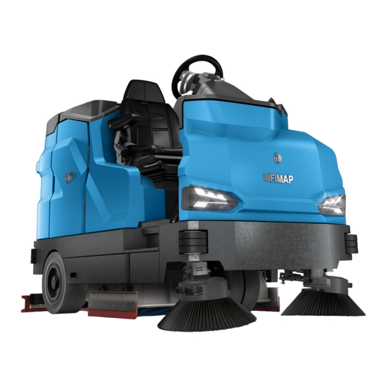
GMG B
PROFESSIONAL SCRUBBING MACHINES
USE AND MAINTENANCE MANUAL
ORIGINAL INSTRUCTIONS DOC. 10114166 - Ver. AA - 03-2022
The design elements and contents of this manual, including its structure, texts, graphics, images and logo, are the exclusive property of FIMAP S.P.A..
They are protected, both collectively and individually, by the current regulations regarding intellectual property (including copyright laws), and cannot be either wholly or partially copied or imitated. Any
reproduction, reprocessing, distribution or dissemination is strictly prohibited.
Advertisement
Table of Contents

Related Manuals for Fimap GMG B


Summary of Contents for Fimap GMG B
- Page 1 ORIGINAL INSTRUCTIONS DOC. 10114166 - Ver. AA - 03-2022 The design elements and contents of this manual, including its structure, texts, graphics, images and logo, are the exclusive property of FIMAP S.P.A.. They are protected, both collectively and individually, by the current regulations regarding intellectual property (including copyright laws), and cannot be either wholly or partially copied or imitated. Any...
-
Page 3: Table Of Contents
CONTENTS CONTENTS ......................3 DEFINITION OF LEVELS OF WARNING ............7 GENERAL SAFETY REGULATIONS ..............7 GENERAL DESCRIPTION ................. 8 SYMBOLS USED IN THE MANUAL ..................8 TARGET GROUP ........................9 PURPOSE AND CONTENT OF THE USER AND MAINTENANCE MANUAL ....... 9 STORING THE USE AND MAINTENANCE MANUAL ............ - Page 4 WORKING PROGRAMS (PRO VERSION) ............61 ECO MODE WORKING PROGRAM (PRO VERSION) ............61 POWER MODE WORKING PROGRAM (PRO VERSION) ........... 62 MANUAL MODE WORKING PROGRAM (PRO VERSION) ..........63 PROGRAM ZONE WORKING PROGRAM (PRO VERSION) ..........63 WORKING PROGRAMS (PLUS VERSION) ............ 64 ECO MODE WORKING PROGRAM (PLUS VERSION) ............
- Page 5 ADJUSTING THE FORWARD SPEED (PLUS VERSION) ..........102 ADJUSTING THE DETERGENT SOLUTION FLOW (PLUS VERSION) ......103 VACUUM SYSTEM PERFORMANCE ADJUSTMENT (PLUS VERSION) ......104 SMART DRYING MODE (PLUS VERSION) ............... 105 WORKING HEADLIGHTS (PLUS VERSION) ..............105 SCRUBBING SIDE BRUSH (PLUS VERSION) ..............106 ALARM SCREEN (PLUS VERSION) ..................
- Page 6 DRAINING THE RECOVERY TANK ..................146 CLEANING THE WATER SYSTEM FILTER ..............147 EMPTYING THE SOLUTION TANK ..................148 CLEANING THE FILTER ON THE AUTOMATIC CHEMICAL DETERGENT MANAGEMENT SYSTEM (OPTIONAL) ......................148 CHEMICAL DETERGENT TANK EMPTYING (OPTIONAL) ..........149 CLEANING THE FILTER ON THE DETERGENT SOLUTION RECYCLING SYSTEM (OPTIONAL) ........................
-
Page 7: Definition Of Levels Of Warning
DEFINITION OF LEVELS OF WARNING DANGER: indicates an imminent dangerous situation that, unless avoided, will result in death or serious injuries. WARNING: Indicates a potentially dangerous situation that, unless avoided, could cause death of serious injury. ATTENTION: Indicates a potentially dangerous situation that, unless avoided, could cause slight or moderate injuries. -
Page 8: General Description
GENERAL DESCRIPTION The descriptions contained in this document are not binding. The company therefore reserves the right to make any modifications at any time to elements, details, or accessory supply, as considered necessary for reasons of improvement or manufacturing/commercial requirements. The reproduction, even partial, of the text and drawings contained in this document is prohibited by law. -
Page 9: Target Group
The following document must be stored in its special pouch close to the machine, protected from liquids and anything else that could compromise its legibility. If the document is lost or becomes illegible with wear, contact the nearest FIMAP service centre to obtain a new one. -
Page 10: On Consignment Of The Machine
If this is the case, the shipping agent must ascertain the extent of the damage at once, and notify the nearest FIMAP service centre. It is only by prompt action of this type that the missing material can be obtained, and compensation for damage successfully claimed. -
Page 11: Serial Number Plate
SERIAL NUMBER PLATE The serial number plate is located near the driver's seat, at the rear of the steering column, and indicates the machine's general characteristics, including its serial number. The serial number is a very important piece of information and should always be provided together with any request for assistance or when purchasing spare parts. -
Page 12: Main Machine Components
MAIN MACHINE COMPONENTS Front headlights Right rear door Front bumper wheels Brush head inspection door Front wheels Right rear motorwheel Rung Rear headlights Side brush head (optional) Solution tank drain hose Central brush brush head recovery tank drainage tube Page 12 of 172... - Page 13 Inspection footboard and recovery tank Rear bumper wheels maintenance. Squeegee bumper wheel Collision avoidance sensor (optional) Squeegee Solution tank filler cap Chemical detergent filler cap (optional) Solution tank quick filling kit hose Chemical detergent tank MAX level connector (optional) indicator (optional) Solution tank fill volume level hose.
- Page 14 Chemical detergent tank MIN level POWER MODE working program indicator (optional) activation lever. Brush head and water system filter Automatic technical assistance request inspection door button (optional) Reverse gear function control lever Steering wheel Driver's seat Detergent solution delivery control Key-operated main switch lever.
- Page 15 USB port Brake pedal Service lights switch (optional) accelerator pedal Horn button Command display Membrane panel (Plus version) Control pushbutton panel Page 15 of 172...
-
Page 16: Technical Data
[IEC 60335-2-72; IEC 62885-9; ISO 5349-1] Whole-body vibrations [IEC 60335-2-72; IEC 62885-9; ISO 2631-1] Vibration measurement uncertainty ±4% ±4% N.B.: for all other technical data, contact the FIMAP service department by writing to service@fimap.com, or visit the website www.fimap.com. Page 16 of 172... - Page 17 [IEC 60335-2-72; IEC 62885-9; ISO 5349-1] Whole-body vibrations [IEC 60335-2-72; IEC 62885-9; ISO 2631-1] Vibration measurement uncertainty ±4% ±4% N.B.: for all other technical data, contact the FIMAP service department by writing to service@fimap.com, or visit the website www.fimap.com. Page 17 of 172...
-
Page 18: Symbols Used On The Machine
SYMBOLS USED ON THE MACHINE Extra pressure activation/deactivation lever position symbol: Applied to the brush head extra pressure activation/deactivation lever. Reverse gear activation/deactivation lever position symbol: Applied to the reverse gear activation/deactivation lever. Symbol for maximum temperature for filling the solution tank: Applied to the left-hand side of the machine's solution tank to indicate the maximum temperature of the water that can be used to safely fill the solution tank. - Page 19 Chemical detergent symbol: Applied to the left-hand side of the machine's solution tank to indicate the chemical detergent tank. This symbol is only present on versions equipped with automatic chemical product management. recovery tank drainage hose symbol: Applied to the right rear of the machine to identify the recovery tank drainage hose.
-
Page 20: Labels Used On The Machine
LABELS USED ON THE MACHINE USB port label: Applied to the lower part of the steering column to indicate the location of the two USB ports. Machine main switch label: Applied to the lower part of the steering column to indicate the location of the machine's main switch. - Page 21 Tap control lever label: Applied to the front of the solution tank to indicate the tap control lever. Daily maintenance label: Applied to the front of the solution tank, near the tap control lever, to indicate the need to close the tap at the end of the work activities, and to carry out daily maintenance on the squeegee and the filters present on the machine.
- Page 22 Label indicating the need to read the Use and Maintenance Manual: Applied to the front of the steering column to indicate the need for the user to read the user and maintenance manual before operating the machine. Horn button label: Applied to the left side of the steering column to identify the machine's horn button.
- Page 23 Rated voltage label: Applied to the electrical system connector support to indicate the machine's rated voltage value. Label warning about the risk of crushed hands: Applied to the solution tank to indicate the areas where hand crushing hazards are present. Chemical pH range label (FSS versions): Applied near the detergent tank's cap to indicate the chemical product pH range within which the FSS system operates without...
- Page 24 Battery pack warning label: Applied to the inside of the battery pack lid to warn that the cells could release highly flammable hydrogen gas during the recharging phase. Battery pack charging instructions label: Applied to the inside of the battery pack lid to indicate the procedures to be followed in order to properly charge the battery pack.
- Page 25 Treading ban label: Applied to the lateral inspection doors to identify the surfaces that must not be trodden upon (risk of personal injury or damage to the machine). Label indicating that touching the brush when moving is prohibited: Applied to the left and right sides of the brush head to indicate the prohibition to place your hands in the vicinity of the brush head while the brush is in motion.
- Page 26 Inspection footboard-recovery tank maintenance label: Applied to the rear of the machine to indicate the platform used to inspect and maintain the recovery tank. Lower limb and hand crushing hazard label: Applied at the rear of the machine to warn the user that there is a risk of crushing the lower limbs and hands when the squeegee is in motion.
- Page 27 Suction motor filter maintenance label: Applied to the inside of the recovery tank's lid to remind the user to perform maintenance on the suction motor filter after every machine use. recovery tank drainage tube label: Applied to the rear of the machine to indicate the recovery tank's drainage tube.
- Page 28 recovery tank cleaning gun label (optional) Applied inside the right rear lid to indicate the support hook for the recovery tank's cleaning gun. Page 28 of 172...
-
Page 29: Control Station (Pro Version)
CONTROL STATION (PRO VERSION) The machine has an easy to use and intuitive control station, it is comprised of mainly the following: Control panel, see “CONTROL PUSHBUTTON PANEL (PRO VERSION)” on page 29. Control panel, see “CONTROL DISPLAY (PRO VERSION)” on page 30. POWER working program activation pad, see “POWER MODE WORKING PROGRAM (PRO VERSION)”... -
Page 30: Control Display (Pro Version)
CONTROL DISPLAY (PRO VERSION) The control display consists of the following: ECO-MODE working program control button, see “ECO MODE WORKING PROGRAM (PRO VERSION)” on page 61. Control display. Forward speed performance adjustment button, see “ADJUSTING THE FORWARD SPEED (PRO VERSION)” on page 96. - Page 31 The control display consists of the following: Graphic symbol used to identify the residual battery charge, see “BATTERY BOX CHARGE LEVEL INDICATOR (PRO VERSION)” on page 85. Numeric symbol used to identify the residual battery charge, see “BATTERY BOX CHARGE LEVEL INDICATOR (PRO VERSION)” on page 85.
-
Page 32: Control Station (Plus Version)
CONTROL STATION (PLUS VERSION) The machine has an easy to use and intuitive control station, it is comprised of mainly the following: Control panel, see “CONTROL PUSHBUTTON PANEL (PLUS VERSION)” on page 32. Membrane pushbutton panel, see “MEMBRANE PUSHBUTTON PANEL (PLUS VERSION)” on page Control panel, see “CONTROL DISPLAY (PLUS VERSION)”... -
Page 33: Control Display (Plus Version)
ECO working program activation button, see “ECO MODE WORKING PROGRAM (PLUS VERSION)” on page COMFORT working program activation button, see COMFORT MODE WORKING PROGRAM. DYNAMIC working program activation button, see DYNAMIC MODE WORKING PROGRAM. HEAVY working program activation button, see “HEAVY MODE WORKING PROGRAM (PLUS VERSION)” on page 68. - Page 34 Text indicator. Menu screen activation button, see the user interface configuration manual, document number 10114635. Detergent solution performance level indicator, see “MANUAL MODE WORKING PROGRAM (PLUS VERSION)” on page 70. Rear view camera screen activation button, see “REAR VIEW CAMERA (PLUS VERSION)” on page 109. Vacuum system performance level indicator, see “MANUAL MODE WORKING PROGRAM (PLUS VERSION)”...
-
Page 35: Preparation Of Machine
PREPARATION OF MACHINE MACHINE SAFETY Machine PRO version: CAUTION: it is recommended to wear the appropriate PPE (Personal Protective Equipment), suitable for the work to be carried out. Open the right inspection door (1) (Fig.1). Check that the right gearmotor electric brake is activated. The lever (2) must not be in its locked position, otherwise, unlock it by pulling it towards you and moving it downwards (Fig.2). - Page 36 Make sure that the brush head is in the rest position; if this is not the case, press the button (6) on the control panel (Fig.7). N.B.: when the brush head is in the rest position, the LED (8) on the button (6) is off. 10.
- Page 37 Check that also the right gearmotor electric brake is activated. The lever (2) must not be in its locked position, otherwise, unlock it by pulling it towards you and moving it downwards (Fig.4). Make sure the solution tank is empty. If this is not the case, empty it. See “EMPTYING THE SOLUTION TANK” on page 148 on page .
- Page 38 To ensure that work is carried out in the best safety conditions, proceed as follows: Get off the machine. Remove the key from the instrument panel. Get off the machine. CAUTION: do not position your foot above the lateral brush head lid while the machine is descending. Grasp the handle (1) and turn the battery compartment lid (2) to its maintenance position (Fig.1).
-
Page 39: How To Move The Machine
HOW TO MOVE THE MACHINE Machine PRO version: CAUTION: it is recommended to wear the appropriate PPE (Personal Protective Equipment), suitable for the work to be carried out. Open the right inspection door (1) (Fig.1). Check that the right gearmotor electric brake is activated. The lever (2) must not be in its locked position, otherwise, unlock it by pulling it towards you and moving it downwards (Fig.2). - Page 40 Make sure that the brush head is in the rest position; if this is not the case, press the button (6) on the control panel (Fig.7). N.B.: when the brush head is in the rest position, the LED (7) on the button (6) is off. 10.
- Page 41 ATTENTION: If the electric brake is not properly engaged, the alarm symbol will appear on the control display (Fig. 6) and will remain visible until all the electric brakes have been properly engaged. N.B.: when the electric brake is deactivated, traction is inhibited. Allarme 88 Trazione Elettrofreno...
- Page 42 ATTENTION: to prevent the lid from turning, insert the retainer (5) into the slot (6) (Fig.4). ATTENTION: the following operations must be carried out by qualified personnel. Incorrect operations could result in machine malfunctions. Disconnect the machine's electrical system wiring connector (7) from the connector on the power cable coming from the battery box (Fig.
-
Page 43: How To Move The Machine With The Traction In Neutral
HOW TO MOVE THE MACHINE WITH THE TRACTION IN NEUTRAL The phases for moving the machine with the traction system in neutral are as follows: Perform all the operations required to secure the machine. See “MACHINE SAFETY” on page 35. Open the right inspection door (1) (Fig.1). -
Page 44: Traction Electric Brake Activation
TRACTION ELECTRIC BRAKE ACTIVATION The phases for activating the traction electric brake are as follows: CAUTION: it is recommended to wear the appropriate PPE (Personal Protective Equipment), suitable for the work to be carried out. Open the right inspection door (1) (Fig.1). Activate the right gearmotor electric brake, the lever (2) must not be in its locked position, otherwise, release it by pulling it towards you and moving it down (Fig.2). -
Page 45: Type Of Battery Pack To Be Used
When the battery pack is drained, it must be disconnected by a FIMAP service centre technician or a properly trained and specialised worker; using a suitable lifting device, remove the battery pack from the machine and take it to a suitable disposal centre. -
Page 46: Inserting Water System Filter
ATTENTION: to prevent the lid from turning, insert the retainer (3) into the slot (4) (Fig.2). ATTENTION: the following operations must be carried out by qualified personnel. An incorrect connection of the connector may cause a malfunction of the device. Connect the battery charger cable's connector (5) to the connector on the power cable coming from the battery pack (Fig.3). -
Page 47: Detergent Solution
N.B.: The O-ring gasket in the filter cartridge should be inserted into its seat in the cap. Screw the cap (4) onto the body of the detergent solution filter (Fig.4). DETERGENT SOLUTION Proceed as follows to fill the solution tank with water: Take the machine to the usual place for filling the solution tank. - Page 48 getting inside, which can cause the machine's water system to malfunction. Fill the solution tank. N.B.: the amount of solution inside the tank is indicated by the coloured ball inside the level tube (7) on the left-hand side of the machine (Fig.6). N.B.: the solution tank can also be filled with the quick-fill system (FFF).
-
Page 49: Assembling The Brush Head Brushes Or Drive Discs
N.B.: The upper bulb indicates the detergent tank's maximum fill level; the lower bulb indicates the minimum level, below which the automatic system will not function properly. ATTENTION: always use detergents which have a manufacturer's label that indicates that they are suitable for use with floor scrubbing machines. - Page 50 Insert the brush (4) in the brush holder plate (5) (Fig.4). Turn the brush anti-clockwise until the three buttons (6) on the brush enter the notches (7) on the brush holder plate (Fig.5). Turn the brush quickly and firmly in order to push the button towards the retainer spring (8) and lock it in place (Fig.5).
-
Page 51: Assembling The Brush Head Abrasive Pad
ASSEMBLING THE BRUSH HEAD ABRASIVE PAD To mount the abrasive pad on the drive discs on the brush head, do the following: Take the machine to the maintenance area. Perform all the operations required to secure the machine. See “MACHINE SAFETY” on page 35. CAUTION: it is recommended to wear the appropriate PPE (Personal Protective Equipment), suitable for the work to be carried out. -
Page 52: Assembly Of The Side Brush Head Brush Or Drive Disc (Optional)
ASSEMBLY OF THE SIDE BRUSH HEAD BRUSH OR DRIVE DISC (OPTIONAL) To assemble the lateral brush on the machine, do the following: Take the machine to the maintenance area. Perform all the operations required to secure the machine. See “MACHINE SAFETY” on page 35. CAUTION: it is recommended to wear the appropriate PPE (Personal Protective Equipment), suitable for the work to be carried out. -
Page 53: Assembly Of The Brush Head Side Splash Guard Support
ASSEMBLY OF THE BRUSH HEAD SIDE SPLASH GUARD SUPPORT To assemble the brush head side splash guards on the machine, do the following: Take the machine to the maintenance area. Perform all the operations required to secure the machine. See “MACHINE SAFETY” on page 35. CAUTION: it is recommended to wear the appropriate PPE (Personal Protective Equipment), suitable for the work to be carried out. -
Page 54: Assembling The Squeegee
ASSEMBLING THE SQUEEGEE To mount it the squeegee on the machine, do the following: Take the machine to the maintenance area. Perform all the operations required to secure the machine. See “MACHINE SAFETY” on page 35. CAUTION: it is recommended to wear the appropriate PPE (Personal Protective Equipment), suitable for the work to be carried out. -
Page 55: Adjustment Of The Driver's Seat (Comfort Seat)
• FIMAP assumes no responsibility for the improper assembly, use, and/or maintenance of the seat. • All seat adjustments must be performed and checked with the operator seated and before starting the machine: Never perform these operations with the machine running. - Page 56 • Do not perform any maintenance operations on the safety belt other than regular cleaning. • Keep the belts, reels and buckles clean, and make sure that there are no foreign objects inside the buckles that could prevent the clip from being properly retained by the buckle.
- Page 57 ATTENTION: the adjustment described above should be performed with the operator seated, so that the seat is bearing their weight. ATTENTION: The seat should always be positioned using the pedals as a reference. N.B.: adjust the distance of the seat so that the brake pedal reaches the end of its stroke when pressed. N.B.: the distance should be adjusted so that the knees are slightly bent (about 120°) when the pedals are fully pressed to the floor.
- Page 58 WEARING THE SAFETY BELT CORRECTLY: the machine comes equipped with a sub-abdominal safety device, which allows the operator to remain anchored to the driver's seat. To secure the safety belt, you must first be sitting in the driver's seat; take the mobile part of the belt, wrap it round the abdomen and insert the mobile part in the slit in the fixed part.
-
Page 59: Work Preparation Checklist
Check the condition of the squeegee vacuum tube. “CLEANING THE SQUEEGEE VACUUM HOSE” on page 142. Check that the gasket on the recovery tank's lid is not If the gasket is damaged, contact the FIMAP service centre □ damaged or worn. to have it replaced. - Page 60 THE DETERGENT SOLUTION RECYCLING SYSTEM inside the recovery tank. (OPTIONAL)” on page 150. Check the horn; the front and rear lights; the safety lights If any anomalies are encountered, contact the FIMAP □ and the alarm (if installed). service centre.
-
Page 61: Working Programs (Pro Version)
WORKING PROGRAMS (PRO VERSION) The machine can be used with the following working programs: 1. ECO MODE: for light maintenance cleaning tasks, using fewer resources and operating at a low noise level (see the “ECO MODE WORKING PROGRAM (PRO VERSION)” on page 61). 2. -
Page 62: Power Mode Working Program (Pro Version)
N.B.: By selecting the ECO MODE working program, the working parameters (machine speed; the force exerted on the brushes; the performance of the suction motor; the flow of the detergent solution) are automatically changed. To modify the parameters of the work program, see the USER INTERFACE CONFIGURATION GUIDE document. -
Page 63: Manual Mode Working Program (Pro Version)
MANUAL MODE WORKING PROGRAM (PRO VERSION) With the MANUAL MODE working program, it is the operator who evaluates and chooses the parameters based on the cleaning requirements that arise during the course of the work activities. To switch from the ECO MODE or POWER MODE or PROGRAM ZONE program to the MANUAL ZONE program, simply change one of the performance levels. -
Page 64: Working Programs (Plus Version)
WORKING PROGRAMS (PLUS VERSION) Six types of programs are already stored in the function board memory, which can be used to facilitate machine use by the operator. In the working programs, the performance levels of the parameters: • machine forward speed; •... -
Page 65: Eco Mode Working Program (Plus Version)
ECO MODE WORKING PROGRAM (PLUS VERSION) The POWER MODE working program can be used for light maintenance work. The ECO MODE program is a program which guarantees the best possible performance in terms of consumption and cleaning. The ECO MODE working program can be activated by pressing the button (1) on the membrane pushbutton panel (Fig.1). -
Page 66: Comfort Mode Working Program (Plus Version)
COMFORT MODE WORKING PROGRAM (PLUS VERSION) The COMFORT MODE working program can be used for ordinary, non-aggressive cleaning suitable for daily use. The COMFORT MODE working program can be activated by pressing the button (1) on the membrane pushbutton panel (Fig.1). N.B.: as soon as the button (1) is pressed, the control display (Fig.2) shows the screen dedicated to the COMFORT MODE working program and the program name is displayed in the circular symbol (2). -
Page 67: Dynamic Mode Working Program (Plus Version)
DYNAMIC MODE WORKING PROGRAM (PLUS VERSION) The DYNAMIC MODE working program can be used for ordinary cleaning that aims to achieve greater productivity, it permits performing daily cleaning operations quickly. The DYNAMIC MODE working program can be activated by pressing the button (1) on the membrane pushbutton panel (Fig.1). -
Page 68: Heavy Mode Working Program (Plus Version)
HEAVY MODE WORKING PROGRAM (PLUS VERSION) The HEAVY MODE working program can be used for operations requiring considerable scrubbing power and for cleaning particularly dirty environments . The HEAVY MODE working program can be activated by pressing the button (1) on the membrane pushbutton panel (Fig.1). -
Page 69: Zone Mode Working Program (Plus Version)
ZONE MODE WORKING PROGRAM (PLUS VERSION) The ZONE MODE working program can be used to help the operator carry out the intervention correctly . To activate the ZONE MODE working program, proceed as follows: Press the button (1) on the membrane pushbutton panel (Fig.1). Select the working zone to be loaded (Fig.2), press “OFFICE”, for example, on the control display (2). -
Page 70: Manual Mode Working Program (Plus Version)
MANUAL MODE WORKING PROGRAM (PLUS VERSION) The MANUAL MODE program is a program where it is the operator who freely evaluates and chooses the parameters based on the cleaning requirements that arise during the course of the operation. There are two ways to switch to the ZONE MODE working program while working: By pressing the membrane pushbutton panel (Fig.1), pressing one of the four buttons: Forward speed performance level change button, see “ADJUSTING THE FORWARD SPEED (PLUS VERSION)”... -
Page 71: Power Mode Working Program (Plus Version)
0000.00 POWER MODE WORKING PROGRAM (PLUS VERSION) The POWER MODE working program can be used if small areas with stubborn dirt are found during an intervention, therefore it is useful to temporarily leave the configuration that is being used in order to use maximum scrubbing force to remove the localised dirt. -
Page 72: Working Mode (Pro Versions)
WORKING MODE (PRO VERSIONS) TRANSFER WORKING MODE (PRO VERSION) In the TRANSFER working mode, both the brush head and the squeegee are in their resting positions. This working mode is used to transfer the machine from the work site to the maintenance site. To use the machine in transfer mode, do the following: Carry out all the checks listed in the “WORK PREPARATION CHECKLIST”... -
Page 73: Scrubbing Machine Working Mode (Pro Version)
SCRUBBING MACHINE WORKING MODE (PRO VERSION) In the SCRUBBING MACHINE working mode, the brush head and squeegee are in their working positions. This working mode is used to scrub and dry the floor at the same time. To use the machine in scrubbing machine working mode, do the following: Carry out all the checks listed in the “WORK PREPARATION CHECKLIST”... -
Page 74: Prescrubbing Working Mode (Pro Version)
N.B.: the brush motors; the solenoid valve, and the detergent solution pump only begin functioning once the brush head is in its working position. N.B.: the suction motors are only activated once the squeegee is in its working position. N.B.: if the drive pedal (5) is released while working, once the reset delay time has elapsed, both the brush head as well as the squeegee are automatically moved to the intermediate rest position. - Page 75 The machine is now in the transfer working mode. By selecting one of the working programs like ECO MODE; POWER MODE; or PROGRAM ZONE, the SCRUBBING MACHINE working mode will be enabled. N.B.: for more information on the working program types, see the “WORKING PROGRAMS (PRO VERSION)”...
-
Page 76: Drying Working Mode (Pro Version)
N.B.: the value for the reset delay time is selected on the function card's parameter list. DRYING WORKING MODE (PRO VERSION) In the DRYING working mode, only the squeegee is in its working position, with the brush head remaining in its resting position. - Page 77 N.B.: as soon as it is pressed, the brush head is automatically moved to the working position. N.B.: as soon as the brush head reaches its working position, the brush head positioning LED (6) will light up on the control panel (Fig. 3). N.B.: as soon as the drive pedal is pressed, the squeegee is automatically moved to the working position.
-
Page 78: Working Mode (Plus Version)
WORKING MODE (PLUS VERSION) DS SELECTOR (DRIVE SELECT) The DS selector can be used to select one of the following working modes: 1. Transfer: to transfer the machine from the work site to the maintenance site, see “TRANSFER WORKING MODE (PLUS VERSIONS)”... -
Page 79: Prescrubbing Working Mode (Plus Version)
Solution tank empty symbol, if visible fill the tank, referring to the section “DETERGENT SOLUTION” on page 10. General alarm symbol, if visible stop the machine and contact technical service, see “ALARM SCREEN (PLUS VERSION)” on page 107. 12. Battery box charge level symbol, see “BATTERY BOX CHARGE LEVEL INDICATOR (PLUS VERSIONS)” on page 90. -
Page 80: Drying Working Mode (Plus Version)
18. Forward speed adjustment button, see “ADJUSTING THE FORWARD SPEED (PLUS VERSION)” on page 102. 19. Tutorial menu activation symbol, see the TUTORIAL chapter. DRYING WORKING MODE (PLUS VERSION) By selecting the "DRYING” program, the command display screen will appear as in the adjacent figure. -
Page 81: Scrubbing Machine Working Mode (Plus Version)
SCRUBBING MACHINE WORKING MODE (PLUS VERSION) By selecting the "SCRUBBING MACHINE” program, the control display screen will appear as in the adjacent figure. N.B.: In the SCRUBBING MACHINE working mode, the brush head and squeegee are in their working positions. This working mode is used to scrub and dry the floor at the same time. -
Page 82: Starting Work (Pro Version)
STARTING WORK (PRO VERSION) By way of example, let's say we want to use the scrubbing machine working mode (i.e. scrubbing and drying the floor) with the ECO MODE working program. To begin the work activities, do the following: Carry out all the checks listed in the “WORK PREPARATION CHECKLIST” on page 59. Sit on the driver’s seat. - Page 83 Press the drive pedal (13) (Fig.7) to begin moving the machine. N.B.: as soon as the brush head and squeegee pedal is pressed, the brush head and squeegee are automatically moved to the working position. N.B.: the brush motors; the solenoid valve, and the detergent solution pump only begin functioning once the brush head is in its working position.
- Page 84 ATTENTION: when the ALARM 15 alarm appears on the control display, this means that the brake fluid level in the braking system is low. Stop the machine and contact a FIMAP service centre. N.B.: Drive the machine slowly on inclines and descents. Use the brake pedal to control the machine speed.
-
Page 85: Battery Box Charge Level Indicator (Pro Version)
BATTERY BOX CHARGE LEVEL INDICATOR (PRO VERSION) The control display is located on the machine control panel. The central part of the screen displays the battery box charge percentage on the upper row (1) (Fig.1). The battery box charge percentage indicator consists of two charge level symbols, the first being a graphic symbol (2), and the second being a number indicating the charge percentage (3) (Fig.2). -
Page 86: Hour Meter (Pro Version)
HOUR METER (PRO VERSION) The control display is located on the machine control panel. The central part of the screen displays the hour meter on the upper row (1) (Fig.1). The hour meter (1) allows the user to view the machine's total time of use via a series of numbers. -
Page 87: Starting Work (Plus Version)
STARTING WORK (PLUS VERSION) By way of example, let's say we want to use the scrubbing machine working mode (i.e. scrubbing and drying the floor) with the ECO MODE working program. To begin the work activities, do the following: Carry out all the checks listed in the “WORK PREPARATION CHECKLIST” on page 59. Sit on the driver’s seat. - Page 88 N.B.: after pressing the scrubbing machine (3) button on the main screen, the screen Fig.4 appears. N.B.: by selecting the ECO MODE working program, the preset performance levels are automatically loaded, based on those selected on the function board parameters list. If the machine has an automatic detergent dosing system (FSS), or the continuous dosing system recycling system (FLR), press the button (4) on the main screen (Fig.4).
- Page 89 ATTENTION: when the alarm symbol (9) appears on the main screen (Fig.4), stop the machine and contact a FIMAP service centre, see “ALARM SCREEN (PLUS VERSION)” on page 107. N.B.: Drive the machine slowly on inclines and descents. Use the brake pedal to control the machine speed.
-
Page 90: Hour Meter (Plus Versions)
ATTENTION: in working mode, the machine can only drive on ramps not exceeding 25%; while operating in scrubbing machine working mode with GVW weight, the machine can drive on inclines no greater than 20 %, see “TECHNICAL DATA” on page 16. N.B.: if the solution in the recovery tank should reach the critical level during the work activities, the critical level symbol (9) will appear on the main screen (Fig.4). -
Page 91: Solution Tank Filling Level Indicator (Plus Versions)
N.B.: the graphic symbol (3) turns red when the residual charge is in the following value range 16% - 01%. N.B.: the graphic symbol (3) turns red when the residual charge is 00%. N.B.: with a residual charge of 16%, the graphic symbol will start to flash and after a few seconds it will turn red. -
Page 92: Overflow Device (Plus Versions)
OVERFLOW DEVICE (PLUS VERSIONS) The machine has an overflow device, when the level of solution in the recovery tank arrives at a critical level, the alarm (1) appears on the control display. As soon as the alarm appears, do the following: Stop the machine. -
Page 93: Additional Functions
ADDITIONAL FUNCTIONS BUZZER The machine is equipped with a buzzer. if you need to sound a warning, just press the button (1) on the steering column (Fig.1). SERVICE LIGHTS Upon request, the machine can be equipped with the exclusive service lights pack. -
Page 94: Reverse Gear
REVERSE GEAR This machine is equipped with electronic traction control. To engage the reverse gear, do the following: Stop the machine. Engage the “REVERSE GEAR ACTIVATION/DEACTIVATION” lever (1) underneath the steering wheel (Fig.1). Press the drive pedal (2) (Fig.2) to start the machine moving in reverse. CAUTION: the reverse speed is lower than the forward speed to comply with current health and safety standards. - Page 95 N.B.: the guide lines (3) indicate the trajectory foreseen for the overall dimensions of the machine with the steering wheel in the current position. the guide lines (3) are projected on the screen as if they were on the ground behind the machine and depend directly on the movement of the steering wheel to show the driver the trajectory, also in a curve.
-
Page 96: Additional Functions (Pro Version)
ADDITIONAL FUNCTIONS (PRO VERSION) ADJUSTING THE DETERGENT SOLUTION FLOW (PRO VERSION) To adjust the flow of detergent solution during work, proceed as follows: During the first few working meters check that the amount of solution is sufficient to wet the floor, but not excessive to exit the splash guard. -
Page 97: Extra Brush Head Pressure (Pro Version)
EXTRA BRUSH HEAD PRESSURE (PRO VERSION) This machine can increase the pressure exerted on the brush during the work cycle. To do this: While working in PRE-SCRUBBING or SCRUBBING MACHINE mode, and therefore with the brush head in contact with the floor, press the "BRUSH HEAD CONTROL" button (1) on the control panel for at least three seconds (Fig.1). -
Page 98: Emergency Button (Pro Version)
Disengage the emergency button (1) by turning it in the direction indicated by the arrows printed on it. Eliminate the anomaly that caused the problem. N.B.: If the anomaly persists, contact a technician at the FIMAP service centre. Carry out all the procedures for turning on the machine. -
Page 99: Brush Uncoupling (Pro Version)
ALLARM15 GENERAL Riserva olio freni BRUSH UNCOUPLING (PRO VERSION) The machine comes equipped with a brush release button. If you need to remove the brushes automatically, do the following: Sit on the driver’s seat. Insert the key (1) into the slot (2) on the right side of the column (Fig.1). Turn on the machine and turn the key (1) a quarter turn clockwise (Fig.2). - Page 100 N.B.: once the release sequence has been activated, it is not possible to activate other functions or move the machine. CAUTION: make sure that no people or objects are in the machine's vicinity during this operation. Page 100 of 172...
-
Page 101: Additional Functions (Plus Version)
ADDITIONAL FUNCTIONS (PLUS VERSION) ADJUSTMENT OF PRESSURE EXERTED ON THE BRUSH HEAD (PLUS VERSION) To adjust the pressure exercised on the brush head during work, proceed as follows: During the first meters of work, check that the pressure exercised on the brush head is enough to remove the dirt on the floor, but not too much to ruin the floor itself. -
Page 102: Adjusting The Forward Speed (Plus Version)
ADJUSTING THE FORWARD SPEED (PLUS VERSION) To adjust the forward speed during work, proceed as follows: During the first few metres, check that the forward speed is adequate to the grip conditions. To adjust the speed, press the button (1) on the membrane pushbutton panel (Fig.1) or press the symbol (2) on the main screen (Fig.2). -
Page 103: Adjusting The Detergent Solution Flow (Plus Version)
ADJUSTING THE DETERGENT SOLUTION FLOW (PLUS VERSION) To adjust the flow of detergent solution during work, proceed as follows: During the first few working meters check that the amount of solution is sufficient to wet the floor, but not excessive to exit the splash guard. To adjust the quantity of detergent solution, press the button (1) on the membrane pushbutton panel (Fig.1) or press the symbol (2) on the main screen (Fig.2). -
Page 104: Vacuum System Performance Adjustment (Plus Version)
VACUUM SYSTEM PERFORMANCE ADJUSTMENT (PLUS VERSION) To operate the vacuum system, during work, proceed as follows: during the first meters of work, check that the vacuum system collects the solution on the floor perfectly. To adjust the performance of the vacuum system, press the button (1) on the membrane pushbutton panel (Fig.1) or press the symbol (2) on the main screen (Fig.2). -
Page 105: Smart Drying Mode (Plus Version)
SMART DRYING MODE (PLUS VERSION) When switching from the scrubbing machine program to the transfer program, the drying function is delayed for a set period of time. N.B.: While the function is active, the image in Fig.1 will be displayed on the control panel. N.B.: the delay time is displayed by the countdown on the screen Fig.1. -
Page 106: Scrubbing Side Brush (Plus Version)
SCRUBBING SIDE BRUSH (PLUS VERSION) The machine can be equipped with a side brush head upon request. The side brush head is an essential tool when the areas to be cleaned feature shelves or other similar furniture. The side brush moves 20 cm sideways, thus cleaning along walls and under shelves. In this way the entire room is cleaned, and nothing is left behind. -
Page 107: Alarm Screen (Plus Version)
Disengage the emergency button (1) by turning it in the direction indicated by the arrows printed on it. Eliminate the anomaly that caused the problem. N.B.: If the anomaly persists, contact a technician at the FIMAP service centre. Carry out all the procedures for turning on the machine. -
Page 108: Brush Uncoupling (Plus Version)
N.B.: as soon as the button (1) is pressed on the main screen, the pop-up alarm shown in Fig.3 appears alternating with the alarm pop-up shown in Fig.4. BRUSH UNCOUPLING (PLUS VERSION) The machine comes equipped with a brush release button. If you need to remove the brushes automatically, do the following: Sit on the driver’s seat. -
Page 109: Rear View Camera (Plus Version)
Press the BRUSH RELEASE button (4) on the control panel two times (Fig.4). N.B.: once the release sequence has been activated, it is not possible to activate other functions or move the machine. CAUTION: make sure that no people or objects are in the machine's vicinity during this operation. REAR VIEW CAMERA (PLUS VERSION) The machine is fitted with a rear video camera, which allows you to view the condition of the floor where you have just passed over, and it also helps when reversing, allowing to identify any obstacles. -
Page 110: Usage Data (Plus Version)
USAGE DATA (PLUS VERSION) When working, it is possible to view the usage data regarding the work being performed. To display the on-board screens, touch any part of the screen and drag your finger from the left to the right (Fig.1). 0000.00 N.B.: the usage data is reset each time the machine is turned off. - Page 111 Telemetry data group: 2.1 Traction motors: used to display the instantaneous absorbed current of the traction motors. Motori trazione Motori aspirazione 2.2 Brush motors: used to display the instantaneous absorbed current of the suction motors. Km/h Motori spazzole Consumo totale Total consumption: corresponds to the sum of the three consumptions (2.1 + 2.2 + TELEMETRIA...
-
Page 112: Tutorial (Plus Version)
TUTORIAL (PLUS VERSION) On the main screen, selecting the Tutorial button (1) (Fig.1) accesses the TUTORIAL menu, from where the following screens can be viewed: • Pressing the button (2) accesses the QUICK START UP video tutorials screen, where it is possible to view the machine start up video (Fig.2). -
Page 113: Touch Screen Use (Plus Version)
TOUCH SCREEN USE (PLUS VERSION) With the control panel, located on the left of the control station, it is possible to activate the optional machine functions, thereby increasing productivity and reducing costs. The control panel is divided as follows: ACTION MOVEMENTS Select an element Touch the screen... -
Page 114: Optional Functions
OPTIONAL FUNCTIONS SOS DEVICE Upon request, the machine can be equipped with an automatic SOS device that allows the user to automatically request technical assistance. When the SOS button is pressed, the machine sends a report directly to the Designated Authorised Workshop (valid only for those who have signed up for one of the maintenance contracts), which will immediately perform a diagnostic check on the machine to determine the type of fault encountered. -
Page 115: Optional Functions (Pro Version)
OPTIONAL FUNCTIONS (PRO VERSION) SCRUBBING SIDE BRUSH (PRO VERSION) The machine can be equipped with a side brush head upon request. The side brush head is an essential tool when the areas to be cleaned feature shelves or other similar furniture. The side brush moves 20 cm sideways, thus cleaning along walls and under shelves. -
Page 116: Flr - Continuous Recycling System (Pro Versions)
FLR - CONTINUOUS RECYCLING SYSTEM (PRO VERSIONS) Upon request, the machine can be equipped with a continuous detergent solution recycling system. N.B.: The continuous detergent solution recycling system is a system that filters and cleans the detergent solution collected from the squeegee, thus making it available again for use. N.B.: the use of the continuous detergent solution recycling system results in decreased water and detergent use, thus increasing safety for the operator, who comes into contact with the chemical products less frequently, and reducing costs. -
Page 117: Fss - Automatic Detergent Dosing System (Pro Version)
FSS - AUTOMATIC DETERGENT DOSING SYSTEM (PRO VERSION) Upon request, the machine can be equipped with an automatic detergent dosing system. N.B.: with the automatic dosing system installed on the machine, the user can be sue that they're dispensing the right amount of solution based on the actual needs. For example, heavy duty cleaning requires more water and detergent than maintenance cleaning, for which the dirt typically is non very stubborn. - Page 118 N.B.: when the brush head is in its resting position, the LED (2) on the control switch will be off (Fig.1). Make sure that the squeegee is in the rest position; if this is not the case, press the button (3) on the control display (Fig.2).
-
Page 119: Vacuum Wand (Pro Versions)
N.B.: To stop the solution jet, use the lever (11) on the tank cleaning accessory (Fig.9). VACUUM WAND (PRO VERSIONS) Upon request, the machine can be equipped with a vacuum wand kit, which can be used to dry areas that are difficult to reach with the machine itself. - Page 120 Connect the vacuum tube to the extension tube (Fig.6). Remove the squeegee vacuum tube (5) from the sleeve (6) in the squeegee (Fig.7). Connect the suction hose contained in the suction nozzle kit to the squeegee suction pipe. 10. Activate the vacuum wand by pressing the VACUUM WAND CONTROL switch (7) on the control pushbutton panel (Fig.8).
-
Page 121: Ffm - Tag Insertion (Pro Versions)
FFM - TAG INSERTION (PRO VERSIONS) Upon request, the machine can be equipped with an integrated system that allows the machine fleet to be fully monitored. In order to check that the machines are carrying out the planned work activities correctly, one would always have to be present at the work site. -
Page 122: Working Headlights (Pro Versions)
WORKING HEADLIGHTS (PRO VERSIONS) Upon request, the machine can be equipped with front and rear lights. When the machine is turned on using the ignition switch (1), located on the right side of the steering column (Fig.1), the front position lights and the tail lights will turn on. -
Page 123: Optional Functions (Plus Versions)
OPTIONAL FUNCTIONS (PLUS VERSIONS) SCRUBBING SIDE BRUSH (PLUS VERSIONS) The machine can be equipped with a side brush head upon request. The side brush head is an essential tool when the areas to be cleaned feature shelves or other similar furniture. The side brush moves 20 cm sideways, thus cleaning along walls and under shelves. -
Page 124: Flr - Continuous Recycling System (Plus Versions)
FLR - CONTINUOUS RECYCLING SYSTEM (PLUS VERSIONS) Upon request, the machine can be equipped with a continuous detergent solution recycling system. N.B.: The continuous detergent solution recycling system is a system that filters and cleans the detergent solution collected from the squeegee, thus making it available again for use. -
Page 125: Fss - Automatic Detergent Dosing System (Plus Versions)
FSS - AUTOMATIC DETERGENT DOSING SYSTEM (PLUS VERSIONS) Upon request, the machine can be equipped with an automatic detergent dosing system. N.B.: with the automatic dosing system installed on the machine, the user can be sue that they're dispensing the right amount of solution based on the actual needs. For example, heavy duty cleaning requires more water and detergent than maintenance cleaning, for which the dirt 0000.00... - Page 126 N.B.: if you want to turn off the recovery tank cleaning spray gun, press the switch (1), when the function is deactivated, the screen (Fig.2) will no longer be visible on the control display. N.B.: the recovery tank cleaning spray gun functions only when the machine is stopped and the solution tank is not empty.
-
Page 127: Vacuum Wand (Plus Versions)
VACUUM WAND (PLUS VERSIONS) Upon request, the machine can be equipped with a vacuum wand kit, which can be used to dry areas that are difficult to reach with the machine itself. N.B.: the rubber blade on the tip of the nozzle perfectly dries the surface to which is applied thanks to the machine's highly efficient suction system. -
Page 128: Ffm - Tag Insertion (Plus Versions)
N.B.: if you want to turn the vacuum wand kit off, press the switch (3). When the system is deactivated, the LED in the switch (3) will be off. N.B.: the suction nozzle kit is only in function when the machine is stopped and the recovery tank is not full. N.B.: when the suction nozzle kit is in function, the suction motor is powered at maximum. -
Page 129: Working Headlights (Plus Versions)
N.B.: If the key just inserted is not equipped with a TAG, the alarm 10 will appear on the control display (Fig.3). N.B.: If the owner of the TAG just inserted is not enabled to use it, the AL_11 alarm will appear on the control display (Fig.4). -
Page 130: At The End Of The Work
AT THE END OF THE WORK At the end of the work, and before carrying out any type of maintenance, perform the following operations: Activate the TRANSFER working mode, see the paragraph “TRANSFER WORKING MODE (PRO VERSION)” on page 72 or “TRANSFER WORKING MODE (PLUS VERSIONS)” on page 78. Take the appliance to the dedicated dirty water drainage area. -
Page 131: Maintenance Plan
MAINTENANCE PLAN DAILY MAINTENANCE MACHINE PROCEDURE COMPONENTS At the end of every work day, clean the squeegee, see “CLEANING THE SQUEEGEE” on page 139. At the end of every work day, clean the squeegee vacuum tube, see “CLEANING THE SQUEEGEE VACUUM HOSE” on page 142. Clean the collection filter tray in the recovery tank at the end of each work day. -
Page 132: Weekly Maintenance
Solution tank every week, after having emptied and cleaned the recovery tank, check the integrity of the machine water system filter. If it needs to be replaced, contact your FIMAP. Battery power For the maintenance of the batteries utilised, follow the instructions contained in the supply system document provided by the batteries' manufacturer. -
Page 133: Monthly Maintenance
MONTHLY MAINTENANCE MACHINE PROCEDURE COMPONENTS Check the correct levelling of the rubber blades in the squeegee every month, if they need Vacuum group to be adjusted see “ADJUSTING THE SQUEEGEE RUBBER BLADES” on page 158. Check the correct levelling of the rubber blades in the scrubbing brush head every month, Brush base if they need to be adjusted see “BRUSH HEAD SIDE SPLASH GUARD ADJUSTMENT”... - Page 134 MACHINE PROCEDURE COMPONENTS Machine water Clean the machine water system filter before extended periods of machine downtime, see system “CLEANING THE WATER SYSTEM FILTER” on page 147. Clean the automatic chemical detergent management system filter before extended periods of machine downtime, see “CLEANING THE FILTER ON THE AUTOMATIC CHEMICAL DETERGENT MANAGEMENT SYSTEM (OPTIONAL)”...
-
Page 135: Routine Maintenance
ROUTINE MAINTENANCE Before carrying out any routine maintenance operations, proceed as follows: Take the machine to the maintenance area. N.B.: the place designated for this operation must comply with current environmental protection regulations. Carry out the steps to ensure the machine is in a safe condition; read the paragraph entitled “MACHINE SAFETY”... - Page 136 ATTENTION: during this operation, check there are no people or objects near the machine. After removing the brushes or drive discs, clean them under a stream of running water to eliminate any impurities from the bristles. N.B.: check the wear status of the bristles and replace the brushes if they are excessively consumed (the bristle length must not be less than 10 mm;...
-
Page 137: Cleaning The Brush Head Splash Guard
With the brush or drive disc removed, clean it under a stream of running water to eliminate any impurities from its bristles. N.B.: check the wear status of the bristles and replace the brushes if they are excessively consumed (the bristle length must not be less than 10 mm;... -
Page 138: Cleaning The Side Brush Head Brush - Drive Disc (Optional)
N.B.: check the wear of the splash guard rubber blade, if there is excessive wear replace it with a new one, see “REPLACING THE BRUSH HEAD SIDE SPLASH GUARDS” on page 152. Repeat the operation just performed on the right side as well. CLEANING THE SIDE BRUSH HEAD BRUSH - DRIVE DISC (OPTIONAL) The thorough cleaning of the brush or the drive disc on the side brush head will ensure better floor cleaning, thus decreasing costs while at the same time improving environmental sustainability and performance. -
Page 139: Cleaning The Side Brush Head Splash Guards (Optional)
CLEANING THE SIDE BRUSH HEAD SPLASH GUARDS (OPTIONAL) The careful cleaning of the splash guards in the side brush head will ensure better floor cleaning, thus decreasing costs while at the same time improving environmental sustainability and performance. To clean the side brush head splash guards, do the following: Stand on the right side of the machine. -
Page 140: Cleaning The Side Brush Head Squeegee (Optional)
N.B.: the suction chamber is to be understood as the portion of the squeegee unit enclosed between the front squeegee rubber blade and the squeegee rubber blade. N.B.: if the dirt persists, use a brush with medium hardness bristles. Use a jet of water and then a damp cloth to thoroughly clean the rear rubber blade (5) (Fig.5). Use a jet of water and then a damp cloth to thoroughly clean the front rubber blade (6) (Fig.5). - Page 141 N.B.: the suction chamber is to be understood as the portion of the squeegee unit enclosed between the front squeegee rubber blade and the squeegee rubber blade. N.B.: if the dirt persists, use a brush with medium hardness bristles. Use a jet of water and then a damp cloth to thoroughly clean the rear rubber blade (7) (Fig.7). Use a jet of water and then a damp cloth to thoroughly clean the front rubber blade (8) (Fig.7).
-
Page 142: Cleaning The Squeegee Vacuum Hose
CLEANING THE SQUEEGEE VACUUM HOSE The thorough cleaning of the squeegee vacuum hose guarantees better cleaning and drying of the floor, as well as a longer life for the suction motor. To clean the squeegee vacuum hose, do the following: Grasp the handle (1) and turn the battery compartment lid (2) to its maintenance position (Fig.1). - Page 143 ATTENTION: to prevent the lid from turning, insert the retainer (3) into the slot (4) (Fig.2). ATTENTION: the following operations must be carried out by qualified personnel. An incorrect connection of the connector may cause a malfunction of the device. 14.
-
Page 144: Cleaning The Collection Filter Tray
CLEANING THE COLLECTION FILTER TRAY The thorough cleaning of the collection filter tray guarantees better drying and cleaning of the floor, as well as a longer life for the suction motor. To clean the collection filter tray, do the following: Grasp the handle (1) and turn the recovery tank's lid (2) to its maintenance position (Fig.1). -
Page 145: Cleaning The Wave Protection Tray
CLEANING THE WAVE PROTECTION TRAY The thorough cleaning of the wave protection tray ensures better functionality and a longer working life for the suction motor. To clean the wave protection tray, do the following: Grasp the handle (1) and turn the recovery tank's lid (2) to its maintenance position (Fig.1). ATTENTION: to prevent the lid from turning, insert the retainer (3) into the slot (4) (Fig.2). -
Page 146: Draining The Recovery Tank
DRAINING THE RECOVERY TANK Thoroughly cleaning the recovery tank will prevent unpleasant odours from forming inside. To clean the tank, do the following: Remove the recovery tank drain hose (1) from the retainers (Fig.1). Place the hose over the drain pan. N.B.: discharges into the subsoil resulting from any work activities must only be carried out in designated areas;... -
Page 147: Cleaning The Water System Filter
Clean the wave protection tray (11) (Fig.9), see “CLEANING THE WAVE PROTECTION TRAY” on page 145. 10. Repeat the operations in reverse order to reassemble all the parts. N.B.: if the inspection footboard (7) is left open, the alarm message shown to the side will appear on the control display once the machine has been turned on (applies for PLUS versions). -
Page 148: Emptying The Solution Tank
Rinse the filter cartridge under a jet of water, and use a brush to eliminate any impurities, if necessary. Once the filter cartridge is clean, repeat the operations in the opposite order to reassemble all the parts. EMPTYING THE SOLUTION TANK Thoroughly cleaning the solution tank will prevent unpleasant odours from forming inside. -
Page 149: Chemical Detergent Tank Emptying (Optional)
Remove the filter cartridge from the filter body. Rinse the filter cartridge under a jet of water, and use a brush to eliminate any impurities, if necessary. Once the filter cartridge is clean, repeat the operations in the opposite order to reassemble all the parts. CHEMICAL DETERGENT TANK EMPTYING (OPTIONAL) Thoroughly cleaning the chemical detergent tank will prevent unpleasant odours from forming inside. -
Page 150: Cleaning The Filter On The Detergent Solution Recycling System (Optional)
CLEANING THE FILTER ON THE DETERGENT SOLUTION RECYCLING SYSTEM (OPTIONAL) The thorough cleaning of the detergent solution recycling system filter guarantees a more effective delivery to the brushes by the detergent solution delivery system, which in turn will ensure better floor cleaning, thus decreasing costs while at the same time improving environmental sustainability and performance. -
Page 151: Extraordinary Maintenance
EXTRAORDINARY MAINTENANCE REPLACING THE BRUSH HEAD BRUSHES OR DRIVE DISCS An intact brush will ensure better floor cleaning, thus decreasing costs while at the same time improving environmental sustainability and performance. To replace the brush or the drive disc on the brush head, using the brush uncoupling button, do the following: Activate the TRANSFER working mode, see “TRANSFER WORKING MODE (PRO VERSION)”... -
Page 152: Replacing The Brush Head Side Splash Guards
Set the fastening anchors (2) on the lateral splash guard support to their maintenance position, move them upwards, and turn them a quarter turn clockwise (Fig.2). Remove the left side splash guard support (3) located in the brush head (Fig.3). Keeping the pin (4) pressed, turn the brush clockwise until it is locked (Fig.4). -
Page 153: Replacing The Side Brush Head Brush Or Drive Disc (Optional)
Release the retainer (4) on the rubber blade compression plate (5) (Fig.4). Remove the rubber blade compression plate (5) and the splash guard (6) from the splash guard support (3) (Fig.5). Replace the worn splash guard with the new one. Position the splash guard (6) on the splash guard support (3) and secure it with the rubber blade compression plate (5). -
Page 154: Replacing The Side Brush Head Splash Guard Rubber Blade (Optional)
Replace the worn brush with the new one, see the “ASSEMBLY OF THE SIDE BRUSH HEAD BRUSH OR DRIVE DISC (OPTIONAL)” on page 52. REPLACING THE SIDE BRUSH HEAD SPLASH GUARD RUBBER BLADE (OPTIONAL) An intact splash guard will ensure better floor cleaning, thus decreasing costs while at the same time improving environmental sustainability and performance. -
Page 155: Replacing The Squeegee Rubbers
Lock the rubber blade compression plate in place by fastening its retainer (1) (Fig.4). REPLACING THE SQUEEGEE RUBBERS Intact squeegee rubber blades will ensure better floor cleaning, thus decreasing costs while at the same time improving environmental sustainability and performance. To replace the squeegee rubber blades, do the following: Take the machine to the maintenance area. - Page 156 To replace the front rubber blade, do the following: • Using the appropriate tools, not supplied along with the machine, unscrew the screws (8) securing the rubber blade compression plate (9) to the squeegee (7) (Fig.6). • Remove the rubber blade compression plate (9) and the front rubber blade (10) from the squeegee (7) (Fig.7).
-
Page 157: Replacing The Side Brush Head Squeegee Rubber Blades (Optional)
REPLACING THE SIDE BRUSH HEAD SQUEEGEE RUBBER BLADES (OPTIONAL) Intact side brush head squeegee rubber blades will ensure better floor cleaning, thus decreasing costs while at the same time improving environmental sustainability and performance. To replace the side brush head squeegee rubber blades, do the following: Open the right inspection lid (1) (Fig.1). -
Page 158: Adjustment Interventions
ADJUSTMENT INTERVENTIONS ADJUSTING THE SQUEEGEE RUBBER BLADES The precise adjustment of the squeegee rubber blades will ensure better floor cleaning, thus decreasing costs while at the same time improving environmental sustainability and performance. To regulate the squeegee rubber proceed as follows: Sit on the driver’s seat. - Page 159 11. Disconnect the machine's electrical system wiring connector (8) from the connector on the power cable coming from the battery box (Fig. 7). 12. Grasp the battery compartment lid and turn it to its working position. N.B.: release the retainer before turning the lid. CAUTION: it is recommended to wear the appropriate PPE (Personal Protective Equipment), suitable for the work to be carried out.
- Page 160 Adjusting the tilt of the squeegee: • Using the appropriate tools, not included with the machine, loosen the retainer nuts (14) for the squeegee tilt adjustment tie-rod (15) (Fig.14). • To adjust the inclination of the squeegee rubber blades with respect to the floor, tighten or loosen the tie-rod (15) (Fig.15) until the squeegee rubber blades are slanted towards the outside evenly along the entire length by about 30°...
-
Page 161: Brush Head Side Splash Guard Adjustment
BRUSH HEAD SIDE SPLASH GUARD ADJUSTMENT If the side splash guards of the brush head are not positioned correctly with respect to the floor, they cannot convey the dirty detergent solution towards the squeegee, therefore the height of the splash guard needs to be adjusted. This operation must be done with the brush head in the work position, proceeding as follows: Sit on the driver’s seat. - Page 162 N.B.: release the retainer before turning the lid. CAUTION: it is recommended to wear the appropriate PPE (Personal Protective Equipment), suitable for the work to be carried out. 13. Open the left inspection lid (9) (Fig.8). 14. Using the appropriate tools, not included along with the machine, loosen the retainer nut (10) for the adjustment screw (11) (Fig.9).
-
Page 163: Disposal
At the end of the machine's life cycle, the Fimap provides the RECYCLING MANUAL (to be downloaded from the link https://www.fimap.com/it/fimap/ambiente/33/riciclabilita.html) to supply some simple information on the methods for disposing of the materials that make up your scrubbing machine. -
Page 164: Choosing And Using Brushes
CHOOSING AND USING BRUSHES All the brushes are comprised of a body to which the various tufts of bristles are fixed. The brush bodies can be made of the following materials: • plastic • cardboard • wood N.B.: the plastic brush body guarantees greater reliability because it does not deform even if it gets wet. N.B.: when the bristle starts to be consumed, it comes closer to the brush and increases its rigidity, losing its flexibility characteristics that allows it to collect and remove dirt. -
Page 165: Troubleshooting
The main switch is set to “0”. position, otherwise turn the key a quarter turn clockwise. Check that when switched on there are no alarm Contact the technician at the FIMAP service messages on the command display. centre. Make sure the batteries are properly connected... - Page 166 The type of brush used is not suitable for the dirt adequate for the work to be carried out, contact to be cleaned. the technician at the FIMAP service centre. Check the state of wear of the brushes and replace them if necessary, see “REPLACING THE BRUSH HEAD BRUSHES OR DRIVE DISCS”...
- Page 167 PROBLEM POSSIBLE CAUSE SOLUTION Make sure the squeegee is free of obstructions, see “CLEANING THE SQUEEGEE” on page 139. Make sure the squeegee is free of obstructions, see “CLEANING THE SIDE BRUSH HEAD SQUEEGEE (OPTIONAL)” on page 140. Make sure the vacuum tube is free of The vacuum unit is obstructed.
-
Page 168: Ec Declaration Of Conformity
Via Invalidi del Lavoro, 1 37059 Santa Maria di Zevio (VR) declares under its sole responsibility that the products FLOOR SCRUBBING MACHINES mod. GMG B PLUS; GMG B PRO comply with the requirements of the following Directives: • 2006/42/EC: Machinery Directive. -
Page 169: Ukca Declaration Of Conformity
Via Invalidi del Lavoro, 1 37059 Santa Maria di Zevio (VR) declares under its sole responsibility that the products FLOOR SCRUBBING MACHINES mod. GMG B PLUS; GMG B PRO comply with the requirements of the following Directives: • Supply of Machinery (Safety) Regulations 2008. - Page 170 Page 170 of 172...
- Page 172 FIMAP S.p.A. Via Invalidi del Lavoro, 1 37059 S. Maria di Zevio (VR) Italy +39 045 6060491 - +39 045 6060440 service@fimap.com www.fimap.com...
Need help?
Do you have a question about the GMG B and is the answer not in the manual?
Questions and answers