Advertisement
Quick Links
Advertisement

Related Manuals for Eaton RE Series


Summary of Contents for Eaton RE Series
- Page 1 User Manual for the Eaton RE Series Server Enclosure...
-
Page 2: Table Of Contents
Table of Contents Section Page 1. Overview ……………………………………………………………………………..2. Component Identification…………………………………………………………..3. Packaging……………………………………………………………………………..4. Assembly ……………………………………………………………………………..5. Configuration………………………………………………………………………..P a g e RE Series Enclosure – User Manual... -
Page 3: Overview
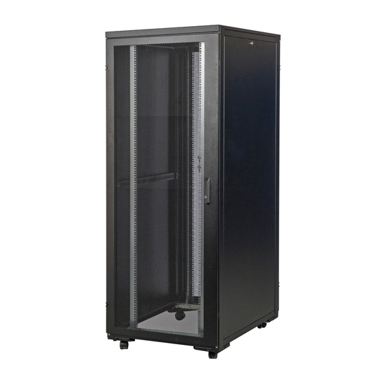
Section 1. Overview This document outlines the recommended practices for assembling and installing the RE Series server enclosure. The standard server enclosure is a high-quality design for storage of industry- standard (EIA/ECA-310), 19” rack-mount hardware, which includes servers, voice, data, networking, power protection equipment, KVM, etc., which are used in the data center rooms. -
Page 4: Component Identification
M4*8mm self-tapping screws (4pcs), the bottom plate is tightened to the enclosure with M8*25mm hexagon headed bolt. Note: Refer to the mounting instructions before installing your bottom plate. P a g e RE Series Enclosure – User Manual... -
Page 5: Packaging
CARTON B-19" RAILS & BEAM KITS Carton B Parts List Quantity Horizontal beam Vertical rail, left Cable mgmt. rail Vertical rail, right CARTON C-19" SIDE PANELS KITS Carton C Parts List Quantity Side panel assy P a g e RE Series Enclosure – User Manual... -
Page 6: Assembly
Section 4. Assembly Step 1: Connect corner brackets to the lower beams with 2 screws. Step 2: Connect each of 6 beams to the rear door with 2 screws. P a g e RE Series Enclosure – User Manual... - Page 7 Step 3: Fasten each of 6 beams in Step 2 to the front door with 2 screws Step 4: Fasten corner brackets in Step1 to the front with 2 screws P a g e RE Series Enclosure – User Manual...
- Page 8 Use M6 washers and mounting screws to secure the cable management rails, one for each side. Place M6 washers between the screws and the equipment mounting rails. P a g e RE Series Enclosure – User Manual...
- Page 9 Step 7. While holding the top cover, arrange the 2 pins near the rear of the top cover into the holes in the enclosure frame. Pull the roof panel downward until it’s close to the enclosure frame. P a g e RE Series Enclosure – User Manual...
- Page 10 Step 8. Open side panel latch by sliding it downward, then install side panels into the frame. P a g e RE Series Enclosure – User Manual...
-
Page 11: Configuration
Note: The square holes at the middle of each U-shaped vertical rail are numbered and also include a small notch to aid identification. When installing equipment, use cage nut to secure your equipment to the U-shaped vertical rail. 10 | P a g e RE Series Enclosure – User Manual... - Page 12 11 | P a g e RE Series Enclosure – User Manual...
Need help?
Do you have a question about the RE Series and is the answer not in the manual?
Questions and answers