Table of Contents
Advertisement
Quick Links
Advertisement
Table of Contents

Related Manuals for Eaton RE Series


Summary of Contents for Eaton RE Series
- Page 1 User Manual Eaton RE Series Server Enclosure RE SERIES_ RevA 3/5/2022...
-
Page 2: Table Of Contents
Eaton RE Series Rack Enclosures Important Safety Instructions ..........................2 Overview ..................................3 Available RE Series Enclosures ........................3 Feature Identification ............................... 4 Package in Flat packing ............................. 5 Main Components .............................. 5 Accessories ..............................6 Enclosure Installation---For Flat packing cabinet ..................... 7 Step 1:Triangle reinforcing plate fixed ...................... -
Page 3: Important Safety Instructions
All sections of this manual contain instructions and warnings that should be followed during the installation and use of the Eaton RE Enclosures in this manual. Failure to comply will create a risk of personal injury and property damage and may invalidate the warranty. -
Page 4: Overview
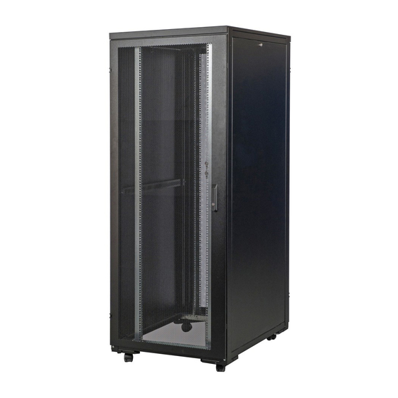
Overview This document outlines the recommended practices for assembling and installing the RE Series server enclosure. The standard server enclosure is a high-quality design for storage of industry standard (EIA/ECA-310), 19” rack-mount hardware, which includes servers, voice, data, networking, power protection equipment, KVM, etc., which are used in the data center rooms. 19" Standing Server Rack is the ultimate solution designed and engineered for demanding data center environments. -
Page 5: Feature Identification
Premier Model(Model REV426100PB is shown) Component Quantity Front vented door with lock Rear door Top cover Side panel with lock Vertical rails Horizontal beam Cable management rail Door frame Leveling feet 2" heavy duty castor Essential Model(Model REV426100EB is shown) Component Quantity Front vented door with lock... -
Page 6: Package In Flat Packing
⚫ Main Components The flat-pack concept allows shipped enclosures to reduce space which can save container and transportation costs. Note: Carton B and Carton C put in Carton A ⚫ Accessories RE SERIES_ RevA 3/5/2022... -
Page 7: Accessories
Bottom side panel Side panel bracket-Left fixing for EB series Side panel bracket Cross pan head screw GB/T818-M6-12-ZB installation Other accessories RE series Manual Allen wrench Tool PE bag L bracket Fixed on the pallet External serrated lock washer GB/T862.2-#8-ZI... -
Page 8: Enclosure Installation
Step 1:Triangle reinforcing plate fixed ⚫ Connect triangle reinforcing plate to the bottom horizontal beams by 8pcs GB/T6560-M5-10-ZI (Cross pan head self-drilling screw)【S1 accessories】. Horizontal beams 2pcs Triangle reinforcing plate-Right 2pcs Triangle reinforcing plate-Left 2pcs Step 2: Horizontal beams fixed to the rear door frame ⚫... -
Page 9: Step 3: Horizontal Beams Fixed To The Front Door Frame
Step 3: Horizontal beams fixed to the front door frame ⚫ Fixed the each horizontal beam to the rear door frame with 2pcs GB/T70.2-M6-12-SUS(Allen flat round head screw)【S2 in accessories】NOTE: 4pcs horizontal beams for EB series cabinet and 6pcs horizontal beams for PB series(Same way with step 2) Step 4: Fixed the triangle reinforcing plate to the both front and rear door frame ⚫... -
Page 10: Step 5: Fixed 2Pcs Cable Management Rails To The Horizontal Beams
Step 5: Fixed 2pcs cable management rails to the horizontal beams ⚫ Hang on the cable management rails to the horizontal beams by the back ring.Then fixed the cable tray by GB/T6560-M4-8-ZB(Full thread) Cross pan head self-drilling screw)【S3 in accessories】 Hole for screws fixing Back ring Note: 12pcs screws for PB series and 8pcs screws for EB series... -
Page 11: Step 6: Fixed 4Pcs Vertical Rails To The Horizontal Beams
Step 6: Fixed 4pcs vertical rails to the horizontal beams ⚫ Hang on the vertical rails to the horizontal beams by the back ring.Then fixed the cable tray by GB/T6560-M4-8-ZB(Full thread) Cross pan head self-drilling screw)【S3 in accessories】 Hole for screws fixing Back ring Note: 24 pcs screws for PB series and 16pcs screws for EB series ( Washer... -
Page 12: Step 7: Fixed The Top Cover
Step 7: Fixed the top cover ⚫ While holding the top cover,arrange the 2 pins near the rear of the top cover into the holes in the enclosure frame.Pull the roof panel downward until it’s close to the enclosure frame. Step 8: Side panel installation ⚫... - Page 13 Option 2. For EB series 1. Side panel bracket installation: Fix the side panel bracket to the frame by GB/T818-M6-12-ZB (Cross pan head screw) in accessories】2pcs 【S5 screws for each bracket and 8pcs for each enclosure. 2. Put the side panel without latch at the bottom (slide from top of the side panel bracket and hang on the bracket).The fixed the top side panel same as that for PB series.
-
Page 14: Enclosure Installation--For Build Up Packing Cabinet
Remove the heavy plastic bag surrounding the enclosure. Examine the enclosure for any damage or loose parts. Confirm that all parts are present. If anything is missing or damaged, contact Eaton for assistance. Do not attempt to use the enclosure if it has been damaged. -
Page 15: Placement
Open the enclosure's doors directly and locate the 2 shipping brackets that attach the enclosure to the shipping pallet. The brackets are located inside or outside the enclosure. Note: The keys are in the accessories box. Use a 13 mm open-end wrench to remove the shipping brackets. Be extremely careful, as the enclosure could shift unexpectedly after bracket removal. -
Page 16: Leveling
Leveling WARNING: Level the enclosure before attempting to install equipment. The casters are not designed to provide long-term support for the enclosure. Use the levelers to provide long-term support. Install the enclosure in a structurally sound area with a level floor that is able to bear the weight of the enclosure, all equipment that will be installed in the enclosure and any other enclosures and/or equipment that will be installed nearby. -
Page 17: Enclosure Configuration
Adding or Removing Front and Rear Doors WARNING: Do not attempt to add or remove doors without assistance. Removing Door Disconnect the door's ground wire. Open the door until it is perpendicular (90 degrees) to the front of the enclosure. Lift the door from the hinges and remove it from the enclosure. - Page 18 Reversing Front Door (continued) Remove the screw and washer from the rear of the door handle and remove the latching mechanism. Rotate the latch washer counter-clockwise 90 degrees and reverse the latch so it points in the opposite direction, then use the screw and washer to re-attach the latch to the rear of the door handle.
-
Page 19: Adding Or Removing Roof Panel
Adding or Removing Roof Panel WARNING: Do not attempt to use the roof panel for weight-bearing purposes other than those explicitly described and approved by Eaton. Do not attempt to add or remove the roof panel without assistance. Removing Roof Panel Pull the 2 pins near the rear of the roof panel. -
Page 20: Adjusting Mounting Rails And Cable Management Rails
Adding or Removing Side Panels (continued) Lift the panel away from the brace that supports it. To Reinstall Side Panel, Reverse Steps 1-3 Adjusting Mounting Rails and Cable Management Rails WARNING: Do not attempt to adjust rails without assistance. Do not attempt to adjust rails while equipment is installed in the enclosure. Do not attempt to use rails without screws installed (6 per rail). -
Page 21: Combining (Baying) Enclosures
Combining (Baying) Enclosures WARNING: Combining enclosures is not a substitute for stabilizing the enclosures. Each enclosure in a bay of combined enclosures requires the same stabilizing measures as a standalone enclosure. Arrange the enclosures in the correct position for baying. Each enclosure includes 4 baying brackets that correspond to baying connection points the adjoining enclosure. -
Page 22: Installing Or Removing Cage Nuts
Installing or Removing Cage Nuts WARNING: The flanges of the cage nuts should engage the sides of the square opening in the rail, not the top and bottom. Follow the instructions in your equipment documentation to ensure proper installation of your equipment. Installing Cage Nuts Locate the numbered square openings in the mounting rails where you plan to install your equipment. -
Page 23: Storage And Service
Eaton or an authorized Eaton service center is not covered under warranty. Products shipped to Eaton or an authorized Eaton service center must have transportation charges prepaid. Mark the RMA number on the outside of the package. If the product is within its warranty period, enclose a copy of your sales receipt.
Need help?
Do you have a question about the RE Series and is the answer not in the manual?
Questions and answers