Austroflamm Scotty Duo Operating Manual
Hide thumbs
Also See for Scotty Duo:
- Operating manual (272 pages) ,
- User instructions (116 pages) ,
- Assembly instructions manual (60 pages)
Table of Contents
Advertisement
Quick Links
Advertisement
Table of Contents

Related Manuals for Austroflamm Scotty Duo


Summary of Contents for Austroflamm Scotty Duo
- Page 1 Operating manual Scotty Duo www.austroflamm.com...
- Page 2 Tel: +43 (0) 7249 / 46 443 www.austroflamm.com info@austroflamm.com Edited by: Olivera Stojanovic Illustrations: Konstruktion Text: Technical department (Austroflamm) Copyright All Rights reserved. The contents of these instructions may be reproduced or distributed only with the consent of the publisher! Printing, spelling and typographical errors reserved.
-
Page 3: Table Of Contents
Operating manual Scotty Duo Contents Contents General information ............................Link to operating manual........................Copyright.............................. Purpose of the manual ............................Storing the manual ..........................Structure of the manual........................Representations used.......................... Version control............................. Abbreviations ............................Safety ..................................10 Importance of the safety instructions ....................10 Warning of sources of danger ...................... - Page 4 Contents Operating manual Scotty Duo 10.2 Functional diagram of your hybrid stove..................51 10.3 Operating modes ..........................52 10.3.1 Pellet operation............................ 52 10.3.2 Log operation............................52 11 Operation................................55 11.1 Operation using APP and Smartphone .................... 55 11.2 Operation using IR remote control ....................55 11.3...
- Page 5 Operating manual Scotty Duo Contents 15.1 List of alarms and errors........................73 15.2 Resetting warnings and errors ......................74 15.3 Safety temperature limiter........................74 16 Electrical connection diagram .......................... 75 16.1 Model with permanently running screw motor ................75 17 Dismantling................................80 18 Spare parts................................
-
Page 6: General Information
1 | General information Operating manual Scotty Duo General information You have decided in favour of an Austroflamm hybrid stove. Congratulations on your decision and thank you for your trust. Correct operation and care are essential for trouble-free operation and long service life. -
Page 7: Copyright
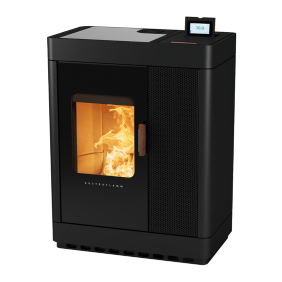
Operating manual Scotty Duo 1 | General information Fig. 1: Scotty Duo Copyright All Rights reserved. The contents of these instructions may be reproduced or distributed only with the consent of the publisher! Printing, spelling and typographical errors reserved. -
Page 8: Purpose Of The Manual
2 | Purpose of the manual Operating manual Scotty Duo Purpose of the manual This manual is a component part of the hybrid stove and is intended to contribute to the hybrid stove being safely installed and maintained. Please read this manual before using the stove for the first time. -
Page 9: Abbreviations
Operating manual Scotty Duo 2 | Purpose of the manual Abbreviations Abbreviation Meaning Heat Memory System... -
Page 10: Safety
• All dimensions in this manual are given in mm. • The initial commissioning of the hybrid stove must only be carried out by authorised Austroflamm service partners. • Your hybrid stove is not suitable for use as a ladder or a stand. - Page 11 Operating manual Scotty Duo 3 | Safety • Please alert children to these dangers, and keep them away from the hybrid stove when it is oper- ating. • No rubbish (of any kind) or residual materials may be burnt in the hybrid stove. Only the recom- mended fuels may be burnt.
-
Page 12: Safety Distances
3 | Safety Operating manual Scotty Duo 3.2.2 Safety distances When setting up in the room the following safety distances to combustible materials (minimum distances - see also nameplate) must be adhered to. • a) 700 mm (at the front in the radiation area of the door) •... -
Page 13: Product Overview
4 | Product overview Product overview Intended use The Austroflamm hybrid stove described in this manual is manufactured and tested as a type A1 self- closing appliance under EN test EN 13240. NOTICE Operation is only permitted with the door shut, ash pan locked and hopper lid closed. -
Page 14: Dimensions
4 | Product overview Operating manual Scotty Duo 4.2.2 Dimensions 1731 1664 1147 1018 1018 564.5 447.5 Fig. 4: Scotty Duo dimensions 1 Combustion air access rear/bottom 2 Air module outlet 3 Flue outlet... -
Page 15: Positioning Of The Nameplate
Operating manual Scotty Duo 4 | Product overview 4.2.3 Positioning of the nameplate The nameplate of your stove is located on the inside of the hopper lid. Fig. 5: Nameplate You can find a copy of the nameplate on the back of this manual. -
Page 16: Technical Data
5 | Technical data Operating manual Scotty Duo Technical data Technical data under Directive (EU) 2015/1185 and del. as per Regulation (EN) 2015/1186 Contact details for the manufacturer or their authorized representative Manufacturer: Austroflamm GmbH Contact: Address: Austroflamm-Platz 1 4631 Krenglbach... - Page 17 Operating manual Scotty Duo 5 | Technical data Lignite briquettes Peat briquettes Briquettes made from a mixture of fossil fuels Other fossil fuels Briquettes made from a mixture of biomass and fossil fuels Other mixture of biomass and solid fuels (*) PM = dust, OGC = organic gaseous connections, CO = carbon monoxide, NOx = nitrogen oxide (**) Only required when using correction factors F(2) or F(3).
-
Page 18: General Specifications
5 | Technical data Operating manual Scotty Duo Specification mg/m³ for heated filter method (in compliance with Annexe III, number 4, letter a, sec- tion i, point 1) or g/kg for measurement in dilution tunnel (in compliance with Annexe III, number 4, let- ter a, section i, point 2 and 3.) - Page 19 Operating manual Scotty Duo 5 | Technical data Safety distances to combustible materials, front [mm] Safety distances to combustible materials, side [mm] Safety distances to combustible materials, back [mm]...
-
Page 20: Transport, Handling And Storage
6 | Transport, handling and storage Operating manual Scotty Duo Transport, handling and storage Transport Immediately checked the goods delivered for complete- ness and damage in transit. Before installing the hybrid stove, check that all movable parts are working. Any defects before the installation of the hybrid stove must be reported. -
Page 21: Requirements At The Installation Location
Operating manual Scotty Duo 7 | Requirements at the installation location Requirements at the installation location Requirements to be met by the installation room Your hybrid stove must not be set up in: • spaces in which the required combustion air supply is not guaranteed. -
Page 22: Fuel Material/-Quantity
8 | Fuel material/-quantity Operating manual Scotty Duo Fuel material/-quantity Fuel material Pellets Poor pellet quality will cause significant residues in the hy- brid stove when burnt. We therefore urge the use of pellets that have no artificial binding agents. That way only a small unburnt residue is left. -
Page 23: Fuel Quantity
Operating manual Scotty Duo 8 | Fuel material/-quantity Fuel Only burn the recommended fuel. Fuel quantity Maximum fuel quantity Every hybrid stove is designed for a maximum fuel quantity: see Technical Data [}on page 16] section. Larger fuel quantities lead to overheating and damage to the hybrid stove! -
Page 24: Installation
9 | Installation Operating manual Scotty Duo Installation Installation must only be carried out by an authorized specialist company. Before installing the hybrid stove, check that all movable parts are working. Any defects before the in- stallation of the hybrid stove must be reported. - Page 25 Operating manual Scotty Duo 9 | Installation Item Item Article no. Cladding right 729868 Silicon metal buffer 772099 1) Check the distance of 111 mm, if necessary adjusting the door before continuing. Fig. 12: Checking the distance 2) Remove the grate motor (M5/SW8).
- Page 26 9 | Installation Operating manual Scotty Duo 6) Undoing both screws (1) (TX25) and removing the top cover (2) Fig. 16: Undoing the screws - removing the cover 7) Install grate motor (M5/ SW8). Fig. 17: Installing the grate motor 8) Remove all the silicon metal buffers (1).
- Page 27 Operating manual Scotty Duo 9 | Installation 12) Use the adjusting screws (5) (TX10) to align the clad- ding cover and the hopper lid. 13) Mount and tighten the four nuts (6) (M5/SW8). Fig. 19: Aligning and tightening Fig. 20: Result...
- Page 28 9 | Installation Operating manual Scotty Duo 14) Position the cladding right as illustrated on the stove body. 15) Insert hinge pins (2). 16) Align cladding right to the stove body by adjusting the hinges (3+4). Fig. 21: Mounting and aligning the cladding right 17) Open door (1).
- Page 29 Operating manual Scotty Duo 9 | Installation 21) Loosely screw in screws (1) (M5/SW8). 22) Using the adjusting screws (2) (TX10), align the clad- ding right on the stove body. 23) Tighten the screws (1) (M5/SW8). Fig. 24: Aligning cladding right Fig. 25: Cladding aligned...
- Page 30 9 | Installation Operating manual Scotty Duo 27) Position the cladding left as illustrated on the stove body. 28) Inserting the four hinge pins (2) 29) Align cladding left to the stove body by adjusting the hinges (3+4). 30) Close cladding left.
- Page 31 Operating manual Scotty Duo 9 | Installation 31) Open door (1). 32) Loosely screw in both the screws (2) (M5/SW8). 33) Using the adjusting screws (TX10), align the cladding left on the stove body. 34) Tighten both the screws (2) (M5/SW8).
- Page 32 9 | Installation Operating manual Scotty Duo 35) Attach top cover and fasten the two screws (TX25). Fig. 30: Attaching cover Fig. 31: Fastening the screws (TX25) 36) Mount the hopper trough (1) and fasten with the two nuts (2) (M5/SW8). 37) Attach silicon metal buffers (3) (M6/SW10) and align the hopper cover.
-
Page 33: Mounting The Ceramic Cladding
Operating manual Scotty Duo 9 | Installation 41) Inserting convection lamella left and fastening with the two nuts (M6/SW10) 42) Mounting and correctly aligning the silicon metal buf- fers (M6/SW10) Fig. 34: Attaching and fastening the silicon buffers 43) Insert window inlay cover. - Page 34 9 | Installation Operating manual Scotty Duo Frame 7:50 Fig. 37: Frame overview Item Item Item no. Fillister head screws with hexagon head M6x50 ISO7380 718043-92 Cheesehead bolts with socket head (very low head) M5x8 718045-92 1 BN1206 Grub screw with hex and eyebolt M5x8 DIN916...
- Page 35 Operating manual Scotty Duo 9 | Installation Convection lamella, left Item Item Item no. Convection lamella installed on the left 729211-29 Convection lamella, right Item Item Item no. Convection lamella installed on the right 729212-29...
- Page 36 9 | Installation Operating manual Scotty Duo 1) Check the distance of 111 mm, if necessary adjusting the door before continuing. 111 mm Fig. 38: Checking the distance 2) Remove the grate motor (M5/SW8 and T25). Fig. 39: Removing the grate motor 3) Mount lower ceramic frame (position 1, 2, 3).
- Page 37 Operating manual Scotty Duo 9 | Installation 6) Align the base with the four adjusting screws (2) (TX10) on the stove. Fig. 42: Aligning the base 7) Mount and tighten four nuts (3) (M5/SW8). Fig. 43: Mounting and tightening the nuts 8) Install grate motor (M5/SW8 and TX25).
- Page 38 9 | Installation Operating manual Scotty Duo 10) Mount upper ceramic frame (position 4, 5, 6, 7). Fig. 46: Mounting the upper ceramic frame 11) Align and tighten eight screws (Allen key 3). Fig. 47: Aligning the eight screws 12) Mount screws, nuts and silicon metal buffer.
- Page 39 Operating manual Scotty Duo 9 | Installation 13) Check and adjust the distance (1) to 13 mm (M5/ SW8). 13 mm Fig. 50: Distance to 13 mm 14) Lift the hopper lid (2) and use a suitable tool to keep it in the half-open position.
- Page 40 9 | Installation Operating manual Scotty Duo 18) Use the adjusting screws (TX10) to align the upper ceramic frame and the hopper cover (5). Fig. 53: Aligning the upper ceramic frame 19) Position frame on the stove. 20) Insert hinge pins (2).
- Page 41 Operating manual Scotty Duo 9 | Installation 23) Mount four screws (1) and four nuts (2) but do not fully tighten them. ð These screws are only tightened after the ceramic cladding has been mounted and correctly posi- tioned. 24) Repeat the previous step in order to mount the screws and nuts on the frame on the other side.
- Page 42 9 | Installation Operating manual Scotty Duo 27) Open door. Fig. 58: Opening the door 28) Undo screws (M5/SW8). Fig. 59: Undoing the screws 29) Remove cladding front (3). Fig. 60: Removing the front cladding...
- Page 43 Operating manual Scotty Duo 9 | Installation 30) Insert the screws (1) (M5/SW8). 31) Using the adjusting screws (2) (TX10) align the ceramic tiles on the stove so as to achieve the result shown. 32) Fix the ceramic tile with two screws (1) (M5/SW8).
- Page 44 9 | Installation Operating manual Scotty Duo 33) Open door. Fig. 63: Opening the door 34) Put on the front cladding and loosely turn in the screws. Fig. 64: Placing the front cladding on 35) Align cladding with adjusting screws (3) (TX10) and tighten the screw (2).
- Page 45 Operating manual Scotty Duo 9 | Installation 36) Open door and fix the left ceramic tile with two screws (1) (M5/SW8). Fig. 66: Fixing the left ceramic tile 37) Align ceramic tile as shown here. Fig. 67: Ceramic tile aligned...
- Page 46 9 | Installation Operating manual Scotty Duo 38) Mount the hopper trough (1) and fasten with the two nuts (2) (M5/SW8). 39) Attach silicon metal buffer (3) (M6/SW10) and align the hopper cover. 40) Check the functioning of the hopper lid switch (aud- ible click sound when opening/closing).
- Page 47 Operating manual Scotty Duo 9 | Installation 43) Attach top cover (1) and fasten the two screws (2) (TX25). Fig. 71: Attaching cover 44) Insert convection lamella (1) left and mount with the two nuts (2)(M6/SW10). 45) Mount and correctly align the silicon metal (3) buffer (M6/SW10).
-
Page 48: Mounting The Firebox Lining (Keramott)
9 | Installation Operating manual Scotty Duo 9.2.3 Mounting the firebox lining (Keramott) Numbering = installation sequence... -
Page 49: Operation
Operating manual Scotty Duo 10 | Operation Operation 10.1 Requirements for operation External combustion air supply Every combustion requires oxygen. This is drawn from the environment of the heating appliance. In modern buildings the outside covering is very thick. Therefore there is an insufficient flow of fresh combustion air. - Page 50 10 | Operation Operating manual Scotty Duo • The horizontal length of the exhaust pipe must not exceed 2.5 m. • A maximum number of 3x90° bends must not be exceeded. Each bend must have a cleaning aper- ture. • The chimney must be resistant to condensation.
-
Page 51: Functional Diagram Of Your Hybrid Stove
Operating manual Scotty Duo 10 | Operation 10.2 Functional diagram of your hybrid stove Fig. 76: Functional diagram... -
Page 52: Operating Modes
10 | Operation Operating manual Scotty Duo 10.3 Operating modes 10.3.1 Pellet operation Automatic ignition The stove can be started with the start/stop button on the status display or heat output display. As an option it can be started via IR remote control or via the app. - Page 53 Operating manual Scotty Duo 10 | Operation Hybrid start Hybrid start is used for igniting the logvia pellet ignition. In hybrid start, pellets are fed in and the damper doors for the supply of combustion air are opened. This ensures the op- timum burning of the inserted log.
- Page 54 10 | Operation Operating manual Scotty Duo Log operation In this operating status the stove automatically controls the combustion of the log. Depending on the output set the stove will try to maintain a specific firebox temperature. If this cannot be achieved, in the background (not visible on the display) the next lower Fig. 82: Log operation...
-
Page 55: Operation
11.1 Operation using APP and Smartphone Please refer to the manual for your WLAN module for in- structions on installing and setting up the data connection, or follow the installation instructions for the Austroflamm PelletControl app. Download the required “Austroflamm PelletControl” app here and then start: Fig. 83: Apple iOS QR code... -
Page 56: Operation Using Touch Display
11 | Operation Operating manual Scotty Duo 11.3 Operation using touch display 11.3.1 Display - room temperature display, various functions You can switch to the relevant setting or function by press- ing the corresponding symbol. The desired target temperature can be set between 5°C and 40 °C by pressing the buttons in 0.2°C incre-... -
Page 57: Display - Status Display
11.4.1 Function - air distribution fan An air distribution module is available as an option for Scotty Duo. It can be used to heat an extra room via warm air. The warm air is sucked from the back wall of the firebox. -
Page 58: Function - Filling Level Indicator
11 | Operation Operating manual Scotty Duo On some appliance models, connection via the floor is also possible. A pipe or hose of Ø 125 mm must be used for connecting the external combustion air supply. The length of the pipe or hose should be no longer than 5 m. This supply line must have no more than three bends. -
Page 59: Function - Setting Timers And Heating Times
Operating manual Scotty Duo 11 | Operation 11.4.4 Function - setting timers and heating times Pressing the “TIMERS” button in the heating output display takes you into the “Heating times” menu. Enable heating times by pressing “ON” in the top right corner of the display. - Page 60 11 | Operation Operating manual Scotty Duo 00 01 02 03 04 05 06 07 08 09 10 11 12 13 14 15 16 17 18 19 20 21 22 23 18°C 22°C 18°C 22°C 18°C 18°C 22°C 18°C 18°C 22°C...
-
Page 61: Adjustments
Operating manual Scotty Duo 12 | Adjustments Adjustments 12.1 Display - settings Pressing the “SET” button on the menu list Takes you to the “Settings” menu. You can scroll the list up and down. Pressing the desired menu item switches you to that func- tion. -
Page 62: Menu Item - Fuel
12 | Adjustments Operating manual Scotty Duo 12.3 Menu item - fuel This submenu can be used to disable “filling level indic- ator”. When deactivated the bar on the display disappears. There will be no warning when the filling level is low. -
Page 63: Menu Item - Anti-Frost
Operating manual Scotty Duo 12 | Adjustments 12.6 Menu item - anti-frost The anti-frost menu is used to automatically start the stove at a specified temperature. The menu only functions when the timer function is enabled. 12.7 Menu item - display options The following display options are available. -
Page 64: Menu Item - Volume
The service must be carried out by an authorised Austro- flamm service engineer. Fig. 106: Service due 12.12 Menu item - service menu This menu is reserved for the Austroflamm service engineer. 12.13 Menu item - display lock You have the option to restrict functions on the display (“Child safety”). -
Page 65: Menu Item - Language
Operating manual Scotty Duo 12 | Adjustments 12.14 Menu item - Language Choose the desired language on your control panel. Fig. 108: Language 12.15 Menu item - Info Hardware and software versions of the individual compon- ents are displayed here. In case of servicing, please have the •... -
Page 66: Setting The Firebox Door Closing Pressure
12 | Adjustments Operating manual Scotty Duo 12.18 Setting the firebox door closing pressure 1) Open the door. Fig. 112: Opening the door 2) The tension spring can be adjusted with a screwdriver and a fork spanner. Fig. 113: Adjusting the tension spring... -
Page 67: Adjusting The Ash Box Door
Operating manual Scotty Duo 12 | Adjustments 12.19 Adjusting the ash box door 1) Open the door. Fig. 114: Opening the door 2) The ash box door can be adjusted at the screws to the relevant position. Fig. 115: Adjusting the ash box door 12.20 Adjusting the firebox door... - Page 68 12 | Adjustments Operating manual Scotty Duo 2) The hinges (1) can be adjusted with the marked screws A + B. ð A: left/right ð B: forwards/backwards 3) The snap (2) can be adjusted forwards and backwards at the springs.
-
Page 69: Commissioning
4) Insert power cable and set tumbler switch on the back of the hybrid stove to “I”. ð The Austroflamm logo will now appear on the display. ð This is followed by the main operating level with temperature displays and hopper level. -
Page 70: Maintenance
14 | Maintenance Operating manual Scotty Duo Maintenance 14.1 Intervals Cleaning- and maintenance intervals depend on the operating hours and connection situation. Cleaning the viewing window as necessary Visual inspection of riddling grate, remove adhering de- Every 2-3 operating days... -
Page 71: Cleaning The Exhaust Gas Pipes
Operating manual Scotty Duo 14 | Maintenance 14.3 Cleaning the exhaust gas pipes... -
Page 72: Changing The Storage Battery
14 | Maintenance Operating manual Scotty Duo 14.4 Changing the storage battery A type CR2032 storage battery is located in the controls. The control unit uses this storage battery to store certain data, e.g. time, date, and heating times, even during a power failure or if cut off from the mains. -
Page 73: Alarms And Error Messages
Operating manual Scotty Duo 15 | Alarms and error messages Alarms and error messages 15.1 List of alarms and errors Alarms are displayed on the control panel in yellow. When an alarm is displayed the hybrid stove can continue to be used. Errors are displayed in red. When errors are displayed the hybrid stove is not ready for operation. -
Page 74: Resetting Warnings And Errors
15 | Alarms and error messages Operating manual Scotty Duo 15.2 Resetting warnings and errors In the event of a warning or error a yellow or red message with the description is displayed. 1) To close the warning display, tap ð... -
Page 75: Electrical Connection Diagram
16 | Electrical connection diagram Electrical connection diagram 16.1 Model with permanently running screw motor NOTICE Repairs to your hybrid stove must only be carried out by authorised Austroflamm engineers. Electrical connection diagram - overview Door contact switch PWM DC changeover... - Page 76 16 | Electrical connection diagram Operating manual Scotty Duo Ceramic ignition exhaust gas fan Safety temperature limiter Hopper lid safety switch Grate positioning Damper motor Grate motor Central earthing point OPT1 External thermostat OPT2 Air distribution module See detailed electric connection diagram...
- Page 77 Operating manual Scotty Duo 16 | Electrical connection diagram Electric connection diagram, detailed - screw motor Electric connection diagram, detailed - grate motor...
- Page 78 16 | Electrical connection diagram Operating manual Scotty Duo Electric connection diagram, detailed - damper motor...
- Page 79 Operating manual Scotty Duo 16 | Electrical connection diagram Electric connection diagram, detailed - data cable splitter...
-
Page 80: Dismantling
17 | Dismantling Operating manual Scotty Duo Dismantling For correct uninstallation and dismantling of the hybrid stove, contact your Austroflamm specialist dealer. -
Page 81: Spare Parts
Operating manual Scotty Duo 18 | Spare parts Spare parts Scotty Duo accessories Item Item Item no. Elbow piece 130 - set 620066 Air distribution module (ADM) 805003 SCOTTY DUO 812001 VK ceramic, complete 812002-XX VK steel, complete 812003-29... - Page 82 18 | Spare parts Operating manual Scotty Duo Keramott Item Item Item no. Elbow 2 728661 Floor, front 728662K Firestone, left 728656-B Firestone, right 728656-A Floor, rear 728654 Floor, left 728651 Floor, right 728653 Floor, middle 728652 side wall, left...
- Page 83 Operating manual Scotty Duo 18 | Spare parts right cladding front Item Item Item no. Taptite counter-sunk head bolt M5X10 DIN7500M 718481-92 Hex M5 HUT/FEF 3 718769-93 Hexagon nut with flange, M5 DIN6923 723916-92 S VK front right 2 729335-29...
- Page 84 18 | Spare parts Operating manual Scotty Duo Convection lamella, left Item Item Item no. Convection lamella installed on the left 729211-29 Convection lamella, right Item Item Item no. Convection lamella installed on the right 729212-29...
-
Page 85: Disposal
(Keramott), ceramic, sensors and baffle plates and dispose of them in the household waste. NOTICE For correct uninstallation and dismantling of the hybrid stove, contact your Austroflamm specialist dealer. Electric and electronic components Remove the electric and electronic components from the appliance by dismounting them. - Page 86 19 | Disposal Operating manual Scotty Duo Handles and decorative elements made of metal If present, disassemble or remove handles and decorative elements made of metal and dispose of as metal scrap. Local disposal options must be observed.
-
Page 87: Warranty And Guarantee
For the replaceability of the warranty case the start-up log must be received by Austroflamm within one month at the latest of the initial commis- sioning. In order to make a claim on the warranty, repairs to your hybrid stove insert must only be carried out by a service engineer authorized by Austroflamm. -
Page 88: Data Processing
If you consent to the appropriate handling of your personal data for the following purposes, please tick this box. o I hereby agree that Austroflamm GmbH and AUSTROFLAMM Service GmbH & Co KG may send me service reminders and offers on other products from Austroflamm GmbH for the purposes of advert- ising via E-Mail/ SMS/ telephone. -
Page 89: Start Up Log
Operating manual Scotty Duo 22 | Start up log Start up log Operator / Customer Dealer / Engineer Name Company Street Street Town and postal code Town and postal code Telephone Telephone Email Email Pellet stove Model Control software version... -
Page 90: Service Report
23 | Service Report Operating manual Scotty Duo Service Report Date Technicians Notes Work carried out, replacement parts installed... - Page 91 Operating manual Scotty Duo 23 | Service Report Date Technicians Notes Work carried out, replacement parts installed...
- Page 92 Notizen / notes / appunti / remarques...
- Page 93 Notizen / notes / appunti / remarques...
- Page 94 Vollständigkeit / completeness / completo / complet Geprüft von / checked by / controlled da / contrôlé par ____________________________________________________ Datum / date / data / date ____________________________________________________ AUSTROFLAMM GMBH Austroflamm-Platz 1 A- 4631 Krenglbach Tel: +43 (0) 7249 / 46 443 www.austroflamm.com info@austroflamm.com...
Need help?
Do you have a question about the Scotty Duo and is the answer not in the manual?
Questions and answers