E+E Elektronik EE610 User Manual
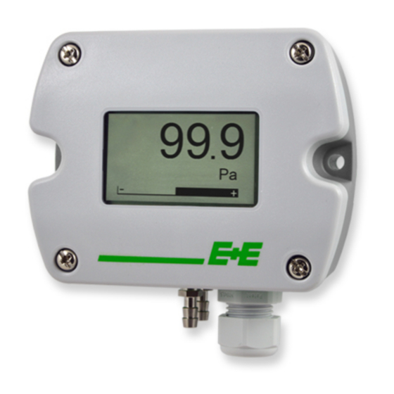
Low differential pressure sensor
Hide thumbs
Also See for EE610:
- User manual (20 pages) ,
- Quick manual (2 pages) ,
- User manual (28 pages)

Subscribe to Our Youtube Channel
Related Manuals for E+E Elektronik EE610


Summary of Contents for E+E Elektronik EE610
- Page 1 User Manual EE610 Low Differential Pressure Sensor BA_EE610_e // v1.1 // technical data are subject to change...
- Page 2 E+E Elektronik Ges.m.b.H. accept warranty and liability claims neither upon this publication nor in case of improper treatment of the described products. The document may contain technical inaccuracies and typographical errors. The content will be revised and updated on aregular basis. The described products can be improved and changed at any time without prior notice.
-
Page 3: Table Of Contents
4.2.6 Reading example ...............................10 Installation ............................11 Pressure connection ............................11 Maintenance and service ........................12 Cleaning ..............................12 Repairs ................................12 Readjustment of EE610 ..........................13 6.3.1 Zero Point Adjustment ............................13 6.3.2 Span Point Adjustment ............................13 6.3.3 Return to Factory Adjustment ..........................14 User Interface ............................14 LED indication ............................14... -
Page 4: General
This symbol indicates safety information. It is essential that all safety information is strictly observed. Failure to comply with this information can lead to personal injuries or damage to property. E+E Elektronik® assumes no liability if this happens. This symbol indicates instructions. -
Page 5: Environmental Aspects
Environmental aspects Products from E+E Elektronik® are developed and manufactured observing of all relevant requirements with respect to environment protection. Please observe local regulations for the device disposal. For disposal, the individual components of the device must be separated according to local recycling regulations. -
Page 6: Product Description
Analogue version (A7) Digital version (J3) 15...35 V DC power supply 24 V AC ±20 % 24 V AC ±20 % 15...35 V DC A (=D+) RS485 B (=D-) Fig. 3 Connection diagram User Manual EE610 Low Differential Pressure Sensor... -
Page 7: Setup
Setup Analogue version Each EE610 leaves the E+E factory with the default setup (all switches on „0“): • Measurement range: ±100 Pa • Response time: 50 ms • Display unit: • Backlight display: • Output signals: 0-10 V and 4-20 mA EE610 is fully configurable. -
Page 8: Select The Output Signal With S8
Indication of Δp > scale value high, + 5 % of span Digital version The EE610 is ready to use and does not require any configuration by the user. The factory setup of EE610 corresponds to the type number ordered. For ordering guide please see data sheet at www.epluse.com/ee610. -
Page 9: Ee-Pcs Product Configuration Software
BACnet Protocol settings The recommended settings for multiple devices in a BACnet MS/TP network are 38400, 8, None, 1. The EE610 PICS (Product Implementation Conformance Statement) is available on the website at www.epluse.com/ee610. ID address, baud rate can be set via: 1. -
Page 10: Modbus Register Map
Reading example Example of MODBUS RTU command for reading the differential pressure (float value) Δp = -32,260543 Pa from the register 0x4BE: Device EE610; slave ID 44 [2C in Hex] Reference document, chapter 6.3: www.modbus.org/docs/Modbus_Application_Protocol_V1_1b.pdf Request [Hex]: 2C 04 04 BE 00 02 16 A2... -
Page 11: Installation
(Register 1 - Lo) -32,260543 Installation • Mount the EE610 onto a vertical, smooth surface. • Important: The pressure connection nipples must point downwards. • Avoid installation close to heaters and sources of strong electromagnetic interference. • Insert the cable for supply voltage and output signal through the cable gland and connect it to the spring terminals according to the wiring diagram („Fig. -
Page 12: Maintenance And Service
Use a Ø 7.5 mm drill. • Connect the pressure hose (included in the scope of supply) first to the EE610 and then to the nipples at the duct. Route the pressure hose for avoiding sharp bends which might lead to the hose obstruction („Fig. -
Page 13: Readjustment Of Ee610
Readjustment of EE610 A periodical readjustment of EE610 might be required by the regulations of certain industries or by the need of best long-term measurement accuracy. The zero point and the span point can be adjusted with push buttons on the EE610 electronics board. -
Page 14: Return To Factory Adjustment
User Interface LED indication Green LED Red LED flashing (1 s interval) = EE610 operates normally, the flashing (1 s interval) = the measured data is out of measured data is within the the selected range (overload selected measuring range... -
Page 15: Technical Data
: 50 ms; display unit: Pa; display backlight: on; analogue outputs: 0-10 V and 4-20 mA. Other ranges upon request. 2) Factory setup RS485: response time t : 500 ms; display unit: Pa; display backlight: on 3) Voltage and current output signals available simultaneously at the spring loaded terminals. User Manual EE610 Low Differential Pressure Sensor... - Page 16 HEADQUARTERS SUBSIDIARIES E+E Elektronik Ges.m.b.H. E+E Elektronik Germany E+E Elektronik France E+E Elektronik Korea Langwiesen 7 info@epluse.de info@epluse.fr Tel: +82 31 732 6050 A-4209 Engerwitzdorf Tel: +33 4 74 72 35 82 info@epluse.co.kr Office Bad Homburg Austria Tel: +49 6172 13881-0...
Need help?
Do you have a question about the EE610 and is the answer not in the manual?
Questions and answers