
Related Manuals for Casio KL-7000


Summary of Contents for Casio KL-7000
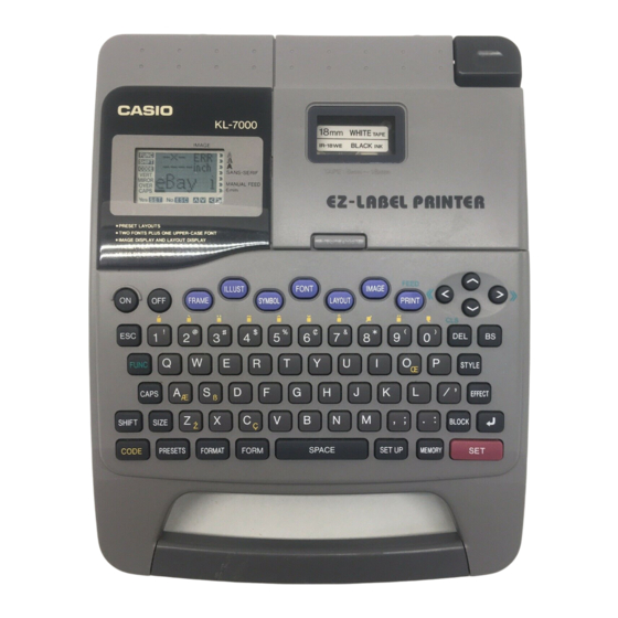
- Page 1 (without price) LABEL PRINTER KL-7000 (LX-271) MAR. 1995 KL-7000(BK) KL-7000(GY)
-
Page 2: Table Of Contents
CONTENTS SPECIFICATIONS------------------------------------------------------------------------------------------------1 CLEANING THE PRINTER HEAD AND ROLLER------------------------------------------------------2 RESET OPERATION--------------------------------------------------------------------------------------------2 BLOCK DIAGRAM-----------------------------------------------------------------------------------------------3 PRECAUTIONS---------------------------------------------------------------------------------------------------4 ADJUSTMENT-----------------------------------------------------------------------------------------------------4 MEASUREMENT--------------------------------------------------------------------------------------------------5 CIRCUIT DESCRIPTION---------------------------------------------------------------------------------------6 LSI PIN FUNCTION---------------------------------------------------------------------------------------------7 DIAGNOSTIC PROGRAM-------------------------------------------------------------------------------------9 MESSAGES--------------------------------------------------------------------------------------------------------11 DISASSEMBLY PROCEDURE-------------------------------------------------------------------------------12 SCHEMATIC DIAGRAM----------------------------------------------------------------------------------------13 PARTS LIST------------------------------------------------------------------------------------------------------18 EXPLODED VIEW-----------------------------------------------------------------------------------------------20... -
Page 3: Specifications
SPECIFICATIONS Input Keyboard layout : Typewriter (QWERTY) Character Types Alpha (English and other languages) : 151 Numbers : Symbols : Illustrations : Display Type : 48 X 32-dot liquid crystal display Number of columns : Character matrix : 16 X 16-dot Printing Type : 64-dot thermal transfer... -
Page 4: Cleaning The Printer Head And Roller
CLEANING THE PRINTER HEAD AND ROLLER 1 : Make sure to turn the power switch off. 2 : Open the tape cartridge compartment cover. 3 : Remove the tape cartridge. 4 : Use a cotton swab dipped in alcohol to clean the printer head and roller. 5 : Replace the tape cartridge and close the compartment cover. -
Page 5: Block Diagram
BLOCK DIAGRAM LCD 49 X 32 CD427-TS Comparator LCD driver LCD driver BA10339F-T1 HD44105H HD44102CH COMMON SEGMENT Chassis unit Keyboard Motor driver T6C37 BA12003 Thermal Head Reset IC RH5VL45AA-T1 VDD1 ( +5V for digital circuit) TC531001CF-15 (+12V for printer) VDD2 (+5V for RAM)) VCON Q6 / IC5... -
Page 6: Precautions
PRECAUTIONS To prevent damage of the thermal head caused by static electricity when assembling the chassis ass'y into the unit, the following steps must be followed; 1 : Turn the power switch off. 2 : Discharge the capacitor C18(2200µF) on the PCB L271-1. CN301 3 : Connect the FPC of chassis ass'y into a connector CN301 of PCB L271-2. -
Page 7: Measurement
Max. 12.24V Ibat Typ. 25 mA Turning power SW on. (Displaying) Max. 100 mA When printing "CASIO COM..." at diagnostic program Ibat Typ. 0.6A PRINT CHECK-1. (Printing) 0.7A When printing " ! " at diagnostic program PRINT CHECK-1. Min. ---- Turning power SW off and disconnecting power 15 µA... -
Page 8: Circuit Description
CIRCUIT DESCRIPTION Setting the batteries or AC adaptor (see figure 8) When setting the batteries or AC adaptor, the voltage VDD2 is always applied to RAM and CPU since Q6 and IC5 are turned on. Power on sequence (see figure 8) When the power switch is turned on, PON signal is being H (PON = VDD2). -
Page 9: Lsi Pin Function
LSI PIN FUNCTION CPU (T6C37) : LSI1 Name I / O Function Read signal for memory devices Write signal for memory devices +5V source 4~15, 17~21 A0~A11, EA12~EA16 Address bus Ground (0V) source +5V source Chip enable signal for ROM Chip enable signal for RAM RNK1 Thermal head rank setting... - Page 10 LCD driver (HD44105H) : LSI201 N a m e I / O Function 1~12, 41~60 X1~X32 LCD drive output I / O I/O pin for 2 way shift register and shift data Ground 15, 16 FS1, FS2 Select frequency 17~19 DS1~DS3 Select display duty Oscillator...
-
Page 11: Diagnostic Program
DIAGNOSTIC PROGRAM Note : Make the reset operation after RAM check, because the RAM check break the data stored in RAM. Check item Operation Display N o t e (BOOT) Press ON while pressing Main menu 0 ALL 7 VP keys, SET + RETURN + 1 RAM 2 LCD... - Page 12 Check item Operation Display N o t e KEY CHECK Press the key according to (3 KEY) what is appeared on the LCD. Press any key after last key check to return the main menu. RANK CHECK Check the rank of the thermal RANK (4 SW) head employed in the unit.
-
Page 13: Messages
MESSAGES Message Meaning Action NO DATA! There is no data stored in memory. Store some data before trying to perform this operation. NOT ENOUGH There is not enough unused memory to Reduce the size of the data you are MEMORY! perform the operation. -
Page 14: Disassembly Procedure
DISASSEMBLY PROCEDURE 1 : Remove the battery cover, batteries and ink ribbon cassette. 2 : Remove 8 screws holding the lower cabinet and take it off. (Refer to figure-11) 3 : Re-solder 6 wires from Buzzer and battery terminals. 4 : Remove 4 screws(A) holding PCB L271-1 and take out the connector CN3 on PCB L271-1. 5 : Take out FPC of chassis ass'y from PCB L271-2 and remove 2 screws(B) holding the PCB L271-2. -
Page 15: Schematic Diagram
SCHEMATIC DIAGRAM PCB L271-1 (1/2) — 13 —... - Page 16 PCB L271-1 (2/2) — 14 —...
- Page 17 PCB L271-E4(1/2) — 15 —...
- Page 18 PCB L271-E4 (2/2) — 16 —...
- Page 19 PCB L271-2 — 17 —...
-
Page 20: Parts List
EXPLODED VIEW Component — 18 —... - Page 21 Chassis ass'y Cross section of A-A Thermal Head — 19 —...
- Page 22 BK : BLACK PARTS LIST GY : GREY FOB Japan Item Code No. Parts Name Specification Q'ty N.R.Yen BK GY Unit Price PCB-1 ASS'Y 6410 7080 Adhesive tape C-L263 C413532-1 1 20 6410 7080 Adhesive tape C-L263 C413532-1 1 20 6410 7011 PC joiner L263 C413507A-1 1 10...
- Page 23 FOB Japan Item Code No. Parts Name Specification Q'ty N.R.Yen BK GY Unit Price 2795 5355 Chip resistor MCR10EZHF4870 1 20 R27~R33 2792 0831 Chip resistor MCR10EZHJ103 1 20 2792 0815 Chip resistor MCR10EZHJ221 1 20 2795 1358 Chip resistor MCR10EZHJ511 1 10 R4,R5...
- Page 24 FOB Japan Item Code No. Parts Name Specification Q'ty N.R.Yen BK GY Unit Price 6413 4660 PCB-1 ass'y A140058*1A 6410 6990 Battery spring B-L263 C413503-1 1 20 6329 7620 Battery spring A-G272 A33938-1 1 10 6393 1710 Nut B-V346 A411430-2 1 20 6413 0010 Adhesive tape D-L263AEJ C440140-1...
- Page 25 FOB Japan Item Code No. Parts Name Specification Q'ty N.R.Yen BK GY Unit Price 1908 6656 Screw (+) M2 X 4 ZMC-3 2 20 6400 9780 Head spring A-L240 A412366-1 1 20 6410 8091 Platen L263 C312242A-1 6413 4870 Tape fixing plate L271 C312239-3 0 20 6413 6570 Tape fixing plate L271BE...
- Page 26 MA0500751A...
Need help?
Do you have a question about the KL-7000 and is the answer not in the manual?
Questions and answers