Rockwell Automation Allen-Bradley Guardmaster MSR57P User Manual
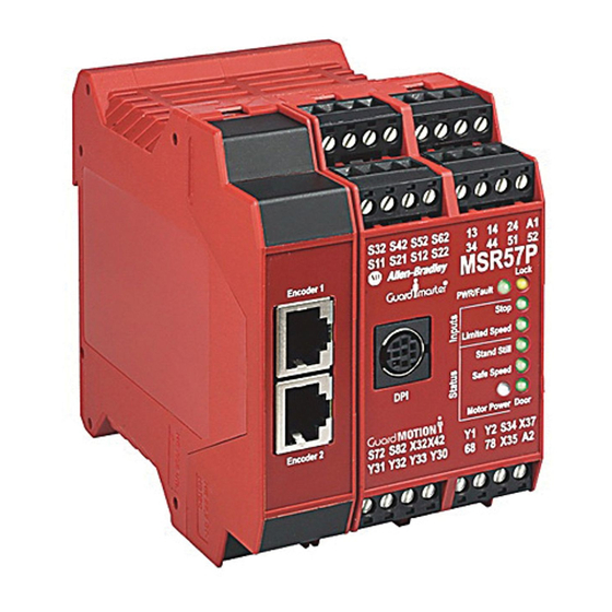
Speed monitoring safety relay
Hide thumbs
Also See for Allen-Bradley Guardmaster MSR57P:
- Release note (8 pages) ,
- User manual (20 pages) ,
- User manual (246 pages)

Subscribe to Our Youtube Channel
Related Manuals for Rockwell Automation Allen-Bradley Guardmaster MSR57P


Summary of Contents for Rockwell Automation Allen-Bradley Guardmaster MSR57P
- Page 1 MSR57P Guardmaster Speed Monitoring Safety Catalog Number 440R-S845AER-NNL User Manual Original Instructions...
- Page 2 If this equipment is used in a manner not specified by the manufacturer, the protection provided by the equipment may be impaired. In no event will Rockwell Automation, Inc. be responsible or liable for indirect or consequential damages resulting from the use or application of this equipment.
-
Page 3: Table Of Contents
Circuit Diagram ..........26 Rockwell Automation Publication 440R-UM004C-EN-P - October 2021... - Page 4 Feedback Parameter List......... 65 Rockwell Automation Publication 440R-UM004C-EN-P - October 2021...
- Page 5 SLS Status Only Wiring Examples ....... . 92 Rockwell Automation Publication 440R-UM004C-EN-P - October 2021...
- Page 6 Max Speed Group......... . . 133 Rockwell Automation Publication 440R-UM004C-EN-P - October 2021...
- Page 7 Using DriveExecutive Software........165 Rockwell Automation Publication 440R-UM004C-EN-P - October 2021...
- Page 8 Index ............177 Rockwell Automation Publication 440R-UM004C-EN-P - October 2021...
-
Page 9: About This Publication
You must also be trained and experienced in the creation, operation, and maintenance of safety systems. Conventions This manual lists configuration parameters by number, followed by the name in brackets. For example, P24 [OverSpd Response]. Rockwell Automation Publication 440R-UM004C-EN-P - October 2021... -
Page 10: Terminology
A measure of a products ability to lower the risk that a dangerous failure could occur. Safely-limited Speed — Safe Maximum Acceleration — Safe Maximum Speed — Safe Stop — State Torque Off — Rockwell Automation Publication 440R-UM004C-EN-P - October 2021... -
Page 11: Additional Resources
Industrial Automation Wiring and Grounding Guidelines, publication 1770-4.1 Provides general guidelines for installing a Rockwell Automation industrial system. Product Certifications website, rok.auto/certifications. Provides declarations of conformity, certificates, and other certification details. You can view or download publications at rok.auto/literature. - Page 12 Preface Notes: Rockwell Automation Publication 440R-UM004C-EN-P - October 2021...
-
Page 13: Safety Concept
Safe Stop. The stop button setting is not maintained through a power cycle. Do not use the stop button with an automatic reset configuration. Unintended motion could result. Rockwell Automation Publication 440R-UM004C-EN-P - October 2021... -
Page 14: Safety Category 4 Performance Definition
PL and SIL determination. Safety Configuration and Verification on page 121, for more information on the requirements for the configuration and verification of a safety-related system that contains the MSR57P speed monitoring safety relay. Rockwell Automation Publication 440R-UM004C-EN-P - October 2021... -
Page 15: Functional Proof Tests
When you cycle power, the safety relay enters the safe state for self-testing. If the self-tests pass and there is a valid configuration, the safety relay remains in the safe state until a successful request for safe speed monitoring occurs. Rockwell Automation Publication 440R-UM004C-EN-P - October 2021... -
Page 16: Safety Reaction Time
You must exercise the SS_In input at least once every 6 months. You can disable pulse tests if the connected device does not support OSSD inputs. See the product documentation for your connected device. Rockwell Automation Publication 440R-UM004C-EN-P - October 2021... -
Page 17: Considerations For Single-Encoder Applications
MSR57P safety relay single-encoder application when the safety relay is used with a properly configured PowerFlex® 700S or PowerFlex 755 drive and any motor/encoder combination that meets the single-encoder application requirements listed in Considerations for Single-encoder Applications. Rockwell Automation Publication 440R-UM004C-EN-P - October 2021... -
Page 18: Contact Information If Device Failure Occurs
Allen-Bradley product distributor or Rockwell Automation sales office. With Device Failure Occurs this contact, you can: • Return the device to Rockwell Automation so the failure is appropriately logged for the affected catalog number and a record is made of the failure. •... -
Page 19: Introduction
The safety relay compares the feedback velocity to a configurable safe speed limit. If the velocity exceeds the limit, the system status is made available as a safe output, which is intended for a safety programmable logic controller. No stopping action takes place. Rockwell Automation Publication 440R-UM004C-EN-P - October 2021... -
Page 20: Disabled Mode
Safe Stop type when motion in the illegal direction is detected. Safe Maximum Speed and Direction Monitoring on page 113, for detailed information on these functions. Rockwell Automation Publication 440R-UM004C-EN-P - October 2021... -
Page 21: Hardware Features
If you use software to configure the safety relay, see Appendix D on page 163 for information on how to connect to a personal computer and use the software. (a) RSLinx® software, version 2.50.00 or later, is required for DriveExecutive software. Rockwell Automation Publication 440R-UM004C-EN-P - October 2021... - Page 22 Chapter 2 About the MSR57P Speed Monitoring Safety Relay Notes: Rockwell Automation Publication 440R-UM004C-EN-P - October 2021...
-
Page 23: Installation And Wiring
• Visible damage to the equipment. • Loss of electrical functions. • Exposure to temperatures higher than the specified operating limit. • Visible indication of burning. • Physical damage due to impact or excessive mechanical shock. Rockwell Automation Publication 440R-UM004C-EN-P - October 2021... -
Page 24: Environment And Enclosure
You must provide adequate air space around the system (module cluster). Minimum recommended clearances: • 15 mm (0.6 in.) above. • 15 mm (0.6 in.) below. • 2…3 mm (0.08…0.12 in.) between modules at ambient temperatures higher than 40 °C (104 °F). Rockwell Automation Publication 440R-UM004C-EN-P - October 2021... -
Page 25: Mount The Msr57P Safety Relay
To remove an upper terminal block, insert a screwdriver into the slot (a) as shown and push down (b) to disconnect the terminal block. For the lower terminal blocks, reverse the direction of the action. Rockwell Automation Publication 440R-UM004C-EN-P - October 2021... -
Page 26: Circuit Diagram
(1) The MSR57P safety relay can be powered when 24V power is removed from terminal A1 and a sourcing safety output is shorted to 24V. If A1 power must be removed, also remove any power that could be shorted to a safety sourcing output. Rockwell Automation Publication 440R-UM004C-EN-P - October 2021... -
Page 27: Compatible Encoders
Kinetix® drives. Doing so can permanently damage the drive. Figure 1 on page 28…Figure 7 on page 32 show examples of how to connect an MSR57P safety relay with an encoder, with or without a drive. Rockwell Automation Publication 440R-UM004C-EN-P - October 2021... - Page 28 Sin/Cos or Incremental Terminal Blocks Encoder 2 Sin/Cos or Incremental Encoder Cables Encoder Power Supply 1585J-M8RB-2M5 Terminal Blocks (1) Refer to your encoder specifications to determine power supply requirements (5V, 9V, 12V, or 24V). Rockwell Automation Publication 440R-UM004C-EN-P - October 2021...
- Page 29 (1) Refer to your encoder specifications to determine power supply requirements (5V, 9V, 12V, or 24V). (2) Terminate shield to functional earth at drive end. See Encoder Interface Terminal Block (Enhanced Control Only) on page Encoder power (5V or 12V) sourced from the drive. Rockwell Automation Publication 440R-UM004C-EN-P - October 2021...
- Page 30 Encoder 1 Sin/Cos Encoder Cable 1585J-M8RB-2M5 Customer-provided I/O cable for standard I/O connections such as Start, Stop, SLS Request. (1) Terminate shield to functional earth at drive end. See Figure 8 on page Rockwell Automation Publication 440R-UM004C-EN-P - October 2021...
- Page 31 Start, Stop, SLS Request (1) Refer to your encoder specifications to determine power supply requirements (5V or 9V). (2) Terminate shield to functional earth at drive end. See Figure 8 on page Rockwell Automation Publication 440R-UM004C-EN-P - October 2021...
-
Page 32: Encoder Cable Specifications
1585J-M8RB-2M5 Cable [mm (in.)] 50 (1.97) (0.4) Connection to 2.5 m (8.2 ft) Cable Connection to Drive or MSR57P Safety Connection to Encoder Cat. No. Power Supply Relay 1585J-M8RB-2M5 RJ45 Flying leads Flying leads Rockwell Automation Publication 440R-UM004C-EN-P - October 2021... -
Page 33: Feedback Cable Connections For Motion Control Applications
Table 1 on page 2090-UXBB-DM15 15-pin drive-mounted breakout board Flying lead cable at Ultra3000 drive end with one of these three 2090-UXBK-D15xx 15-pin panel-mounted breakout board kit kits. 2090-UXCK-D15 15-pin (high-density D-shell) drive connector kit Rockwell Automation Publication 440R-UM004C-EN-P - October 2021... - Page 34 (5) For Bulletin MPL motors equipped with bayonet-style connectors. (6) These cables are available as non-flex (catalog number 2090-XXNFMP-Sxx) and continuous-flex (catalog number 2090-XXTFMP-Sxx). (7) For Bulletin MPL motors equipped with DIN-style connectors. Rockwell Automation Publication 440R-UM004C-EN-P - October 2021...
-
Page 35: Flying Lead Feedback Cable Pinouts
Orange EPWR_9V Green White/Green Bare Shield (case) (1) Bayonet-style connector. (2) Make sure you ground the shield properly to the low profile connector along with the feedback cable. See Figure 8 on page Rockwell Automation Publication 440R-UM004C-EN-P - October 2021... - Page 36 —> Orange Green White/Green Bare Shield (case) (1) DIN connector. (2) Make sure you ground the shield properly to the low profile connector along with the feedback cable. See Figure 8 on page Rockwell Automation Publication 440R-UM004C-EN-P - October 2021...
- Page 37 Orange EPWR_9V Green White/Green Bare Shield (case) (1) DIN connector. (2) Make sure you ground the shield properly to the low profile connector along with the feedback cable. See Figure 8 on page Rockwell Automation Publication 440R-UM004C-EN-P - October 2021...
-
Page 38: Wiring Low-Profile Connector Kits
Motor Feedback (MF) Connector IMPORTANT It is essential to tighten the mounting screws to confirm that the shield integrity of the low-profile connector covers with the drive feedback connector D-shells. Use 0.4 N•m (3.5 lb•in) torque. Rockwell Automation Publication 440R-UM004C-EN-P - October 2021... -
Page 39: Feedback Connections For Powerflex 70 Drives
Feedback Connections for PowerFlex 70 Drives IMPORTANT For detailed information in the installation and connection of PowerFlex 70 drives, including important wiring requirements, see publications: • 20A-UM001 • PFLEX-UM003 • DRIVES-IN001 Rockwell Automation Publication 440R-UM004C-EN-P - October 2021... -
Page 40: Safe Torque Off Terminal Block (Enhanced Control Only)
White/Brown B1-/COS1- Encoder B —> Brown B1+/COS1+ Encoder A (NOT) —> White/Blue A1-/SIN1- Encoder A —> Blue A1+/SIN1+ CASE Shield —> Bare Shield (1) Jumper selectable +5/12V is available on 20A-ENC-1 encoder boards. Rockwell Automation Publication 440R-UM004C-EN-P - October 2021... -
Page 41: Feedback Connections For Powerflex 700S Drives
A (NOT) A (NOT) To Shield Feedback Connections for Use the terminal connection information in Table 9 on page 42 to connect the MSR57P safety relay to a PowerFlex 700S drive. PowerFlex 700S Drives Rockwell Automation Publication 440R-UM004C-EN-P - October 2021... -
Page 42: Connect A Configuration Device
HIM and set parameters with the keypad. Device If you are using software to configure the safety relay, see Appendix D on page 163 for information on how to connect to a personal computer and use the software. Rockwell Automation Publication 440R-UM004C-EN-P - October 2021... -
Page 43: Introduction
This condition is called ‘cycle inputs required’. Cycle Inputs Required Active Channel 0 Inactive Active Channel 1 Inactive Evaluated Status Rockwell Automation Publication 440R-UM004C-EN-P - October 2021... - Page 44 OSSD1 Input 0 Input 0 OSSD2 Input 1 Input 1 IMPORTANT Do not cross-wire the test outputs to inputs. For example, do not connect Test_Out_0 to Input 1 or Test_Out_1 to Input 0. Rockwell Automation Publication 440R-UM004C-EN-P - October 2021...
-
Page 45: Safe Stop Input (Ss_In)
The ESM_In input is intended to be connected to an enabling switch. The speed monitoring safety relay uses the ESM_In input as a safety enable only, not for control. The first unit in multi-axis systems performs the ESM_In inputs function and monitoring. Rockwell Automation Publication 440R-UM004C-EN-P - October 2021... -
Page 46: Lock Monitor Input (Lm_In)
Wire the S34 reset input terminal to the 24V DC output terminal, Y1, depending on the configured reset type, see Figure 12 on page Rockwell Automation Publication 440R-UM004C-EN-P - October 2021... -
Page 47: Reset Loop Input (Rl_In)
Outputs The MSR57P safety relay has four safety control outputs and four diagnostic outputs. The outputs have various output current capabilities, depending on function. Specifications on page 151 to verify your power requirements. Rockwell Automation Publication 440R-UM004C-EN-P - October 2021... -
Page 48: Safety Control Outputs
I/O faults are Stop Category faults, which initiate the configured Safe Stop type. The fault is latches until the safety relay successfully resets. For more information on faults, see Troubleshoot the MSR57P Safety Relay on page 143. Rockwell Automation Publication 440R-UM004C-EN-P - October 2021... - Page 49 Monitoring Delay [LimSpd Mon Delay], the SLS_Out output is off. The SLS_Out output turns off when a Safe Stop is initiated, a fault occurs, or the safety relay is in the safe state. Rockwell Automation Publication 440R-UM004C-EN-P - October 2021...
- Page 50 OSSD door monitor input (DM_In) of the next speed monitoring safety relay in the cascade chain. You can also use the DC_Out output as a source for general-purpose inputs. In this configuration, the current is limited to 20 mA. Rockwell Automation Publication 440R-UM004C-EN-P - October 2021...
- Page 51 The safe state for this signal in all cases is off. The MP_Out output turns off during the safe state and in Disabled mode. IMPORTANT You must connect terminal 13 to a 24V DC source to provide power to terminals 14 and 24. Rockwell Automation Publication 440R-UM004C-EN-P - October 2021...
-
Page 52: Diagnostic Outputs
These signals are diagnostic status signals and are not safety signals. Fault_Status Output You can use the Fault_Status output to signal that the speed monitoring safety relay detects. The Fault_Status output turns on if a fault occurs. Rockwell Automation Publication 440R-UM004C-EN-P - October 2021... - Page 53 SLS_Status Output The SLS_Status output is on when Safely-limited Speed monitoring is active and the Safely-limited Speed Monitoring Delay [LimSpd Mon Delay], if configured, expires. Rockwell Automation Publication 440R-UM004C-EN-P - October 2021...
- Page 54 Chapter 4 Speed Monitoring I/O Signals Notes: Rockwell Automation Publication 440R-UM004C-EN-P - October 2021...
-
Page 55: Introduction
IMPORTANT Reset input does not require wiring for automatic reset configurations. Safe Stop Reset on page SS Reset on page Safely-limited Speed Reset on page Safely-limited Speed Reset on page 83, and Safe Stop Reset (SS Rockwell Automation Publication 440R-UM004C-EN-P - October 2021... -
Page 56: Reset Qualification
79.792 94.792 244.792 39.063 39.071 39.146 39.896 47.396 122.396 19.532 19.535 19.573 19.948 23.698 61.198 9.766 9.768 9.786 9.974 11.849 30.599 4.883 4.884 4.893 4.987 5.924 15.299 2.441 2.442 2.447 2.493 2.962 7.650 Rockwell Automation Publication 440R-UM004C-EN-P - October 2021... - Page 57 1.167 4.167 14.167 0.418 0.433 0.583 2.083 7.083 0.209 0.217 0.292 1.042 3.542 0.105 0.108 0.146 0.521 1.771 0.052 0.054 0.073 0.260 0.885 0.026 0.027 0.036 0.130 0.443 0.013 0.014 0.018 0.065 0.221 Rockwell Automation Publication 440R-UM004C-EN-P - October 2021...
-
Page 58: Speed Resolution Accuracy For Linear Systems
0.011667 0.041667 0.141667 0.004183 0.004333 0.005833 0.020833 0.070833 0.002092 0.002167 0.002917 0.010417 0.035417 0.001046 0.001083 0.001458 0.005208 0.017708 0.000523 0.000542 0.000729 0.002604 0.008854 0.000261 0.000271 0.000365 0.001302 0.004427 0.000131 0.000135 0.000182 0.000651 0.002214 Rockwell Automation Publication 440R-UM004C-EN-P - October 2021... -
Page 59: Language Code
(OverSpd Response - 36) (OverSpd Response - 36) x Feedback Resolution (mm/s) Language Code You can configure the safety relay for any one of seven language options: English, French, Spanish, Italian, German, Portuguese, and Dutch. Rockwell Automation Publication 440R-UM004C-EN-P - October 2021... -
Page 60: Max Display Speed
1 = 48 ms 24 OverSpd Configuration for the feedback 2 = 60 ms Response interface sample rate. Options: 3 = 84 ms 4 = 132 ms 5 = 228 ms 6 = 420 ms Rockwell Automation Publication 440R-UM004C-EN-P - October 2021... -
Page 61: Feedback Monitoring
If the P27 [Fbk Mode] parameter is set to one encoder, the single encoder input is processed redundantly and crosschecked in a 1oo2 architecture. The speed, direction, and stopped status are derived from the single encoder by the 1oo2 architecture. Rockwell Automation Publication 440R-UM004C-EN-P - October 2021... -
Page 62: Dual Encoders
Table Table 21 - Feedback Mode Parameter Setting Feedback Mode, P27 [Fbk Mode] Parameter Setting Dual encoder with speed and position discrepancy checks Dual encoder with position discrepancy checks Rockwell Automation Publication 440R-UM004C-EN-P - October 2021... - Page 63 0.1…6553.5 in rev/min (rotary encoders) or mm/s (linear checks encoders) Dual encoder with position discrepancy checks If an illegal value is detected, an Invalid Configuration fault occurs and the safety relay remains in the safe state. Rockwell Automation Publication 440R-UM004C-EN-P - October 2021...
-
Page 64: Feedback Voltage Monitor Range
( equals 1 or 2, depending on which encoder has the fault.) Diagnostics are performed on the encoder input signals. If the encoder diagnostic tests fail, a Feedback_ fault (Safe State fault) occurs. Rockwell Automation Publication 440R-UM004C-EN-P - October 2021... -
Page 65: Feedback Parameter List
Acceptable difference in position between 65,535 deg or mm Fbk Pos Tol … encoder 1 and encoder 2. Range: units are based on rotary or linear configuration. P29 [Fbk 1 Units] parameter defines the configuration. (1) Read-only. Rockwell Automation Publication 440R-UM004C-EN-P - October 2021... - Page 66 Chapter 5 General Safety Relay and Feedback Monitoring Configuration Notes: Rockwell Automation Publication 440R-UM004C-EN-P - October 2021...
-
Page 67: Safe Stop And Safe Stop With Door Monitoring Modes
Safe Torque Off with Standstill Checking This Safe Stop type lets you access the hazardous area immediately after motion is detected as stopped, rather than waiting until a specific time has elapsed. Rockwell Automation Publication 440R-UM004C-EN-P - October 2021... - Page 68 [Max Stop Time], a Stop Speed fault occurs. For Safe Stop 1, power is removed from the Motion Power output (MP_Out) when standstill speed is reached. For Safe Stop 2, power is not removed. Rockwell Automation Publication 440R-UM004C-EN-P - October 2021...
- Page 69 When Safe Torque Off without standstill checking is initiated, motion power is removed immediately and the configured Stop Delay [Max Stop Time] begins. Door control logic is set to unlock when the Stop Delay [Max Stop Time] expires, regardless of speed. Rockwell Automation Publication 440R-UM004C-EN-P - October 2021...
-
Page 70: Standstill Speed And Position Tolerance
For rotary systems, the time (in seconds) exceeds 15 / [Standstill Speed (RPM) x Encoder 1 Resolution]. • For linear systems, the time (in seconds) exceeds 0.25 / [Standstill Speed (mm/s) x Encoder 1 Resolution]. Rockwell Automation Publication 440R-UM004C-EN-P - October 2021... -
Page 71: Deceleration Monitoring
ATTENTION: The Safe Stop reset does not provide safety-related restart according to EN 60204-1. External measures must perform the restart if an automatic restart can result in a hazardous situation. You are responsible for determining whether automatic restart can pose a hazard. Rockwell Automation Publication 440R-UM004C-EN-P - October 2021... -
Page 72: Door Control
(DM_In), along with the location of the safety relay in the system [Cascaded Config] and Door Control Output Type [Door Out Type], determine whether the Door Control output (DC_Out) is locked or unlocked during normal operation. Rockwell Automation Publication 440R-UM004C-EN-P - October 2021... - Page 73 DC_Out output. ATTENTION: If a fault occurs while the door is unlocked, it can remain unlocked. Verify that this possibility does not create a hazard. Rockwell Automation Publication 440R-UM004C-EN-P - October 2021...
-
Page 74: Lock Monitoring
Decel Tolerance. Default: This setting is the acceptable tolerance above the Stop Decel Tol deceleration rate set by the Decel Ref Speed Range: 100% of Decel Ref Speed … parameter. Rockwell Automation Publication 440R-UM004C-EN-P - October 2021... - Page 75 0 = Pulse test tested. Options: 1 = No pulse test (1) If pulse-testing is turned off for any output, the SIL, Category, and PL rating is reduced for the entire MSR57P safety relay safety system. Rockwell Automation Publication 440R-UM004C-EN-P - October 2021...
-
Page 76: Safe Stop Wiring Example
(lock/unlock) function. When door control logic is set to lock, the MSR57P safety relay puts the solenoid into the locked state when the machine is not at a safe speed or at standstill speed. Rockwell Automation Publication 440R-UM004C-EN-P - October 2021... -
Page 77: Lock Monitoring
4 = Dual-channel complementary 3 s (1NC + 1NO 3 s) 5 = Dual-channel SS equivalent 3 s (2 OSSD 3 s) 6 = Single channel (1NC) (1) You must configure this parameter with a nonzero value in this mode. Rockwell Automation Publication 440R-UM004C-EN-P - October 2021... -
Page 78: Safe Stop With Door Monitoring Wiring Example
(3) Lock monitoring connections are not required for Safe Stop with Door Monitoring mode operation. (4) 24V DC Com must be at the same potential as the drive common because of the encoder signal. Rockwell Automation Publication 440R-UM004C-EN-P - October 2021... -
Page 79: Safely-Limited Speed (Sls) Modes
Safely-limited Speed when the delay times out. If the system speed is greater than or equal to the configured safe speed limit during Safely-limited Speed monitoring, an SLS fault occurs and the safety relay initiates the configured Safe Stop type. Rockwell Automation Publication 440R-UM004C-EN-P - October 2021... -
Page 80: Safely-Limited Speed Reset
When the SLS_In input transitions from off to on, the safety relay waits for an off-to-on-to-off transition of the Reset_In input before it attempts an SLS_Reset. The SLS_Reset cancels if the SLS_In input transitions back to off at any time during the transition period. Rockwell Automation Publication 440R-UM004C-EN-P - October 2021... -
Page 81: Safely-Limited Speed Parameter List
(1) You must configure this parameter with a nonzero value in this mode. (2) If pulse tests are turned off for any output, the SIL, Category, and PL rating reduces for the entire MSR57P safety relay system. Rockwell Automation Publication 440R-UM004C-EN-P - October 2021... -
Page 82: Safely-Limited Speed Wiring Example
The DM_In input must also be on (door closed) during a Safely-limited Speed Monitoring Delay [LimSpd Mon Delay]. A Door Monitor fault is a Stop Category fault, which initiates the configured Safe Stop type. Rockwell Automation Publication 440R-UM004C-EN-P - October 2021... -
Page 83: Safely-Limited Speed Reset
4 = Dual-channel complementary 3 s (1NC + 1NO 3 s) 5 = Dual-channel SS equivalent 3 s (2 OSSD 3 s) 6 = Single-channel equivalent (1NC) (1) You must configure this parameter with a nonzero value in this mode. Rockwell Automation Publication 440R-UM004C-EN-P - October 2021... -
Page 84: Sls With Door Monitoring Wiring Example
Safely-limited Speed monitoring begins, or an ESM Monitoring fault occurs. An ESM Monitoring fault is a Stop Category fault, which initiates the configured Safe Stop type. IMPORTANT When Safely-limited Speed monitoring is inactive, the ESM_In input is not monitored. Rockwell Automation Publication 440R-UM004C-EN-P - October 2021... -
Page 85: Safe Stop Reset (Ss Reset) And Safely-Limited Speed Reset
4 = Dual-channel complementary 3 s (1NC + 1NO 3 s) 5 = Dual-channel SS equivalent 3 s (2 OSSD 3 s) 6 = Single-channel equivalent (1NC) (1) You must configure this parameter with a nonzero value in this mode. Rockwell Automation Publication 440R-UM004C-EN-P - October 2021... -
Page 86: Sls With Enabling Switch Monitoring Wiring Example
1. Set the SLS_In input to off. The safe speed limit must not be exceeded after the Safely-limited Speed Monitoring Delay [LimSpd Mon Delay], if configured, times out. Rockwell Automation Publication 440R-UM004C-EN-P - October 2021... -
Page 87: Behavior During Sls Monitoring
If Safely-limited Speed monitoring is inactive, the DM_In input must be on (door closed) or a Door Monitoring fault occurs and the safety relay initiates the configured Safe Stop type. The ESM_In input can be on or off. Rockwell Automation Publication 440R-UM004C-EN-P - October 2021... -
Page 88: Behavior During Sls Monitoring Delay
4 = Dual-channel complementary 3 s (1NC + 1NO3s) 5 = Dual-channel SS equivalent 3 s (2 OSSD 3 s) 6 = Single-channel equivalent (1NC) (1) You must configure this parameter with a nonzero value in this mode. Rockwell Automation Publication 440R-UM004C-EN-P - October 2021... -
Page 89: Sls With Door Monitoring And Enabling Switch Monitoring Wiring
(3) Lock monitoring connections are not required for Safely-limited Speed with Door Monitoring and Enabling Switch Monitoring mode operation. (4) 24V DC Com must be at the same potential as the drive common because of the encoder signal. Rockwell Automation Publication 440R-UM004C-EN-P - October 2021... -
Page 90: Safely-Limited Speed Status Only Mode
The SLS_Out output remains off if Safely-limited Speed monitoring begins when the detected speed is less than the configured safe speed limit but greater than or equal to the low threshold {(Speed Hysteresis/100) x Safe Speed Limit}. Rockwell Automation Publication 440R-UM004C-EN-P - October 2021... -
Page 91: Sls Status Only Parameter List
Range: 100% … (1) You must configure this parameter with a nonzero value in this mode. (2) You must configure this parameter with a value in the range from 10…100% in this mode. Rockwell Automation Publication 440R-UM004C-EN-P - October 2021... -
Page 92: Sls Status Only Wiring Examples
(1) For encoder wiring, see Encoder Cable Specifications on page (2) Power supply can be isolated. (3) 24V DC Com must be at the same potential as the drive common because of the encoder signal. Rockwell Automation Publication 440R-UM004C-EN-P - October 2021... - Page 93 The following functions are not performed by the MSR57P safety relay in this scenario: • Guard locking switch inputs • Door locking • Door status (open or closed) • Enabling switch Rockwell Automation Publication 440R-UM004C-EN-P - October 2021...
- Page 94 (1) For encoder wiring, see Encoder Cable Specifications on page (2) Power supply can be isolated. (3) 24V DC Com must be at the same potential as the drive common because of the encoder signal. Rockwell Automation Publication 440R-UM004C-EN-P - October 2021...
-
Page 95: Cascaded Configurations
Any fault in a slave safety relay initiates the configured Safe Stop type only to that safety relay and to slave safety relays further down the chain. IMPORTANT Safe Stop monitoring is not initiated for non-faulted safety relays earlier in the cascaded chain. Rockwell Automation Publication 440R-UM004C-EN-P - October 2021... -
Page 96: Slave, Safe Stop Mode
Safe Stop 2. Units] parameter defines Decel Tolerance. Default: Stop Decel Tol The acceptable tolerance above the deceleration rate set by Range: 100% of Decel Ref Speed … the P50 [Decel Ref Speed] parameter. Rockwell Automation Publication 440R-UM004C-EN-P - October 2021... -
Page 97: Slave, Safe Stop Wiring Examples
(1) Digital input 4. Proper configuration is required for inputs 1, 2, 4, and 6 on the PowerFlex 70 Drive. (2) All cascaded MSR57P safety relay units must share a common ground. 24V DC Com must be at the same potential as the drive common because of the encoder signal. Rockwell Automation Publication 440R-UM004C-EN-P - October 2021... - Page 98 (2) All cascaded MSR57P safety relay units must share a common ground. 24V DC Com must be at the same potential as the drive common because of the encoder signal. Figure 27 on page 99 shows three safety relays connected together in a cascaded system. All safety relays must have a shared common ground. Rockwell Automation Publication 440R-UM004C-EN-P - October 2021...
- Page 99 4 SLS Input 1 Fault Motion Feed- Stop Reset Safe Torque Off SS Output Status Status Feed Output back Power Out Gate Aux. Signals 6 Enable Control to PLC Circuit Remove Jumper Motor 24V DC Com Rockwell Automation Publication 440R-UM004C-EN-P - October 2021...
-
Page 100: Slave, Safely-Limited Speed Mode
MSR57P safety relay, and SS_Out, SLS_Out, and DC_Out output connections to the next downstream MSR57P safety relay. SLS with Door Monitoring Wiring Example on page 84 for an example of a first (master) unit. Rockwell Automation Publication 440R-UM004C-EN-P - October 2021... - Page 101 (1) Digital input 4. Proper configuration is required for inputs 1, 2, 4, and 6 on the PowerFlex 70 Drive. (2) All cascaded MSR57P safety relay units must share a common ground.24V DC Com must be at the same potential as the drive common because of the encoder signal. Rockwell Automation Publication 440R-UM004C-EN-P - October 2021...
-
Page 102: Slave, Safely-Limited Speed Status Only Mode
Door monitoring and enabling switch monitoring functions are not allowed in this mode. Only the middle and last safety relays in a multi-axis system can be configured for slave modes. Rockwell Automation Publication 440R-UM004C-EN-P - October 2021... -
Page 103: Slave, Safely-Limited Speed Status Only Parameter List
Safe Speed Limit if the Safely-limited Speed Monitoring Delay [Lim Spd Mon Delay] is set to zero. SLS Status Only Wiring Examples on page 92 for an example of a first (master) unit. Rockwell Automation Publication 440R-UM004C-EN-P - October 2021... - Page 104 O module or to a drive. 24V DC Com (1) Power supply can or cannot be isolated. (2) 24V DC Com must be at the same potential as the drive common because of the encoder signal. Rockwell Automation Publication 440R-UM004C-EN-P - October 2021...
-
Page 105: Multi-Axis Connections
For slave safety relays in a multi-axis system, the SS_In, SLS_In, and DM_In input signal types (if used) must be configured for output switching signal devices (OSSD). This configuration is because the output from the previous MSR57P safety relay is also configured for OSSD. Rockwell Automation Publication 440R-UM004C-EN-P - October 2021... - Page 106 Slave - Safely-limited Speed Slave - Safe Stop — Slave - Safely-limited Speed Status Only Slave - Safely-limited Speed Status Only (1) DC_Out to DM_In connections are required only for systems that implement door control. Rockwell Automation Publication 440R-UM004C-EN-P - October 2021...
-
Page 107: Cascaded System Examples
MP_Out_1 24 MP_Out_1 24 MP_Out_1 24 Auto Auto Reset S34 Reset_In S34 Reset_In S34 Reset_In Reset Reset Input Feedback Feedback Feedback First Axis Second Axis Third Axis Feedback Feedback Feedback 24V DC Com Rockwell Automation Publication 440R-UM004C-EN-P - October 2021... - Page 108 MP_Out_1 24 Auto Auto Reset S34 Reset_In S34 Reset_In S34 Reset_In Reset Reset Input MT-GD2, Trojan, or Feedback Feedback Feedback First Axis Cadet Second Axis Third Axis Feedback Interlock Feedback Feedback 24V DC Com Rockwell Automation Publication 440R-UM004C-EN-P - October 2021...
- Page 109 Auto Auto Reset S34 Reset_In S34 Reset_In S34 Reset_In Reset Reset TLS3-GD2 Input 440G- Feedback Feedback Feedback T27260 First Axis Second Axis Third Axis Power to Feedback Feedback Feedback Release 24V DC Com Rockwell Automation Publication 440R-UM004C-EN-P - October 2021...
- Page 110 Auto Auto Reset S34 Reset_In S34 Reset_In S34 Reset_In Reset Reset TLS3-GD2 Input 440G- Feedback Feedback Feedback T27260 First Axis Second Axis Third Axis Power to Feedback Feedback Feedback Release 24V DC Com Rockwell Automation Publication 440R-UM004C-EN-P - October 2021...
- Page 111 Auto Auto Auto S34 Reset_In S34 Reset_In S34 Reset_In Reset Reset Reset TLS3-GD2 Feedback Feedback Feedback 440G- First Axis Second Axis Third Axis T27260 Feedback Feedback Feedback Power to 24V DC Com Release Rockwell Automation Publication 440R-UM004C-EN-P - October 2021...
- Page 112 Chapter 8 Slave Modes for Multi-axis Cascaded Systems Notes: Rockwell Automation Publication 440R-UM004C-EN-P - October 2021...
-
Page 113: Safe Maximum Speed (Sms) Monitoring
If an SMS Speed fault is detected during a Stop Monitoring Delay [Stop Mon Delay], the delay ends immediately and the configured Stop Delay [Max Stop Time] begins. Rockwell Automation Publication 440R-UM004C-EN-P - October 2021... - Page 114 Standstill (Torque Off), the SMS Speed fault is reported and the MP_Out output sets to off. The Stop Delay [Max Stop Time] continues with standstill checking enabled. (a) 100 kHz for Sin/Cos or 200 kHz for Incremental Rockwell Automation Publication 440R-UM004C-EN-P - October 2021...
-
Page 115: Safe Maximum Acceleration (Sma) Monitoring
Safe Maximum Acceleration limit, P65 [Safe Accel Limit]. If the acceleration is greater than or equal to the configured Safe Maximum Acceleration limit, an Acceleration fault (Stop Category fault) occurs. Rockwell Automation Publication 440R-UM004C-EN-P - October 2021... - Page 116 Standstill (Torque Off), the Acceleration fault is reported and the MP_Out output sets to off. The Stop Delay [Max Stop Time] continues with standstill checking enabled. (a) 100 kHz for Sin/Cos or 200 kHz for Incremental Rockwell Automation Publication 440R-UM004C-EN-P - October 2021...
-
Page 117: Safe Direction Monitoring (Sdm)
1 and encoder 2. Use the P43 [Direction Tolerance] parameter to configure a position limit, in encoder units, that is tolerated in the wrong direction before a Direction fault occurs. Rockwell Automation Publication 440R-UM004C-EN-P - October 2021... - Page 118 Safe Stop. If a Direction fault is first detected after the initiation of the Safe Stop, then all outputs go to their faulted state. For more information about faults, see Fault Reactions on page 146. Rockwell Automation Publication 440R-UM004C-EN-P - October 2021...
-
Page 119: Max Speed, Max Accel, And Direction Monitoring Parameter List
Acceleration fault. 0 = Use Safe Torque Off with Check for Standstill Safe Maximum Acceleration (SMA) Monitoring on Range: (Torque Off) page 115. 1 = Use Configured Safe Stop Type (Safe Stp Typ) Rockwell Automation Publication 440R-UM004C-EN-P - October 2021... - Page 120 Chapter 9 Safe Maximum Speed and Direction Monitoring Notes: Rockwell Automation Publication 440R-UM004C-EN-P - October 2021...
-
Page 121: Safety Configuration
The Config Lock status indicator on the safety relay illuminates steady yellow when the configuration is locked, and flashes yellow when the configuration is unlocked. Config Lock PWR/Fault Stop Limited Speed Standstill Safe Speed Motion Power Door Rockwell Automation Publication 440R-UM004C-EN-P - October 2021... -
Page 122: Set A Password
A technical support representative uses the security code to calculate a vendor password value. 3. Enter the value provided by your Rockwell Automation Technical Support representative into the P19 [Vendor Password] parameter. 4. Set the P17 [Password Command] parameter to 2 (Reset Password). -
Page 123: Basics Of Application Development And Testing
The specification must be a detailed description that can include (if applicable): • A sequence of operations. • Flow and timing diagrams. • Sequence charts. • A configuration description of each parameter. Rockwell Automation Publication 440R-UM004C-EN-P - October 2021... -
Page 124: Configure The Speed Monitoring Safety Relay
5. When you have edited parameters, set the P6 [Operating Mode] parameter to 1, which puts the safety relay into Run mode. A configuration signature ID generates. 6. Record the configuration signature ID from the contents of the P10 [Signature ID] parameter. Rockwell Automation Publication 440R-UM004C-EN-P - October 2021... -
Page 125: Project Verification Test
When authorized, specially trained personnel make edits, they assume the central safety responsibility while the changes are in progress. These personnel must also maintain safe application operation. Rockwell Automation Publication 440R-UM004C-EN-P - October 2021... - Page 126 Parameters Apply Changes Configuration Signature ID Generated Make Required Modifications Project Verification Test Tests Passed? Confirm the Project Record the Configuration Signature ID Lock the Configuration Verify the Lock Status and Signature ID Rockwell Automation Publication 440R-UM004C-EN-P - October 2021...
-
Page 127: Introduction
161. For information on how to connect to a personal computer and use software for configuration, see Appendix D on page 163. Initial Security Group Settings Security Group Parameters HIM Screen Software Screen Auto Configuring FG :Parameter Password Lock State Operating Mode Rockwell Automation Publication 440R-UM004C-EN-P - October 2021... -
Page 128: General Group Settings
3. Choose the P21 [Safety Mode] parameter. The default setting is 1, which equals Safe Stop. 4. Set the P21 [Safety Mode] parameter value to 4 for Master, Safely-limited Speed with Door Monitoring mode (Lim Speed DM). Rockwell Automation Publication 440R-UM004C-EN-P - October 2021... -
Page 129: Feedback Group Settings
8. To configure the direction for monitoring to be the same as the encoder direction (Normal), set the P30 [Fbk 1 Polarity] parameter to 0 (default). 9. Choose the P31 [Fbk 1 Resolution] parameter. Rockwell Automation Publication 440R-UM004C-EN-P - October 2021... -
Page 130: Stop Group Settings
If the speed of the machine is not below the standstill speed within the Stop Delay [Max Stop Time] you entered, a Stop Speed fault occurs and door control remains set to lock until the standstill speed is reached. Rockwell Automation Publication 440R-UM004C-EN-P - October 2021... -
Page 131: Limited Speed Group Settings
The speed is calculated in rpm, based on the P29 [Fbk 1 Units] parameter setting (0 = rotary feedback) entered previously. 5. Go to the next section to set the parameters that configure door control operation. Rockwell Automation Publication 440R-UM004C-EN-P - October 2021... -
Page 132: Door Control Group Settings
In this example application, the Lock Monitor Input (LM_In) monitors the TLS-3 GD2 switch, which has two normally closed (2NC) interlock monitoring contacts. 9. Go to the next section to set the parameters that configure Safe Maximum Speed monitoring. Rockwell Automation Publication 440R-UM004C-EN-P - October 2021... -
Page 133: Max Speed Group
Only authorized, specially trained personnel, who are experienced in the commissioning and operation of safety-related systems can configure, test, and confirm the project. Rockwell Automation Publication 440R-UM004C-EN-P - October 2021... -
Page 134: Example Application 2
For information on how to connect and use a HIM, see Appendix C on page 161. For information on how to connect to a personal computer and use software for configuration, see Appendix D on page 163. Rockwell Automation Publication 440R-UM004C-EN-P - October 2021... -
Page 135: Initial Security Group Settings
9. Choose the P17 [Password Command] parameter. 10. Set the P17 [Password Command] parameter value to 1, which equals Change Password (Change PW). 11. To set the parameters found in the general parameters group, proceed the next section. Rockwell Automation Publication 440R-UM004C-EN-P - October 2021... -
Page 136: General Group Settings
10. Set the P24 [OverSpd Response] parameter value to 0 (42 ms). Overspeed Response Time on page 56 for details. 11. To use the feedback parameters group to configure the type of feedback, proceed the next section. Rockwell Automation Publication 440R-UM004C-EN-P - October 2021... -
Page 137: Feedback Group Settings
15. Choose the P43 [Direction Tol] parameter. 16. Enter a value between 0…65,535° that is based on the specifications of the encoder. The default value is 10°. Rockwell Automation Publication 440R-UM004C-EN-P - October 2021... -
Page 138: Stop Group Settings
11. Choose the P50 [Decel Ref Speed] parameter. Enter a value from 0…65,535 rpm, the default value is 0 rpm. The Decel Ref Speed parameter verifies that the speed is decelerating at the desired rate. Rockwell Automation Publication 440R-UM004C-EN-P - October 2021... -
Page 139: Limited Speed Group Settings
Safely-limited Speed monitoring. 6. Choose the P55 [Safe Speed Limit] parameter. The default value is 0 rpm or mm/s. Enter a value from 0…6553.5. 7. Type the maximum allowable rpm value for safe (reduced) velocity. Rockwell Automation Publication 440R-UM004C-EN-P - October 2021... -
Page 140: Door Control Group Settings
In this example application, the Lock Monitor Input (LM_In) monitors the TLS-3 GD2 switch, which has two normally closed (2 NC) interlock monitoring contacts. 9. To set the parameters that configure Safe Maximum Speed monitoring, proceed to the next section. Rockwell Automation Publication 440R-UM004C-EN-P - October 2021... -
Page 141: Max Speed Group
Follow these steps to put the safety relay into Run mode, generate a configuration signature, and lock the configuration: 1. From the security group, choose the P6 [Operating Mode] parameter. Rockwell Automation Publication 440R-UM004C-EN-P - October 2021... - Page 142 5. Choose the P5 [Lock State] parameter. 6. To lock the configuration, set the P5 [Lock State] parameter value to 1 (Lock). The Config Lock status indicator is steady yellow when the safety relay configuration is locked. Rockwell Automation Publication 440R-UM004C-EN-P - October 2021...
-
Page 143: Status Indicators
The Safe Speed status indicator is off when the monitored speed is above the configured safe speed limit. In this mode, the SLS_In value does not affect the state of the Safe Speed status indicator. Rockwell Automation Publication 440R-UM004C-EN-P - October 2021... -
Page 144: Nonrecoverable Faults
HIM to access the fault history queue. See Appendix D on page 163 for information on how to use DriveExplorer™ software to access the fault history queue. Rockwell Automation Publication 440R-UM004C-EN-P - October 2021... - Page 145 An Acceleration fault indicates that the monitored speed was detected as greater than or equal to the configured safe Accel Flt accel rate during safe acceleration monitoring. Dir Flt A Direction fault indicates that motion is detected in the restricted direction during Safe Direction Monitoring (SDM). Rockwell Automation Publication 440R-UM004C-EN-P - October 2021...
-
Page 146: Fault Reactions
Stop Category Faults and Fault While Stopping Faults If a Stop Category fault or Fault While Stopping fault occurs while the safety relay is monitoring motion, the safety relay initiates the configured Safe Stop type. Rockwell Automation Publication 440R-UM004C-EN-P - October 2021... -
Page 147: Status Attributes
The status attributes are valid only when the MSR57P safety relay is in Run mode. If the MSR57P safety relay is in Program mode or has an Invalid Configuration fault, the status attributes do not update. Rockwell Automation Publication 440R-UM004C-EN-P - October 2021... -
Page 148: Guard Status Attributes
SLS_In input is off. It is also set to 1 if the Safety mode is configured for enabling switch monitoring and door monitoring and the DM_In ESM In Prog input is off. This bit sets to 0 when the Safety mode is not configured for enabling switch monitoring. Rockwell Automation Publication 440R-UM004C-EN-P - October 2021... -
Page 149: I/O Diagnostic Status Attributes
MP Out CH 0 MP Out CH 1 Bits 22…31 are Reserved (0). IMPORTANT When the MSR57P safety relay is not in Run mode, the P69 [I/O Diagnostic Status] parameter does not update. Rockwell Automation Publication 440R-UM004C-EN-P - October 2021... -
Page 150: Configuration Fault Codes
Illegal Fbk 1 Resolution (P31) value. Illegal Fbk1 Volt Mon (P32) value. Illegal Fbk 2 Volt Mon (P37) value. Illegal OverSpd Response (P24) value. Illegal MP_Out Mode (P71) value. Unknown error. Unknown Err Rockwell Automation Publication 440R-UM004C-EN-P - October 2021... -
Page 151: General Specifications
Weight, approx. 350 g (0.77 lb) (1) Safety outputs need additional fuse for reverse voltage protection of the control circuit. Install a 6 A slow-blow or 10 A fast-acting fuse. (2) See publication 1770-4.1. Rockwell Automation Publication 440R-UM004C-EN-P - October 2021... -
Page 152: Environmental Specifications
Input signal frequency (AM and BM) 200 kHz, max AM/BM differential input voltage (p-p) 0.6…1.2V Generic Sin/Cos AM/BM input frequency 100 kHz, max AM/BM differential input voltage (p-p) 1V ±10% Stegmann Sin/Cos AM/BM input frequency 100 kHz, max Rockwell Automation Publication 440R-UM004C-EN-P - October 2021... -
Page 153: Parameter Groups
52Lim Speed Input 40Fbk Speed Tol 64Max Accel Enable 53LimSpd Mon Delay 41Fbk Pos Tol 65Safe Accel Limit 54Enable SW Input 42Direction Mon 66Max Acc Stop Typ 55Safe Speed Limit 43Direction Tol 56Speed Hysteresis Rockwell Automation Publication 440R-UM004C-EN-P - October 2021... -
Page 154: Parameters And Settings In A Linear List
Default: 0 = Always Qualified (Disable) Defines whether the Reset Loop input (RL_In) is used to Reset Loop 0 = Always Qualified (Disable) qualify a Safe Stop Reset. Options: 1 = Qualified by RL_In (Enable) Rockwell Automation Publication 440R-UM004C-EN-P - October 2021... - Page 155 0 = Same as encoder (Normal) Polarity Options: 1 = Reversed Default: 0 Fbk 2 65,535 pulses/revolution or pulses/mm … Counts/Revolution. Resolution Range: based on rotary or linear configuration that the P34 [Fbk 2 Units] parameter defines Rockwell Automation Publication 440R-UM004C-EN-P - October 2021...
- Page 156 65,535 rpm or mm/s … Determines deceleration rate to monitor for Safe Stop 1 or Speed Range: based on rotary or linear configuration that the Safe Stop 2. P29 [Fbk 1 Units] parameter defines Rockwell Automation Publication 440R-UM004C-EN-P - October 2021...
- Page 157 Defines the maximum speed limit that is tolerated if Safe 65,535 rpm or mm/s … Speed Maximum Speed monitoring is enabled. Range: based on rotary or linear configuration that the P29 [Fbk 1 Units] parameter defines Rockwell Automation Publication 440R-UM004C-EN-P - October 2021...
- Page 158 Bit 27: Encoder 1 Voltage Fault (Fbk 1 V Flt) Bit 28: Encoder 2 Voltage Fault (Fbk 2 V Flt) Bit 29: RLM Reset Fault (RL Flt) Bit 30: Reserved Bit 31: Reserved Rockwell Automation Publication 440R-UM004C-EN-P - October 2021...
- Page 159 Bit 23: Reserved (0) Bit 24: Reserved (0) Bit 25: Reserved (0) Bit 26: Reserved (0) Bit 27: Reserved (0) Bit 28: Reserved (0) Bit 29: Reserved (0) Bit 30: Reserved (0) Bit 31: Reserved (0) Rockwell Automation Publication 440R-UM004C-EN-P - October 2021...
- Page 160 0 = Pulse test Mode Options: 1 = No pulse test (1) If pulse-testing is turned off for any output, the SIL, Category, and PL rating is reduced for the entire MSR57P safety relay safety system. Rockwell Automation Publication 440R-UM004C-EN-P - October 2021...
-
Page 161: Connect A Him
File - Group - Par from the Param Dspy Item menu and press Auto Configuring Main Menu: Diagnostics Parameter Device Select 2. In the Main Menu, press to scroll to Parameter and press Auto Configuring GP:File Parameter Groups Rockwell Automation Publication 440R-UM004C-EN-P - October 2021... -
Page 162: Accessing The Fault History Queue
HIM keypad to reset the MSR57P safety relay. Accessing the Fault History To view the contents of the fault history queue, choose Diagnostics>Faults>View Fault Queue from the top-level menu. Queue Rockwell Automation Publication 440R-UM004C-EN-P - October 2021... -
Page 163: Connect A Personal Computer
3. To verify that the serial or USB converter has power, observe the status indicator. 4. To configure communication, follow the steps in Using DriveExplorer Software on page 164 Using DriveExecutive Software on page 165. Rockwell Automation Publication 440R-UM004C-EN-P - October 2021... -
Page 164: Using Driveexplorer Software
In DriveExplorer software, you can choose parameters from the linear list or by using the file and group. The left pane of the DriveExplorer software interface shows the connected devices and the right pane lists the parameters available. DriveExplorer MSR57P Safety Relay Parameter Display Rockwell Automation Publication 440R-UM004C-EN-P - October 2021... -
Page 165: Access The Fault History Queue
2. Click the Faults tab on the device dialog box. Using DriveExecutive You must configure communication between DriveExecutive software and the DPI port on the safety relay before you can use the software to edit the Software parameters of the safety relay. Rockwell Automation Publication 440R-UM004C-EN-P - October 2021... -
Page 166: Configure Serial Communication
If you are using the USB converter, the correct communication rate is 115,200 bps. c. Close any conflicting programs that might be using this port currently. d. From the Device pull-down menu, choose the SCANport device. e. In the Station Number box, type 01. Rockwell Automation Publication 440R-UM004C-EN-P - October 2021... -
Page 167: Edit Parameters
In DriveExecutive software, you can choose parameters from the linear list or by using the file and group. The left pane of the DriveExecutive software dialog shows the connected devices and the right pane lists the parameters available. Rockwell Automation Publication 440R-UM004C-EN-P - October 2021... - Page 168 After you edit parameters, you can upload them and save them to a file on your personal computer. The file can be printed, downloaded to another MSR57P safety relay, or used as a backup. For detailed information on how to use the DriveExecutive software, consult online help. Rockwell Automation Publication 440R-UM004C-EN-P - October 2021...
-
Page 169: Introduction
ATTENTION: Implementation of safety circuits and risk assessment is the responsibility of the machine builder. PowerFlex 70 Drive with Safe Torque Off Application Example E-stop Reset Maintenance Stopped Mode Safe Speed Running Rockwell Automation Publication 440R-UM004C-EN-P - October 2021... - Page 170 Encoder 2 X32 X42 S34 Y37 Y33 Y30 Y35 A2 Motor Start/Stop Command and Power Motion Power Outputs Cable MSR57P Safety Relay Configuration Tools Encoder Feedback Cable Guard Locking Primary Encoder: Switch 845T-DZ42PEN-1 TLS3-GD2 Rockwell Automation Publication 440R-UM004C-EN-P - October 2021...
- Page 171 Circuit Reset Remove jumpers 800FM-F6MX10 Motor Aux. Signals to PLC 24V DC Com (1) Digital input 4. Proper configuration is required for inputs 1, 2, 4, and 6 on the PowerFlex 70 Drive. Rockwell Automation Publication 440R-UM004C-EN-P - October 2021...
-
Page 172: Powerflex 700 Drive Without Safe Torque Off
-OR- Cable 1203-USB AnaCANda™ MSR57P Safety Relay Encoder 2 Input MP Outputs Two Contactors in Series Secondary (Load Encoder Side) Encoder Feedback Guard Locking Cable Switch TLS3-GD2 Optional Primary Encoder: HPK-Series Servo Motors Rockwell Automation Publication 440R-UM004C-EN-P - October 2021... - Page 173 30 SLS Input Stop Start Aux. Signals to PLC L1 L2 L3 24V DC Com (1) Proper configuration is required for Stop, Start, and SLS inputs (digital input 4) on the PowerFlex 700 Drive. Rockwell Automation Publication 440R-UM004C-EN-P - October 2021...
-
Page 174: Safe Torque Off Example
In addition, an enabling switch must be held in the middle position while operators are within the machine environment to keep the machine running at safe speed. A tower light indicates machine status. Rockwell Automation Publication 440R-UM004C-EN-P - October 2021... - Page 175 SS Output Stop Motion Status Status Feed back Power Out Output FDBK1 FDBK1 Gate FDBK2 Control FDBK2 Enable Motor Reset 800FM-F6MX10 Aux. Signals Aux. Signals to Logix Controller to Logix Controller 24V DC Com Rockwell Automation Publication 440R-UM004C-EN-P - October 2021...
-
Page 176: Kinetix 2000 Drive Without Safe Torque Off Example
Proper configuration in RSLogix 5000® software is required. To enable safety functions, choose Drive Enable Input Checking on the Drive/Motor tab in the Axis Properties dialog of the drive. For more information, see publication 2093-UM001. Rockwell Automation Publication 440R-UM004C-EN-P - October 2021... -
Page 177: Index
ESM_In input 45 connect European norm. feedback cable 33 definition 10 HIM module 161 personal computer 163 failure contact information 18 DC_Out output 50 fault wiring 50 Door Monitoring 88 deceleration monitoring 68 Rockwell Automation Publication 440R-UM004C-EN-P - October 2021... - Page 178 SLS Reset 80 See PFD. SS Reset 72 probability of failure per hour manual reset 55 See PFH. SLS Reset 80 proof tests 15 SS Reset 72 pulse test outputs 43 Max Display Speed 60 Rockwell Automation Publication 440R-UM004C-EN-P - October 2021...
- Page 179 Safe Stop Types 67 status attributes 147 Safe Stop with Door Monitoring mode 76 status indicators 143 Safe Torque Off with Standstill Checking 68 stop category Safe Torque Off without Standstill Checking 69 definitions 14 Rockwell Automation Publication 440R-UM004C-EN-P - October 2021...
- Page 180 Slave, Safe Limited Speed Status Only mode Slave, Safe Stop mode 97 SLS with Door Monitoring and Enabling Switch Monitoring mode 89 SLS with Door Monitoring mode 84 SLS with Enabling Switch Monitoring mode Rockwell Automation Publication 440R-UM004C-EN-P - October 2021...
- Page 181 MSR57P Guardmaster Speed Monitoring Safety User Manual Rockwell Automation Publication 440R-UM004C-EN-P - October 2021...
- Page 182 Rockwell Automation maintains current product environmental compliance information on its website at rok.auto/pec. Allen-Bradley, AnaCANda, ControlLogix, DriveExecutive, DriveExplorer, DriveGuard, expanding human possibility, Guard I/O, Kinetix, PanelView, PowerFlex, Rockwell Automation, RSLinx, RSLogix 5000, SmartGuard, and Ultra are trademarks of Rockwell Automation, Inc.
Need help?
Do you have a question about the Allen-Bradley Guardmaster MSR57P and is the answer not in the manual?
Questions and answers