
Related Manuals for Rockwell Automation Allen-Bradley GuardMaster MSR55P Back EMF Minotaur


Summary of Contents for Rockwell Automation Allen-Bradley GuardMaster MSR55P Back EMF Minotaur
- Page 1 User Manual Original Instructions MSR55P Back EMF Minotaur Safety Relay Catalog Numbers 440R-S35011, 440R-S35012, 440R-S35013, 440R-S35014, 440R-S35015, 440R-S35016...
-
Page 2: Important User Information
If this equipment is used in a manner not specified by the manufacturer, the protection provided by the equipment may be impaired. In no event will Rockwell Automation, Inc. be responsible or liable for indirect or consequential damages resulting from the use or application of this equipment. -
Page 3: Table Of Contents
With Motor at Standstill ........26 Rockwell Automation Publication 440R-UM014D-EN-P - December 2019... - Page 4 Index ............47 Rockwell Automation Publication 440R-UM014D-EN-P - December 2019...
-
Page 5: Preface
• Response Time - Describes the time between the trigger of one input to the OFF state of the output. Throughout this manual, the safety outputs can be described as turning off immediately, which means that the safety outputs turn off within the response time. Rockwell Automation Publication 440R-UM014D-EN-P - December 2019... -
Page 6: Additional Resources
Provides general guidelines for installing a publication 1770-4.1 Rockwell Automation® industrial system. Product Certifications website: rok.auto/certifications Provides declarations of conformity, certificates, and other certification details. You can view or download publications at rok.auto/literature. Rockwell Automation Publication 440R-UM014D-EN-P - December 2019... -
Page 7: Safety Relay Features
To accommodate many types of motors, you can make two adjustments in accordance with the machine risk assessment: • The threshold of the back EMF voltage. • A time delay to add additional assurance that the motor has stopped. Rockwell Automation Publication 440R-UM014D-EN-P - December 2019... - Page 8 230V AC 20…400 mV 440R-S35013 24V DC 200 mV…4V 440R-S35014 Induction and servo (permanent magnet) 115V AC 200 mV…4V 440R-S35015 motors with variable frequency and servo drives 230V AC 200 mV…4V 440R-S35016 Rockwell Automation Publication 440R-UM014D-EN-P - December 2019...
-
Page 9: Chapter 2 Mounting Dimensions
2. Slide down until the housing catches the rail. 3. Swing the bottom down and push until the latch clips onto the rail. Figure 3 - DIN Rail Mounting DIN Rail Latch Rail Rockwell Automation Publication 440R-UM014D-EN-P - December 2019... -
Page 10: Removal
Overvoltage Category II is the load level section of the electrical distribution system. At this level, transient voltages are controlled and do not exceed the impulse voltage capability of the product insulation. Rockwell Automation Publication 440R-UM014D-EN-P - December 2019... -
Page 11: Prevent Excessive Heat
Harmful contaminants or dirt could damage components or cause improper operation. In extreme cases, you may need air conditioning to help protect against heat buildup within the enclosure. Rockwell Automation Publication 440R-UM014D-EN-P - December 2019... - Page 12 Chapter 2 Installation Notes: Rockwell Automation Publication 440R-UM014D-EN-P - December 2019...
-
Page 13: Wiring Requirements And Recommendation
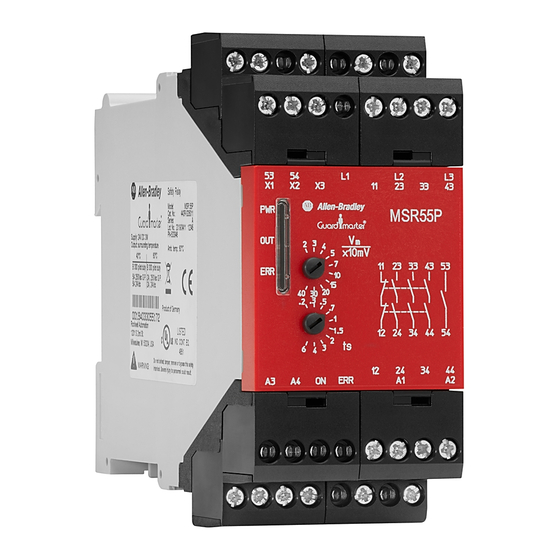
Figure 5 on page 14 shows the front face marking of each of the relays, including the terminal and status indicator identifications. The difference between the two models is the standstill monitoring voltage, V . In Rockwell Automation Publication 440R-UM014D-EN-P - December 2019... -
Page 14: Connect Power Supply
Power for the MSR55P safety relay depends on the model. The primary power Connect Power Supply supply is connected to terminals A1 and A2. An auxiliary (12…30V DC only) supply voltage can be connected to terminals A3/A4 to provide semiconductor diagnostics. Rockwell Automation Publication 440R-UM014D-EN-P - December 2019... -
Page 15: Motor Winding Inputs
L2 and L3. Figure 7 - Motor Connections L1 N L1 L2 43 53 X1 X2 43 53 X1 X2 34 44 ON ERR A4 34 44 ON ERR A4 Single-phase and DC Motor 3-phase Rockwell Automation Publication 440R-UM014D-EN-P - December 2019... -
Page 16: Safety Outputs
The currents in contact paths 23/24, 33/34 and 43/44 Then, use the graph in Figure 9 to find the highest ambient temperature that is allowed. Figure 9 - Safety Output Derating Curve Ambient Temperature (°C) Rockwell Automation Publication 440R-UM014D-EN-P - December 2019... -
Page 17: Surge Suppressors
For outputs that use 120V AC or 240V AC, we recommend metal oxide varistors. Some devices, like the Bulletin 100S-C EJ and 100S-C QJ safety contactors have built-in suppression, therefore additional suppression devices are not needed. Rockwell Automation Publication 440R-UM014D-EN-P - December 2019... -
Page 18: Auxiliary Outputs
24V DC or L1 115V AC 12...30V DC or L1 230V AC 43 53 X1 X2 34 44 ON ERR A4 DC Input DC or AC Input 24V Com OV DC or L2 (Neutral) Rockwell Automation Publication 440R-UM014D-EN-P - December 2019... -
Page 19: Monitoring Input
43 53 X1 X2 43 53 X1 X2 34 44 ON ERR A4 34 44 ON ERR A4 Guard Locking Device (Power to Unlock) Unlock Command 24V Com 24V Com No Monitoring Contactor Monitoring Rockwell Automation Publication 440R-UM014D-EN-P - December 2019... -
Page 20: Fault Reset Input
Figure 13 - Fault Reset Circuit Examples 43 53 X1 X2 43 53 X1 X2 34 44 ON ERR A4 34 44 ON ERR A4 Automatic Fault Reset Manual Fault Reset Rockwell Automation Publication 440R-UM014D-EN-P - December 2019... -
Page 21: Vm - Monitoring Voltage
Table 4 shows the settings of each of the catalog numbers. Table 4 - V - Monitoring Voltage Settings 440R-S35014, 440R-S35015, 440R-S35016 440R-S35011, 440R-S35012, 440R-S35013 Position [Volts] [x10mV] Rockwell Automation Publication 440R-UM014D-EN-P - December 2019... -
Page 22: Ts - Time Delay
During the timing cycle, the OUT indicator flashes. Table 5 shows the delay time for each setting. After the delay expires, the outputs are energized. Table 5 - Delay Time Settings Position Delay Time [seconds] Rockwell Automation Publication 440R-UM014D-EN-P - December 2019... -
Page 23: Timing Diagram Procedure
IMPORTANT The MSR55P safety relay does not detect line breakage with motor running and connected to an electronic drive. 12. The line break is reinstated. 13. Upon closure of the reset signal, the outputs are energized. Rockwell Automation Publication 440R-UM014D-EN-P - December 2019... - Page 24 10 11 12 13 A1/A2 motor speed / voltage Voltage level (V m ) L1/L2/L3 line breakage L1/L2/L3 23-24 33-34 43-44 53-54 11-12 Standstill delay time t s =2...2.5s Start up delay time Rockwell Automation Publication 440R-UM014D-EN-P - December 2019...
- Page 25 When multiple faults exist simultaneously, the ERR indicator shows the highest priority. After the highest priority fault is corrected, the ERR shows the next highest priority fault. Figure 15 on page 26 shows the codes in order of priority. Rockwell Automation Publication 440R-UM014D-EN-P - December 2019...
-
Page 26: Chapter 6 Err Flashing Codes
– The outputs of the MSR55P safety relay remain de-energized. – The ERR output turns ON. – The ERR status indicator flashes the code that is associated with the breakage. Rockwell Automation Publication 440R-UM014D-EN-P - December 2019... -
Page 27: Simultaneity Of Measuring Signals
If another setting is detected on the two corresponding potentiometers, the potentiometer error V or t displayed. To correct the fault, try to readjust the potentiometer. Make sure that you feel the detent. Rockwell Automation Publication 440R-UM014D-EN-P - December 2019... -
Page 28: Internal Device Failure
• Failure on safety relays (for example, welded output contacts). • Internal failures on measuring channels and measuring circuits. • Internal failures on control circuits for the safety relays. Cycle power to terminal A1 to clear the fault. Rockwell Automation Publication 440R-UM014D-EN-P - December 2019... -
Page 29: Guard Locking And E-Stop With Electronic Drive
2. STO of the drive when the gate is unlocked or the e-stop is pressed. This safety function is limited to Cat 3, PLd, SIL 2 due to the rating of the PF525. For guidance on safety system analysis with frequency drives, refer to https://www.dguv.de/medien/ifa/en/pub/rep/pdf/reports2013/ifar0713e/ rep0713engl.pdf" IFA Report 7/2013e, “Safe drive controls with frequency converters.” Rockwell Automation Publication 440R-UM014D-EN-P - December 2019... - Page 30 .2 .3 .5 .7 Gate control power supply 440R-D22S2 34 44 34 44 ON ERR A4 Gate control circuit Green ON Status Gate ON Status Unlocked Shielded Cable Error Status 800FM-P4MN3R 24V DC Com Rockwell Automation Publication 440R-UM014D-EN-P - December 2019...
-
Page 31: E-Stop With Contactors
2 3 4 5 MSR55P RESET x10mV 440R-S35011 .2 .3 .5 .7 440R-S12R2 34 44 ON ERR A4 Safety Devices K1 K2 ON Status 100S Contactors ON Status Error Status 24V DC Com Rockwell Automation Publication 440R-UM014D-EN-P - December 2019... -
Page 32: Wye-Delta Connections
• With3-phase connection of MSR55P safety relay, the wye contactor (K2) must be closed after the motor is switched off to detect standstill. If not the failure signal “broken wire” blocks the output contacts in the off position. Rockwell Automation Publication 440R-UM014D-EN-P - December 2019... -
Page 33: Tools Needed
• Medium-sized Screwdriver: For terminal screws, to remove terminal blocks, and to configure the switches on the front face of the relays. 0.5 mm (0.02 in.) 3 mm (0.12 in.) • Digital Multimeter: To measure signal levels and contact resistance. Rockwell Automation Publication 440R-UM014D-EN-P - December 2019... -
Page 34: Follow These Steps
ERR indicator (page contactors off? (page flashes 2x or 3x? Go to Step 4 ERR indicator Output on while Go to Step 8 (page flashes 4x? (page motor still on? Relay is functioning properly Rockwell Automation Publication 440R-UM014D-EN-P - December 2019... -
Page 35: View Pwr Indicator (Step 1)
MSR55P safety relay. Figure 20 - Measure Supply Voltage at the Terminals MSR55P 43 53 Acceptable Ranges 21.6…28.8V DC 44 54 92…126.5V AC Volts 184…253V AC Rockwell Automation Publication 440R-UM014D-EN-P - December 2019... -
Page 36: Err Indicator Flashes One Time (Step 2)
Use an ohmmeter to measure the resistance of the motor windings at L2 or L3 to L1, as shown in Figure • OK - a low resistance • Not good - the meter shows an open circuit, Rockwell Automation Publication 440R-UM014D-EN-P - December 2019... -
Page 37: Feedback Circuit Open (Step 4)
Figure 22 - Measure the Resistance in the Feedback Circuit Acceptable Range <2 ohm Ohms 43 53 X1 X2 L1 L2 L3 34 44 ON ERR A4 First, remove power to L1, L2, and L3 Rockwell Automation Publication 440R-UM014D-EN-P - December 2019... -
Page 38: Err Indicator Flashes 5 Times (Step 5)
ON. To correct this situation, try to rotate the switch to a new position and then back to the desired position. If the fault is not corrected, then replace the MSR55P safety relay. Rockwell Automation Publication 440R-UM014D-EN-P - December 2019... -
Page 39: Output Is Energized But Contactors Are Off (Step 7)
L2/L3 to L1) or the motor generates only a low voltage. Check connection of measuring inputs to motor winding according to the connection examples. Increase the delay time t setting to allow the motor more time to spin to a stop. Rockwell Automation Publication 440R-UM014D-EN-P - December 2019... - Page 40 Chapter 8 Troubleshooting Notes: Rockwell Automation Publication 440R-UM014D-EN-P - December 2019...
-
Page 41: General
11/12,23/24,33/34,43/44 against all others 11/12,23/24,33/34,43/44 against each other 53/54 against all others IEC/EN 60664-1 A3/ON/ERR/A4 against all others A1/A2 AC against all others A1/A2 DC against all others X1/X2/X3 to L1/L2/L3 No galvanic separation Rockwell Automation Publication 440R-UM014D-EN-P - December 2019... -
Page 42: Power Supply (A1/A2)
Table 15 - Status Output Specifications Attribute Value A3/A4 power supply voltage range [V DC] 12…30 PELV/SELV or Class 2 Power consumption [W] ON, ERR max current at 24V DC [mA] 53/54 contact rating [A/VAC] 3/250 Rockwell Automation Publication 440R-UM014D-EN-P - December 2019... -
Page 43: Appendix B Agency Certification
Electromagnetic compatibility (EMC) – Generic standards – Immunity requirements for equipment intended to perform functions in a safety- related system (functional safety) in industrial locations This product is intended for use in an industrial environment. Rockwell Automation Publication 440R-UM014D-EN-P - December 2019... -
Page 44: Machine Safety Directive
Specifications are applicable only if the safety function is demanded at least once within six months. All diagnostic tests are conducted at least before next demand. At mission time (TM), the proof test interval (PTI) is assumed. Components failure rates are according to SN29500. Rockwell Automation Publication 440R-UM014D-EN-P - December 2019... -
Page 45: Sil Rating
ISO 13849-1. Table 17 - Performance Level/Category Attribute Rating Category Performance Level MTTF [years] Diagnostic Coverage, DC 99.0 Days, d [days/year] Hours, h [hours/day] [s/cycle] 28.8E cycle T [years] Rockwell Automation Publication 440R-UM014D-EN-P - December 2019... - Page 46 Appendix B Regulatory Approval Notes: Rockwell Automation Publication 440R-UM014D-EN-P - December 2019...
-
Page 47: Index
ERR indicator machine safety directive 44 flashes 1 time 36 measuring signal flashes 5 times 38 simultaneity 27 flashes 6 or 7 times 38 monitoring input 19 error monitoring voltage 21 potentiometer 27 Rockwell Automation Publication 440R-UM014D-EN-P - December 2019... - Page 48 13 L1, L2, or L3 36 wiring recommendation 13 requirements 13 safety wiring example 29 output 16 wye-delta safety output connection 32 specification 42 SIL rating 45 simultaneity measuring signal 27 Rockwell Automation Publication 440R-UM014D-EN-P - December 2019...
- Page 50 How Are We Doing? form at http://literature.rockwellautomation.com/idc/groups/literature/documents/du/ra-du002_-en-e.pdf. Rockwell Automation maintains current product environmental information on its website at http://www.rockwellautomation.com/rockwellautomation/about-us/sustainability-ethics/product-environmental-compliance.page. Allen-Bradley, Guardmaster, Minotaur, PowerFlex, Rockwell Automation, and Rockwell Software are trademarks of Rockwell Automation, Inc. Trademarks not belonging to Rockwell Automation are property of their respective companies.
Need help?
Do you have a question about the Allen-Bradley GuardMaster MSR55P Back EMF Minotaur and is the answer not in the manual?
Questions and answers