Sign In
Upload
Manuals
Brands
Rockwell Automation Manuals
Relays
Guardmaster MSR57P
Rockwell Automation Guardmaster MSR57P Manuals
Manuals and User Guides for Rockwell Automation Guardmaster MSR57P. We have
4
Rockwell Automation Guardmaster MSR57P manuals available for free PDF download: User Manual, Release Note
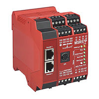
Rockwell Automation Guardmaster MSR57P User Manual (246 pages)
Speed Monitoring Safety Relay
Brand:
Rockwell Automation
| Category:
Relays
| Size: 31 MB
Table of Contents
Table of Contents
5
About this Publication
11
Conventions
11
Preface
11
Terminology
11
Who Should Use this Manual
11
Additional Resources
13
Chapter 1 Introduction
15
Safety Certification
15
Important Safety Considerations
16
Safety Category 4 Performance Definition
17
Stop Category Definitions
17
Performance Level and Safety Integrity Level (SIL) 3
18
Functional Proof Tests
18
PFD and PFH Definitions
18
PFD and PFH Data
19
Safe State
19
Safety Reaction Time
20
Considerations for Safety Ratings
20
Output Pulse Test Considerations
21
Considerations for Single-Encoder Applications
21
Contact Information if Device Failure Occurs
24
Introduction
25
Safety Functions
25
Safety Modes
26
Disabled Mode
26
Lock Monitoring
27
Safe Maximum Speed, Safe Maximum Acceleration, and Safe Direction Monitoring
27
Hardware Features
28
Configuration
29
Introduction
31
General Safety Information
32
Environment and Enclosure
33
Considerations for Reducing Noise
33
Dimensions
33
Spacing Requirements
34
Mount the MSR57P Relay
34
Power Supply Requirements
34
Removable Terminal Blocks
35
Circuit Diagram
35
Terminal Connections
36
Compatible Encoders
37
Connect an Encoder
38
Encoder Cable Specifications
44
Feedback Cable Connections for Motion Control Applications
44
Flying-Lead Feedback Cable Pin-Outs
46
Wiring Low-Profile Connector Kits
53
Feedback Connections for Powerflex 70 Drives
54
Safe off Board Terminal Block (Enhanced Control Only)
55
Encoder Interface Terminal Block (Enhanced Control Only)
55
Feedback Connections for Powerflex 700S Drives
57
Connect a Configuration Device
57
Speed Monitoring I/O Signals
59
Introduction
59
Inputs
59
Safe Stop Input (Ss_In)
62
Safe Limited Speed Input (Sls_In)
62
Door Monitor Input (Dm_In)
62
Enabling Switch Monitor Input (Esm_In)
63
Lock Monitor Input (Lm_In)
63
Reset Input (Reset_In)
64
Reset Loop Input (Rl_In)
65
Outputs
65
Safety Control Outputs
65
Diagnostic Outputs
72
General Relay and Feedback Monitoring Configuration
75
Introduction
75
Cascaded Configuration
75
Safety Mode
76
Reset Type
76
Reset Qualification
77
Overspeed Response Time
77
Speed Resolution Accuracy for Rotary Systems
78
Speed Resolution Accuracy for Linear Systems
80
Language Code
81
Max Display Speed
82
General Parameter List
82
Feedback Monitoring
83
Feedback Polarity
84
Single Encoder
84
Dual Encoders
84
Feedback Voltage Monitor Range
87
Feedback Fault
88
Feedback Parameter List
88
Introduction
91
Safe Stop Mode
91
Safe Stop Types
92
Standstill Speed and Position Tolerance
95
Deceleration Monitoring
96
Safe Stop Reset
97
Door Control
99
Lock Monitoring
101
Safe Stop Parameter List
101
Safe Stop Wiring Example
104
Safe Stop with Door Monitoring Mode
104
Lock Monitoring
105
SS Reset
105
Safe Stop with Door Monitoring Parameter List
105
Safe Stop with Door Monitoring Wiring Example
106
Safe Limited Speed (SLS) Modes
107
Introduction
107
Safe Limited Speed (SLS) Mode
107
Safe Limited Speed Reset
109
Safe Limited Speed Parameter List
110
Safe Limited Speed Wiring Example
111
Safe Limited Speed with Door Monitoring Mode
112
Safe Limited Speed Reset
113
SLS with Door Monitoring Parameter List
113
SLS with Door Monitoring Wiring Example
114
Mode
114
Safe Stop Reset (SS Reset) and Safe Limited Speed Reset (SLS Reset)
115
SLS with Enabling Switch Monitoring Parameter List
116
SLS with Enabling Switch Monitoring Wiring Example
117
Safe Limited Speed with Door Monitoring and Enabling Switch Monitoring Mode
117
Behavior During SLS Monitoring
119
Behavior While SLS Monitoring Is Inactive
119
Behavior During SLS Monitoring Delay
119
Safe Stop Reset (SS Reset) and Safe Limited Speed Reset (SLS Reset)
120
Parameter List
120
SLS with Door Monitoring and Enabling Switch Monitoring Wiring Example
121
Safe Limited Speed Status Only Mode
121
Speed Hysteresis
122
SLS Status Only Parameter List
123
SLS Status Only Wiring Examples
124
Chapter 8 Introduction
127
Cascaded Configurations
127
Slave, Safe Stop Mode
129
Slave, Safe Stop Parameter List
129
Slave, Safe Stop Wiring Examples
131
Slave, Safe Limited Speed Mode
134
Slave, Safe Limited Speed Parameters
134
Slave, Safe Limited Speed Wiring Examples
135
Slave, Safe Limited Speed Status Only Mode
137
Slave, Safe Limited Speed Status Only Parameter List
137
Slave, Safe Limited Speed Status Only Wiring Examples
137
Multi-Axis Connections
139
Cascaded System Examples
141
Introduction
147
Safe Maximum Speed (SMS) Monitoring
147
Safe Maximum Acceleration (SMA) Monitoring
150
Safe Direction Monitoring (SDM)
152
Max Speed, Max Accel, and Direction Monitoring
153
Parameter List
153
Introduction
155
Safety Configuration
155
Configuration Signature ID
155
Safety-Lock
155
Set a Password
156
Reset the Password
157
Reset the Relay
157
Basics of Application Development and Testing
158
Commissioning the System
158
Specify the Safety Configuration
159
Configure the Speed Monitoring Relay
160
Project Verification Test
161
Confirm the Project
161
Safety Validation
161
Relay
161
Editing the Configuration
162
Configuration Examples
163
Introduction
163
Example Application 1
163
Example 1: Initial Security Group Settings
164
Example 1: General Group Settings
165
Example 1: Feedback Group Settings
166
Example 1: Stop Group Settings
168
Example 1: Limited Speed Group Settings
170
Example 1: Door Control Group Settings
171
Example 1: Max Speed Group
172
Example 1: Final Security Group Settings
173
Example Application 2
174
Example 2: Initial Security Group Settings
175
Example 2: General Group Settings
176
Example 2: Feedback Group Settings
177
Example 2: Stop Group Settings
179
Example 2: Limited Speed Group Settings
181
Example 2: Door Control Group Settings
183
Example 2: Max Speed Group
184
Example 2: Final Security Group Settings
185
Troubleshoot the MSR57P Relay
187
Introduction
187
Status Indicators
187
Nonrecoverable Faults
188
Fault Recovery
189
Input and Output Faults
189
Fault Codes and Descriptions
189
Fault Reactions
192
Safe State Faults
192
Stop Category Faults and Fault While Stopping Faults
193
Status Attributes
194
Guard Status Attributes
194
I/O Diagnostic Status Attributes
197
Configuration Fault Codes
198
Introduction
199
General Specifications
199
Environmental Specifications
200
Certifications
201
Encoder Specifications
201
Parameter Groups
203
Parameters and Settings in a Linear List
204
Introduction
215
Connect a HIM Module
215
Setting Parameters with a HIM Module
216
Accessing the Fault History Queue
217
Appendix D Introduction
219
Connect a Personal Computer
219
Using Driveexplorer Software
220
Configure Serial Communication
220
Edit Parameters in Driveexplorer Software
221
Access the Fault History Queue
222
Using Driveexecutive Software
223
Configure Serial Communication
223
Edit Parameters
226
Introduction
229
Powerflex 70 Drive with Safe-Off Application Example
230
Powerflex 700 Drive Without Safe-Off
233
Kinetix 6000 or Kinetix 7000 Drives with Safe-Off Example
235
Kinetix 2000 Drive Without Safe-Off Example
237
Advertisement
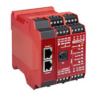
Rockwell Automation Guardmaster MSR57P User Manual (182 pages)
Speed Monitoring Safety Relay
Brand:
Rockwell Automation
| Category:
Relays
| Size: 11 MB
Table of Contents
Table of Contents
3
About this Publication
9
Summary of Changes
9
Who Should Use this Manual
9
Conventions
9
Terminology
10
Additional Resources
11
Safety Concept
13
Introduction
13
Safety Certification
13
Important Safety Considerations
13
Safety Category 4 Performance Definition
14
Stop Category Definitions
14
Performance Level and Safety Integrity Level (SIL) 3
14
Functional Proof Tests
15
PFD and PFH Definitions
15
PFD and PFH Data
15
Safe State
15
Safety Reaction Time
16
Considerations for Safety Ratings
16
Output Pulse Test Considerations
16
Considerations for Single-Encoder Applications
17
Contact Information if Device Failure Occurs
18
Introduction
19
Safety Functions
19
Safety Modes
19
Disabled Mode
20
Lock Monitoring
20
Direction Monitoring
20
Hardware Features
21
Configuration
21
Installation and Wiring
23
Introduction
23
General Safety Information
23
Environment and Enclosure
24
Considerations for Reducing Noise
24
Dimensions
24
Space Requirements
24
Mount the MSR57P Safety Relay
25
Power Supply Requirements
25
Removable Terminal Blocks
25
Circuit Diagram
26
Terminal Connections
26
Compatible Encoders
27
Connect an Encoder
27
Encoder Cable Specifications
32
Feedback Cable Connections for Motion Control Applications
33
Flying Lead Feedback Cable Pinouts
35
Wiring Low-Profile Connector Kits
38
Feedback Connections for Powerflex 70 Drives
39
Safe Torque off Terminal Block (Enhanced Control Only)
40
Encoder Interface Terminal Block (Enhanced Control Only)
40
Feedback Connections for Powerflex 700S Drives
41
Connect a Configuration Device
42
Introduction
43
Inputs
43
Safe Stop Input (Ss_In)
45
Safely-Limited Speed Input (Sls_In)
45
Door Monitor Input (Dm_In)
45
Enabling Switch Monitor Input (Esm_In)
45
Lock Monitor Input (Lm_In)
46
Reset Input (Reset_In)
46
Reset Loop Input (Rl_In)
47
Outputs
47
Safety Control Outputs
48
Diagnostic Outputs
52
Introduction
55
Cascaded Configuration
55
Safety Mode
55
Reset Type
55
Reset Qualification
56
Overspeed Response Time
56
Speed Resolution Accuracy for Rotary Systems
56
Speed Resolution Accuracy for Linear Systems
58
Language Code
59
Max Display Speed
60
General Parameter List
60
Feedback Monitoring
61
Feedback Polarity
61
Single Encoder
61
Dual Encoders
62
Feedback Voltage Monitor Range
64
Feedback Fault
64
Feedback Parameter List
65
Safe Stop and Safe Stop with Door Monitoring Modes
67
Introduction
67
Safe Stop Mode
67
Safe Stop Types
67
Standstill Speed and Position Tolerance
70
Deceleration Monitoring
71
Safe Stop Reset
71
Door Control
72
Lock Monitoring
74
Safe Stop Parameter List
74
Safe Stop Wiring Example
76
Safe Stop with Door Monitoring Mode
76
Lock Monitoring
77
SS Reset
77
Safe Stop with Door Monitoring Parameter List
77
Safe Stop with Door Monitoring Wiring Example
78
Safely-Limited Speed (SLS) Modes
79
Introduction
79
Safely-Limited Speed (SLS) Mode
79
Safely-Limited Speed Reset
80
Safely-Limited Speed Parameter List
81
Safely-Limited Speed Wiring Example
82
Safely-Limited Speed with Door Monitoring Mode
82
Safely-Limited Speed Reset
83
SLS with Door Monitoring Parameter List
83
SLS with Door Monitoring Wiring Example
84
Safely-Limited Speed with Enabling Switch Monitoring Mode
84
Safe Stop Reset (SS Reset) and Safely-Limited Speed Reset
85
(SLS Reset)
85
SLS with Enabling Switch Monitoring Parameter List
85
SLS with Enabling Switch Monitoring Wiring Example
86
Monitoring Mode
86
Behavior During SLS Monitoring
87
Behavior While SLS Monitoring Is Inactive
87
Behavior During SLS Monitoring Delay
88
Safe Stop Reset (SS Reset) and Safely-Limited Speed Reset
88
(SLS Reset)
88
SLS with Door Monitoring and Enabling Switch Monitoring
88
Parameter List
88
SLS with Door Monitoring and Enabling Switch Monitoring Wiring
89
Example
89
Safely-Limited Speed Status Only Mode
90
Speed Hysteresis
90
SLS Status Only Parameter List
91
SLS Status Only Wiring Examples
92
Cascaded Configurations
95
Slave, Safe Stop Mode
96
Slave, Safe Stop Parameter List
96
Slave, Safe Stop Wiring Examples
97
Slave, Safely-Limited Speed Mode
100
Slave, Safely-Limited Speed Parameters List
100
Slave, Safely-Limited Speed Wiring Examples
100
Slave, Safely-Limited Speed Status Only Mode
102
Slave, Safely-Limited Speed Status Only Parameter List
103
Slave, Safely-Limited Speed Status Only Wiring Examples
103
Multi-Axis Connections
105
Cascaded System Examples
107
Safe Maximum Speed (SMS) Monitoring
113
Safe Maximum Acceleration (SMA) Monitoring
115
Safe Direction Monitoring (SDM)
117
Max Speed, Max Accel, and Direction Monitoring Parameter List
119
Safety Configuration
121
Configuration Signature ID
121
Safety-Lock
121
Set a Password
122
Reset the Password
122
Reset the Safety Relay
122
Basics of Application Development and Testing
123
Commissioning the System
123
Specify the Safety Configuration
123
Configure the Speed Monitoring Safety Relay
124
Project Verification Test
125
Confirm the Project
125
Safety Validation
125
Verify the Signature and Lock at the Speed Monitoring
125
Safety Relay
125
Editing the Configuration
125
Introduction
127
Example Application 1
127
Initial Security Group Settings
127
General Group Settings
128
Feedback Group Settings
129
Stop Group Settings
130
Limited Speed Group Settings
131
Door Control Group Settings
132
Max Speed Group
133
Final Security Group Settings
133
Example Application 2
134
Initial Security Group Settings
135
General Group Settings
136
Feedback Group Settings
137
Stop Group Settings
138
Limited Speed Group Settings
139
Door Control Group Settings
140
Max Speed Group
141
Final Security Group Settings
141
Status Indicators
143
Nonrecoverable Faults
144
Fault Recovery
144
Input and Output Faults
144
Fault Codes and Descriptions
144
Fault Reactions
146
Safe State Faults
146
Stop Category Faults and Fault While Stopping Faults
146
Status Attributes
147
Guard Status Attributes
148
I/O Diagnostic Status Attributes
149
Configuration Fault Codes
150
General Specifications
151
Environmental Specifications
152
Certifications
152
Encoder Specifications
152
Parameter Groups
153
Parameters and Settings in a Linear List
154
Connect a HIM
161
Setting Parameters with a HIM
161
Accessing the Fault History Queue
162
Connect a Personal Computer
163
Using Driveexplorer Software
164
Configure Serial Communication
164
Edit Parameters in Driveexplorer Software
164
Access the Fault History Queue
165
Using Driveexecutive Software
165
Configure Serial Communication
166
Edit Parameters
167
Introduction
169
Powerflex 70 Drive with Safe Torque off Application Example
169
Powerflex 700 Drive Without Safe Torque off
172
Safe Torque off Example
174
Kinetix 2000 Drive Without Safe Torque off Example
176
Index
177
Rockwell Automation Guardmaster MSR57P User Manual (20 pages)
Speed Monitoring Safety Relay
Brand:
Rockwell Automation
| Category:
Relays
| Size: 0 MB
Table of Contents
Table of Contents
3
About this Publication
9
Conventions
9
Preface
9
Terminology
9
Who Should Use this Manual
9
Additional Resources
11
Chapter 1 Introduction
13
Safety Certification
13
Important Safety Considerations
14
Safety Category 4 Performance Definition
15
Stop Category Definitions
15
Performance Level and Safety Integrity Level (SIL) 3
16
Functional Proof Tests
16
PFD and PFH Definitions
16
PFD and PFH Data
17
Safe State
17
Safety Reaction Time
18
Considerations for Safety Ratings
18
Output Pulse Test Considerations
19
Considerations for Single-Encoder Applications
19
Advertisement
Rockwell Automation Guardmaster MSR57P Release Note (8 pages)
Speed Monitoring Safety Relay
Brand:
Rockwell Automation
| Category:
Relays
| Size: 0 MB
Table of Contents
About this Publication
1
Before You Begin
1
Update Firmware
3
Corrected Anomalies
3
Confirm the Update
6
Download Your Saved Configuration File
6
Additional Resources
7
Rockwell Automation Support
8
Installation Assistance
8
New Product Satisfaction Return
8
Advertisement
Related Products
Rockwell Automation Allen-Bradley Guardmaster MSR55P
Rockwell Automation Allen-Bradley Guard master MSR22LM
Rockwell Automation Allen-Bradley Guardmaster MSR210
Rockwell Automation Allen-Bradley Guardmaster MSR200
Rockwell Automation Allen-Bradley Guardmaster MSR220
Rockwell Automation Allen-Bradley Guardmaster MSR230
Rockwell Automation Allen-Bradley Guardmaster MSR238
Rockwell Automation Allen-Bradley Guardmaster MSR245
Rockwell Automation Guardmaster Allen-Bradley 440R-S35001
Rockwell Automation Guardmaster Allen-Bradley 440R-S35003
Rockwell Automation Categories
Controller
Control Unit
Power Supply
DC Drives
Industrial Equipment
More Rockwell Automation Manuals
Login
Sign In
OR
Sign in with Facebook
Sign in with Google
Upload manual
Upload from disk
Upload from URL