
Related Manuals for Rockwell Automation Allen-Bradley Guardmaster MSR210


Summary of Contents for Rockwell Automation Allen-Bradley Guardmaster MSR210
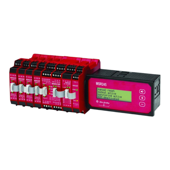
- Page 1 Safety Relay Troubleshooting Guide Troubleshooting Safety Relay Based Systems MSR210 MSR200 Toubleshooting Guide Rev A.doc Page 1 of 14...
-
Page 2: Table Of Contents
Table of Contents Introduction............................3 Product Description ..........................3 Power Supply ............................4 FAQ: How does the MSR210 react to momentary power interruptions?..............4 Input Circuits – General........................5 Input Circuit – 2NC ..........................6 FAQ: How much contact bounce can the MSR210 withstand on its inputs? ...............7 FAQ: How does the MSR210 respond to input signals that are shorter than the input recovery time?......7 FAQ: Can a 700-P or 700S-P relay be used as an input device to the MSR210?............8 Reset Circuit............................ -
Page 3: Introduction
Introduction The troubleshooting process for the MSR200 safety relay follows a straight forward process. The process starts with the power supply and follows the normal sequence of events that take place in the relay. The troubleshooting process is as follows: 1. -
Page 4: Power Supply
Power Supply The power supply is protected by electronic current limiting. If a short circuit or overload occurs, the resistance goes up to prevent damage to the MSR200. When the fault is cleared, the resistance returns to normal, and the MSR200 begins to operate properly. -
Page 5: Input Circuits - General
Input Circuits – General The MSR210 uses pulse checking to test for shorts to power, ground and neighboring circuits. These pulses allow the MSR210 to detect a fault before a demand is placed on the safety system. When a fault is found, the safety outputs of the MSR210 de-energize. -
Page 6: Input Circuit - 2Nc
Input Circuit – 2NC The typical 2 normally closed (NC) series circuit is wired as shown below. This arrangement employs redundancy (two circuits) and checking (test pulses) to check for open and short circuits. The internal relay to CH1 is pulled up by the external interlocks or e-stops to 24V at S11. A jumper is connected from S11 to S52 to supply power to CH2. -
Page 7: A) Faq: How Much Contact Bounce Can The Msr210 Withstand On Its Inputs
Step I1 Use a DC voltmeter to measure the voltage of the input signals. Since the input signals are pulsed (see figure below), the actual measured values may vary due to the meter, supply voltage, and unit-to-unit variation. Measure Gate open Gate closed Current (Scope) Current (meter) Source... -
Page 8: C) Faq: Can A 700-P Or 700S-P Relay Be Used As An Input Device To The Msr210
Recycle inputs for 20ms and output turns on Recycle again and outputs are off with Stop LED blinking continuously. Oscillates between an off and on state and then eventually the Stop led is blinking continuously. At 14-15ms, Sometimes the input cycles and causes the output to turn off. Sometimes, the MSR210 does not respond. -
Page 9: Reset Circuit
Reset Circuit Operation The MSR200 provides two terminals (Y41/Y40) to configure the reset type and two terminals (Y1/S34) to connect a reset button if needed. There are two types of reset functions: automatic and monitored. Power to the MSR210 must be cycled after any change to the Y40/Y41/Y42 if the change was made with power applied. -
Page 10: A) Faq: How Long Must The Reset Signal Be
Monitored Reset Button Y1/A2 S34/A2 Status & Action Released 22V DC 0VDC MSR200 working OK Pressed 22V DC 22V DC MSR210 working OK Step R2 Measure the Y40 signal on an oscilloscope. Timebase is 2ms/div. Voltage is 10V/div. The pulse width changes when the input is opened or closed. -
Page 11: Monitoring Circuit
Monitoring Circuit Operation The MSR210 provides two terminals (Y42/Y40) to enable external device monitoring (EDM) and two terminals (Y1/Y2) to connect a monitoring circuit. The MSR210 has dynamic checking of the EDM circuit. An oscilloscope is needed to see the waveform shown below. Disable EDM: To disable EDM, connect a jumper between Y42/Y40 and Y1/Y2. -
Page 12: A) Faq: When I Press The Reset Button, The Output Turns On Momentarily, Then The Stop Led Starts Blinking
a) FAQ: When I press the reset button, the output turns on momentarily, then the Stop LED starts blinking. This occurs when MSR210 is configured for EDM (no jumper from Y40/Y412) and a jumper exists on Y1/Y2. If EDM is needed, then the Y1/Y2 circuit must open shortly after the safety outputs are energized. b) FAQ: When I enable EDM and short out the Y1/Y2, the MSR210 still energizes its output. -
Page 13: Output Circuits - Base Module
Output Circuits – Base Module The output circuits are redundant voltage-free, electromechanical contacts. Initial contact resistance should be less than 1 ohm. Over the life of the contacts, resistance may go up, but should remain less than a couple ohms. Follow the steps below using the figure below as a guide. -
Page 14: Output Circuits - Msr230 And Msr238
Output Circuits – MSR230 and MSR238 Modules The MSR210 can accept up to two output modules, which are mounted to the right of the MSR210 and connected to the MSR210 by ribbon cables. The MSR230 has only immediate operating outputs, which mimic the safety outputs of the MSR210.
Need help?
Do you have a question about the Allen-Bradley Guardmaster MSR210 and is the answer not in the manual?
Questions and answers