Table of Contents
Advertisement
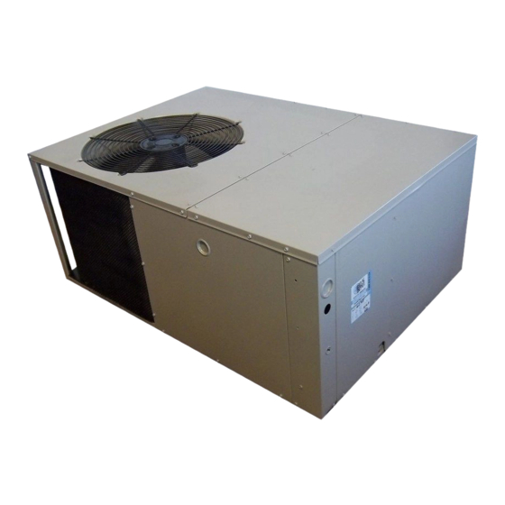
P5RD SERIES
USER's MANUAL & INSTALLATION INSTRUCTIONS
R-410A Single Package Air Conditioner
Please read this information thoroughly and become familiar with the capabilities and use of
your appliance before attempting to operate or maintain this unit. Keep this literature where
you have easy access to it in the future. If a problem occurs, check the instructions and follow
recommendations given. If these suggestions don't eliminate your problem, call your servicing
contractor.
These instructions are primarily intended to assist qualifi ed individuals experienced in the
proper installation of this appliance. Some local codes require licensed installation/service
personnel for this type of equipment. Please read all instructions carefully before starting the
installation.
IMPORTANT
DO NOT DESTROY. PLEASE READ CAREFULLY AND
KEEP IN A SAFE PLACE FOR FUTURE REFERENCE.
13 SEER
Advertisement
Table of Contents

Subscribe to Our Youtube Channel
Related Manuals for Nordyne P5RD Series


Summary of Contents for Nordyne P5RD Series
- Page 1 P5RD SERIES 13 SEER USER’s MANUAL & INSTALLATION INSTRUCTIONS R-410A Single Package Air Conditioner IMPORTANT Please read this information thoroughly and become familiar with the capabilities and use of your appliance before attempting to operate or maintain this unit. Keep this literature where you have easy access to it in the future.
-
Page 2: Table Of Contents
USER INFORMATION Important Safety Information ........3 WARRANTY INFORMATION Operating Instructions ..........3 A warranty certifi cate with full details is included with the Cooling Operation .............3 Air Conditioner. Carefully review these responsibilities with Heating Operation .............3 your dealer or service company. The manufacturer will not Turning the Air Conditioner Off ........3 be responsible for any costs found necessary to correct Operating the Indoor Blower Continuously ....3... -
Page 3: Important Safety Information
USER INFORMATION IMPORTANT SAFETY INFORMATION Turning the Air Conditioner OFF Change the thermostat’s system mode to OFF and the fan Safety markings are used to designate a degree or level mode to AUTO (See Figure 1). NOTE: The system will not of seriousness and should not be ignored. -
Page 4: Important Safety Information
INSTALLER INFORMATION IMPORTANT SAFETY INFORMATION CAUTION: Please read all instructions before servicing this equipment. Pay attention to all safety warnings and any other special This unit uses refrigerant R-410A. DO NOT use notes highlighted in the manual. Safety markings are any other refrigerant in this unit. -
Page 5: Air Conditioner Installation
AIR CONDITIONER INSTALLATION to re-circulate into the condenser air inlet, through the coil. General Information • Consideration should be given to availability of electric The P5RD packaged air conditioner is designed only power, service access, noise, and shade. for outdoor ground level installations and can be readily connected to the high static duct system of a home. -
Page 6: Condensate Drainage
Condensate Drainage DUCTING SYSTEM A 3/4” condensate fi tting extends out of the side of the Air ducts should be installed in accordance with the unit (Figure 3). The drain trap, shipped in the electrical standards of the National Fire Protection Association compartment, must be installed to prevent water from “Standard for Installation of Air Conditioning and Ventilation collecting inside the unit. -
Page 7: Return Duct
4. Tap collar (if necessary) to ensure engagement with unit opening and install second screw. 5. Tighten fi rst screw and rotate collar clockwise so joint is near three o’clock position. Return Duct 1. Align the slots with the holes in the collar and install two screws. -
Page 8: Electrical Connections
When locating the supply damper(s), carefully check ELECTRICAL CONNECTIONS fl oor joists and frame members that could interfere with the installation of the damper or fl exible duct. Ideally, the WARNING: damper (Figure 7) should be located in the bottom of the To avoid risk of electrical shock, personal main duct, forward of center of the home, at least three feet from the nearest register. -
Page 9: Overcurrent Protection
(Figures 11 & 12, pages 14 & 15)) for identifi cation and Grounding location of unit fi eld wiring interfaces. Make all electrical WARNING: connections in accordance with all applicable codes and ordinances. The unit cabinet must have an uninterrupted •... -
Page 10: Blower Speed
thermostat prevents simultaneous operation of the heating High Effi ciency Motor (3.5, 4, and 5 Ton) and cooling units and is equipped with an ON-AUTO fan 1. Disconnect all electrical power to the unit and remove mode that allows the home owner to operate the indoor the service panel. -
Page 11: Startup & Adjustments
START UP & ADJUSTMENTS Emergency Heat (Available only when Electric heat is supplied) Set the Pre-Start Checklist thermostat’s system mode to EM HT and the fan mode The following check list should be observed prior to to either AUTO (intermittent air) or to ON (continuous air). starting the unit. -
Page 12: Air Conditioner Maintenance
• Inspect the electrical connections for tightness at the beginning of each heating and cooling season. Service REPLACEMENT PARTS as necessary. Replacement parts are available through all Nordyne distributors. Please have the complete model and serial number of the unit CAUTION: when ordering replacement parts. -
Page 13: Figures & Tables
FIGURES AND TABLES Top View 9.15 1" 3.15 9.04 17.50 Electric Heater Power Supply 12" diameter 14" diameter Power Supply Supply Duct Return Duct Low Voltage Supply Opening Opening Back (Duct) View Control Blower Access Panel Access 17.86 Side View Panel 15.36 10.10... -
Page 14: Electrical Information
ELECTRICAL INFORMATION Figure 11. Wiring Diagram - P5RD with ECM Motor... - Page 15 Figure 12. Wiring Diagram - P5RD with PSC Motor...
-
Page 16: Refrigerant Charging Charts
REFRIGERANT CHARGING CHARTS Refrigerant Charging Chart Legend: Shaded boxes indicate fl ooded conditions. Rated design values. The suction pressure will vary from design value if outdoor air fl ow, entering dry bulb, or entering wet bulb temperatures vary. 1. All pressures are listed psig and all temperatures in °F 2. - Page 17 REFRIGERANT CHARGING CHARTS - CONTINUED Refrigerant Charging Chart Legend: Shaded boxes indicate fl ooded conditions. Rated design values. The suction pressure will vary from design value if outdoor air fl ow, entering dry bulb, or entering wet bulb temperatures vary. 1.
- Page 18 REFRIGERANT CHARGING CHARTS - CONTINUED Refrigerant Charging Chart Legend: Shaded boxes indicate fl ooded conditions. Rated design values. The suction pressure will vary from design value if outdoor air fl ow, entering dry bulb, or entering wet bulb temperatures vary. 1.
-
Page 20: Installation / Performance Checklist
INSTALLATION / PERFORMANCE CHECK LIST REFRIGERATION SYSTEM: INSTALLATION ADDRESS: Was unit given 24 hr warm up period for crankcase heaters? CITY ________________________ STATE ________________ Stage-1 Liquid Pressure (high side) ________________________ UNIT MODEL # ________________________________________ Stage-1 Suction Pressure (low side) ________________________ UNIT SERIAL # ________________________________________ Has the owner’s information been Unit Installed Minimum clearances per...
Need help?
Do you have a question about the P5RD Series and is the answer not in the manual?
Questions and answers