Nordyne iHybrid DF6SF Series Installation Instructions Manual
Dual fuel heating & cooling packaged system
Hide thumbs
Also See for iHybrid DF6SF Series:
- User manual (8 pages) ,
- Installation instructions manual (40 pages)
Table of Contents
Advertisement
Quick Links
DF6SF / PDF2SF - REV. B SERIES
InStAllAtIon InStRUCtIonS
Dual Fuel Heating & Cooling Packaged System
FIRE oR EXPloSIon HAZARD
• Failure to follow safety warnings
exactly could result in serious injury
or property damage.
• Installation and service must be
performed by a qualified installer,
service agency or the gas supplier.
• Do not store or use gasoline or other
flammable vapors and liquids in the
vicinity of this or any other appliance.
WHAt to Do IF YoU SMEll GAS
• Do not try to light any appliance.
• Do not touch any electrical switch; do
not use any phone in your building.
• Leave the building immediately.
• Immediately call your gas supplier
from a neighbors phone. Follow the
gas suppliers instructions.
• If you cannot reach your gas supplier,
call the fire department.
Do not DEStRoY. PlEASE READ CAREFUllY & KEEP In A SAFE PlACE FoR FUtURE REFEREnCE.
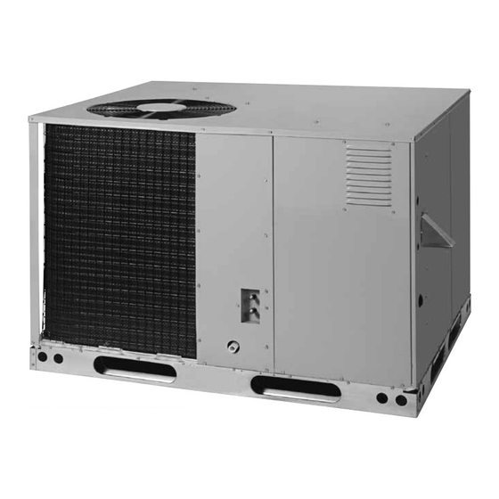
Premium Model Shown
WARnInG / AVERtISSEMEnt
15 SEER / 8.0 HSPF / 81% AFUE
RISQUE D'InCEnDIE oU D' EXPloSIon
• Le non-respect des avertissements de sécurité
pourrait entraîner des blessures graves, la mort ou
des dommages matériels.
• L'installation et l'entretien doivent être effectués par
un installateur qualifié, un organisme de service ou le
fournisseur de gazstaller, service agency or the gas
supplier.
• Ne pas entreposer ni utiliser de l'essence ni d'autres
vapeurs ou liquides inflammables dans le voisinage
de cet appareil, ni de tout autre appareil.
QUE FAIRE S'Il Y A UnE oDEUR DE GAZ
• Ne pas tenter d'allumer aucun appareil.
• Ne toucher à aucun interrupteur électrique; n'utiliser
aucun téléphone dans le bâtiment.
• Évacuer l'immeuble immédiatement.
• Appeler immédiatement le fournisseur de gaz en
employant le téléphone d'un voisin. Respecter à la
lettre les instructions du fournisseur de gaz.
• Si personne ne répond, appeler le service des
incendies.
Advertisement
Table of Contents
Troubleshooting

Subscribe to Our Youtube Channel
Related Manuals for Nordyne iHybrid DF6SF Series


Summary of Contents for Nordyne iHybrid DF6SF Series
- Page 1 DF6SF / PDF2SF - REV. B SERIES 15 SEER / 8.0 HSPF / 81% AFUE InStAllAtIon InStRUCtIonS Dual Fuel Heating & Cooling Packaged System Premium Model Shown WARnInG / AVERtISSEMEnt RISQUE D’InCEnDIE oU D’ EXPloSIon FIRE oR EXPloSIon HAZARD • Le non-respect des avertissements de sécurité •...
-
Page 2: Table Of Contents
tABlE oF ContEntS Short Cycle Protection .......... 18 IMPoRtAnt SAFEtY InFoRMAtIon ......3 System Cooling Operation (2-Stage) ....18 REQUIREMEntS & CoDES ........4 System Heating (Heat Pump Mode) ..... 18 GEnERAl InFoRMAtIon ........... 5 System Heating (Emergency Heat Mode) .... 19 Before You Install this Unit ......... -
Page 3: Important Safety Information
IMPoRtAnt SAFEtY InFoRMAtIon WARnInG: Please read all instructions before servicing this equipment. Pay attention to all safety warnings and any other special PRoPoSItIon 65 WARnInG: this product notes highlighted in the manual. Safety markings are used contains fiberglass wool, a product known frequently throughout this manual to designate a degree or to the state of California to cause cancer. -
Page 4: Requirements & Codes
• Follow all precautions in the literature, on tags, and on • Additional codes listed below are for reference purposes labels provided with the equipment. Read and thoroughly only and do not necessarily have jurisdiction over understand the instructions provided with the equipment local or state codes. -
Page 5: General Information
GEnERAl InFoRMAtIon • A clearance of at least 36 inches from the blower access panel and from the louvered control access panel is The Dual Fuel iHybrid™ heat pump is designed only for recommended for servicing and maintenance. outdoor rooftop or ground level installations and can be Where accessibility clearances are greater than readily connected to the duct system of a home. -
Page 6: Combustion Air & Venting Requirements
CoMBUStIon AIR & VEntInG REQUIREMEntS WARnInG: AVERtISSEMEnt: RISQUE D’EMPoISonnEMEnt AU CARBon MonoXIDE PoISonInG HAZARD MonoXYDE DE CARBonED Failure to follow the steps outlined below for each appliance connected to the venting system Le non-respect des consignes suivantes portant being placed into operation could result in carbon sur chacun des appareils raccordés au système monoxide poisoning or death.The following steps d’évacuation mis en service pourrait entraîner... -
Page 7: General Information
General Information If this control must be replaced, use only factory authorized replacement parts. See the Replacement Parts List on WARnInG: page 25. Vent termination Installation methods other than those described This unit has been equipped with an integral venting system in the following sections must comply with the and designed to operate only with this venting system. -
Page 8: Circulating Air Supply
• Duct work should be attached directly to the unit flanges • The unit installation shall avoid areas where condensate for horizontal applications. drainage may cause problems by dropping on planters • If roof curb is installed, the ducts must be attached to or patios, etc. -
Page 9: Unconditioned Spaces
Unconditioned Spaces • If using bottom discharge with return air ducts a roof curb must be installed prior to unit installation. See Rigging All duct work passing through unconditioned space must and Hoisting section for setting of the unit. be properly insulated to minimize duct losses and prevent •... -
Page 10: Horizontal To Downflow Conversion
Horizontal to Downflow Conversion ElECtRICAl WIRInG The unit is shipped ready for horizontal duct connections. If down flow ducts are required, the unit must be converted WARnInG: following the steps below for both the supply and return ducts. ELECTRICAL SHOCK, FIRE OR 1. -
Page 11: Line Voltage
VoltAGE RAnGE CoMPRESSoR SInGlE CIRCUIt MAXIMUM noMInAl InDooR MoDEl HEAtInG ElECtRICAl MotoR BloWER nUMBER InPUt SUPPlY X24K080CB 80,000 208-230/60/1 11.7 58.3 0.91 20.3 30.0 X36K100CB 100,000 208-230/60/1 15.3 83.0 29.0 40.0 X48K120CB 120,000 208-230/60/1 21.2 104.0 38.6 50.0 X60K120CB 120,000 208-230/60/1 28.8 152.9... -
Page 12: Heating Configuration
CoPPER WIRE SIZE — AWG RECoMMEnDED MAXIMUM (1% VoltAGE DRoP) WIRE GAUGE WIRE lEnGtH (Ft) FRoM UnIt to tHERMoStAt SUPPlY WIRE lEnGtH-FEEt SUPPlY CIRCUIt AMPACItY Table 4. thermostat Wire Gauge Before operation, the variable speed blower must be configured to match the unit with the system, climatic conditions, and other system options. -
Page 13: Selecting Gas Heating Airflow
Delay Profile removed, the defrost mode will terminate in 13.7 minutes, if the coil temperature is above the terminate set-point, The delay profile controls the start-up and shut-down or when the Y input is removed, whichever occurs first. characteristics of the packaged heat pump unit. By varying the start-up and shut-down characteristics of the packaged notE: If a demand curve is selected which has a 30 second heat pump unit, the system can be optimized for energy... -
Page 14: Optional Comfort Alert Tm Diagnostics Module
Optional Comfort Alert Diagnostics Module The Comfort Alert Diagnostics Module is a breakthrough innovation for troubleshooting heat pump and air conditioning system failures. The module installs easily in the electrical box of the outdoor unit near the compressor contactor. By monitoring and analyzing data from the Copeland scroll compressor and the thermostat demand, the module can accurately detect the cause of electrical and system related... -
Page 15: Interpreting The Diagnostic Led's
keep the solenoid pulled in. As the 24VAC supply voltage 4. Set the thermostat’s system mode to COOL. varies, Comfort Alert intelligently changes the solenoid notE: When the compressor starts to run, the Alert LED (yellow) will begin flashing a Code 8 indicating a DC voltage supply to minimize power consumption. -
Page 16: Gas Supply & Piping
GAS SUPPlY & PIPInG • Gas piping must never run in or through air ducts, chimneys, gas vents, or elevator shafts. WARnInG: • Compounds used to seal joints on gas piping must be resistant to the actions of LP propane gas. •... -
Page 17: High Altitude Conversion
If installing this unit above 2,000 feet, the input rate must Shut-Off Valve be reduced 4% per 1,000 feet of altitude (Example: 12% with 1 /8 NPT Automatic Gas Valve plugged tap at 3,000 feet, 16% at 4,000 feet, etc). notE: Deration is (with manual shut-off) necessary to compensate for low atmospheric pressure at high altitudes. -
Page 18: Startup & Adjustments
StARt UP & ADJUStMEntS Short Cycle Protection 1. With the system operating in cooling mode, note the Pre-Start Check list temperature setting of the thermostat and gradually raise √ Verify the unit is level and allows proper condensate the set-point temperature until the unit de-energizes. drainage. -
Page 19: System Heating (Emergency Heat Mode)
Verifying & Adjusting Firing Rate Gas Heating (Emergency Heat Mode) notE: When thermostat is set to the emergency heat CAUtIon: position, heat pump operation will be locked out. 1. Set the thermostat to the lowest setting. Do not re-drill the burner orifices. If the orifice 2. -
Page 20: Manifold Pressure Adjustment
end of the flame will be out of sight around the bend. Manifold Pressure (in W.C.) for 3. After validating flame characteristics, set the thermostat natural Gas Installations below room temperature and verify the burner flame Heating Value Btu/cu. ft. extinguishes completely. -
Page 21: Operating Sequence
Charging an R-410A Unit in Heating Mode de-energize the inducer for 60 minutes and continue to flash 2 during the 60 minute inducer off period. After the 1. Evacuate the refrigerant system. inducer has been off for 60 minutes, the control energizes 2. -
Page 22: 2-Stage Cooling Mode
EQUIPMEnt MAIntEnAnCE from a 2-stage thermostat. After a second stage heat demand is present (W2 energized), the gas valve will WARnInG: open to High heat mode increasing the flow of gas to the burners while the inducer and blower motor ramp to high speed. -
Page 23: Cleaning Of Heat Exchanger
5. Disconnect the wires from the gas valve, ignitor, flame CAUtIon: sensor, combustion air motor, flame roll-out control, over-temperature limit switch, and pressure switch. The unit should never be operated without a 6. Remove the silicone rubber tube from the collector pan filter in the return air system.Replace disposable to the pressure switch. -
Page 24: Cleaning Of Burners
tRoUBlESHootInG CAUtIon: If the unit does not operate in the cooling mode, check the following: To prevent damage to the unit or internal • The thermostat is operating properly components, it is recommended that two • Electrical power to the unit is turned on wrenches be used when loosening or tightening •... -
Page 25: Component Functions
REPlACEMEnt PARtS Flame Roll-Out Control - The flame roll-out control acts to Replacement parts are available through all Nordyne verify that the burner flame is being drawn into the heat distributors. Please have the complete model and serial exchanger tubes. -
Page 26: Figures & Tables
FIGURES & tABlES 3/4" NPT Female 24 9/10 Drain Connector DOWNFLOW SUPPLY DUCT OPENING 47 1/2 13 1/2 13 1/2 13 3/10 DOWNFLOW 23 1/2 RETURN DUCT Electric OPENING Supply Entry top View Low Voltage Entry Gas Supply 29.75 Entry 23.75 15.75 47.5... -
Page 27: Airflow Information
Airflow Information CoolInG MoDEl HEAtInG InPUt HEAtInG oUtPUt HEAtInG RISE BloWER MotoR oUtPUt nUMBER (BtUH) (BtUH) RAnGE RAnGE (°F) SIZE (HP) (BtUH) 80,000 64,800 1100 - 1350 X24K080CB 35-65 24,000 10 X 10 52,000 42,120 750 - 1050 100,000 81,000 1200 - 1600 X36K100CB 40-70... -
Page 28: Gas Information
Gas Information CAPACItY oF BlACK IRon GAS PIPE (CU. Ft. PER HoUR) FoR nAtURAl GAS (SPECIFIC GRAVItY - 0.60) lEnGtH oF PIPE RUn (FEEt) noMInAl PIPE DIAMEtER (In.) 1 1/4 1,050 1 1/2 1,600 1,100 Input To Furnace (Btu/hr) Cubic Feet Per Hour Required = Heating Value of Gas (Btu/Cu. - Page 29 POUR VOTRE SÉCURITÉ. FOR YOUR SAFETY READ À LIRE AVANT L’EMPLOI BEFORE OPERATING ATTENTION! L’inobservation de ces instructions WARNING: If you do not follow these instructions peut entraîner un incendie ou une explosion pouvant exactly, a fi re or explosion may result causing property causer des dam mages à...
-
Page 30: Electrical Diagrams
ElECtRICAl DIAGRAMS TYPICAL HEAT PUMP TERMINAL THERMOSTAT STRIP Emergency Heat BLUE Legend Field Wiring YELLOW Factory Wiring: GREEN WHITE BLACK BROWN IGNITION / BLOWER CONTROL BOARD S2 Heat Pump (Heat / Cool) BLUE DEFROST 24VAC BOARD S1 Heat Pump (Heat / Cool) Reversing Valve (See Note 1) S1 Gas Heat... - Page 31 Figure 15. Two-Stage Heat, Two Stage Cool Heat Pump, & Two-Stage Gas Heating (2 & 5 Ton)
- Page 32 Figure 16. Two Stage Heat, Two Stage Cool Heat Pump & Two-Stage Gas Heating With Optional Comfort Alert (2 & 5 Ton)
- Page 33 Figure 17. Two Stage Heat, Two Stage Cool Heat Pump & Two-Stage Gas Heating (3 & 4 Ton)
- Page 34 Figure 18. Two Stage Heat, Two Stage Cool Heat Pump & Two-Stage Gas Heating With Optional Comfort Alert (3 & 4 Ton)
-
Page 35: Comfort Alert Troubleshooting Charts
Comfort Alert Troubleshooting Tables Status lED Status lED Description Status LED Troubleshooting Information POWER Module has power Supply voltage is present at module terminals (Green LED) • Compressor protector is open • Check for high head pressure • Check compressor supply voltage Thermostat demand signal Y •... - Page 36 Status lED Status lED Description Status LED Troubleshooting Information • Thermostat demand signal is intermittent ALERT Short Cycling / Compressor • Low line voltage (contact utility if voltage at disconnect is low) Flash Code 3 is running only briefly • Excessive liquid refrigerant in compressor (Yellow LED) •...
-
Page 37: Charging Charts & Application Notes
Miswired Module Indication Recommended Troubleshooting Action Green LED is not on, module does not • Determine if both R & C module terminals are connected. • Verify voltage is present at module’s R & C terminals. power up Green LED intermittent, module powers up •... - Page 38 X24K080C Charging Chart - Cooling Remove refrigerant when above curve Add refrigerant when below curve Liquid Temperature (° F) Figure 19. Charging Chart for 2 Ton Units X36K080C Charging Chart - Cooling Remove refrigerant when above curve Add refrigerant when below curve Liquid Temperature (°...
- Page 39 X48K080C Charging Chart - Cooling Remove refrigerant when above curve Add refrigerant when below curve Liquid Temperature (° F) Figure 21. Charging Chart for 4 Ton Units X60K120C Charging Chart - Cooling Remove refrigerant when above curve Add refrigerant when below curve Liquid Temperature (°...
-
Page 40: Installation / Performance Checklist
InStAllAtIon / PERFoRMAnCE CHECK lISt InStAllAtIon ADDRESS: GAS SYStEM Natural Gas Type: (circle one) Propane CITY: STATE: Gas pipe connections leak-tested? UNIT MODEL # Gas Line Pressure: ............(in - W.C.) UNIT SERIAL # Is there adequate fresh air supply for combustion and ventilation? Unit Installed Minimum clearances per Figure 1 (page 5)?
Need help?
Do you have a question about the iHybrid DF6SF Series and is the answer not in the manual?
Questions and answers