Table of Contents
Advertisement
USER'S MANUAL AND INSTALLATION INSTRUCTIONS
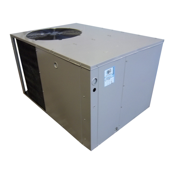
P3RX Series - Export Models
Single Package Air Conditioner
Read this owner information to become familiar with the capabilities and use of your appliance. Keep this with literature on
other appliances where you have easy access to it in the future. If a problem occurs, check the instructions and follow
recommendations given. If these suggestions don't eliminate your problem, call your installing contractor or distributor in
your area.
INTRODUCTION
Most any air conditioner will keep you cool. Our NORDYNE air conditioner was designed to do it efficiently. Efficiency means
less cost to you while keeping you comfortable.
WHY YOUR NORDYNE AIR CONDITIONER WORKS SO WELL, SO QUIETLY
1. Air is cooled by a large evaporator coil. Moisture is also removed from the air by this same coil.
2. Air is then delivered through the main duct, via registers, into your home.
3. Return air is drawn through the return register.
4. This air enters the unit, passes through the evaporator coil, is cooled and dehumidified. Then the cycle begins again.
Single Package Air Conditioner
IMPORTANT
Advertisement
Table of Contents

Subscribe to Our Youtube Channel
Related Manuals for Nordyne P3RX Series


Summary of Contents for Nordyne P3RX Series
- Page 1 INTRODUCTION Most any air conditioner will keep you cool. Our NORDYNE air conditioner was designed to do it efficiently. Efficiency means less cost to you while keeping you comfortable. WHY YOUR NORDYNE AIR CONDITIONER WORKS SO WELL, SO QUIETLY 1.
-
Page 2: Table Of Contents
TABLE OF CONTENTS Owner Information ..........................3 Operating Instructions ......................... 3 Before You Call A Serviceman ....................3 Installer Information .......................... 4 General ............................4 Pre-Installation Check ......................... 4 Installation ........................... 4 Ducting Systems ..........................6 Duct Requirements ........................6 Connecting Return and Air Supply Flexible Ducts .............. -
Page 3: Owner Information
SECTION 1. OWNER INFORMATION In addition, follow these simple rules: 1. Never run your system without filter. If you do, the cooling OPERATING INSTRUCTIONS coils will get dirty and may become clogged. 2. Set your thermostat at the comfort level you wish -- and To Turn On Air Conditioner then leave it alone. -
Page 4: Installer Information
SECTION 2. INSTALLER INFORMATION INSTALLATION 1. UNPACK THE UNIT GENERAL It is recommended that the unit be unpacked at the installation site to minimize damage due to handling. Read the following instructions completely before performing the installation. CAUTION: These instructions are for the use of qualified personnel Do not tip the unit on its side. - Page 5 Transition Duct Screws 14" Duct Dimples Supply Air Return Air Figure 3. Return and Supply Air Fittings Figure 4. Return Air Box Align the slots with the holes in the collar and install two 3. INSTALL THE RETURN AND SUPPLY AIR FITTINGS screws.
-
Page 6: Ducting Systems
5. LOCATING AND INSTALLING THE SUPPLY DUCTING SYSTEM DAMPER(S) (See Figure 5) DUCT REQUIREMENTS The supply duct system, including the number and type of CAUTION: registers, will have much more effect on the performance of an air conditioning system than any other factor. The duct When a home is not equipped with a make-ready must be sufficiently large to conduct an adequate amount of kit by the manufacturer, means must be provided... - Page 7 TYPICAL APPLICATIONS SINGLE WIDE APPLICATION DOUBLE WIDE APPLICATION Ref. No. Description 12" x 20" Return Air 16" x 20" Air Filter 12" x 20" Grille Supply Damper 12" or 14" Diameter Flex Return Duct 12" Diameter Flex Supply Duct 12" x 12" x 12" “Y” Fitting Figure 6.
-
Page 8: Condensate Drain
Elbow High Voltage Low Voltage P-Trap Figure 8. Power Entry Figure 7. Drain Trap The principal reason for specifying a time delay type is to CONDENSATE DRAIN (SEE FIGURE 7) prevent nuisance trips when the unit starts. A 3/4" condensate fitting extends out of the side of the unit. In the event that a fuse does blow or a breaker trips, always The drain trap, shipped in the electrical compartment, must be determine the reason. -
Page 9: System Operation
Figure 9. Low Voltage Connections connections and proper heat anticipator setting when 2. START-UP PROCEDURE installing unit with an external furnace. a. Set the system switch to the OFF position. SYSTEM OPERATION b. Dial thermostat setting as high as it will go. c. -
Page 10: Wiring Diagrams
703772B Figure 10. Single Phase Unit Wiring Diagram... -
Page 11: Three Phase
703809B Figure 10. Three Phase 380V/420V Unit Wiring Diagram... -
Page 12: Wiring Diagrams
703841B Figure 10. Three Phase 208/230V Unit Wiring Diagram... -
Page 13: Refrigerant Charging Tables
P3RX - Refrigerant Charging Tables 2 Ton 2 Ton OUTDOOR TEMPERATURE (°F) Suct. Press. Dis. Press. Dis. Temp. Dis. Press. Dis. Temp. Dis. Press. Dis. Temp. Dis. Press. Dis. Temp. Dis. Press. Dis. Temp. Dis. Press. Dis. Temp. Dis. Press. Dis. - Page 14 P3RX - Refrigerant Charging Tables 3-1/2 Ton 3-1/2 Ton OUTDOOR TEMPERATURE (°F) Suct. Press.Dis. Press. Dis. Temp. Dis. Press. Dis. Temp. Dis. Press. Dis. Temp. Dis. Press. Dis. Temp. Dis. Press. Dis. Temp. Dis. Press. Dis. Temp. Dis. Press. Dis. Temp. Dis. Press. Dis. Temp. 4 Ton 4 Ton OUTDOOR TEMPERATURE (°F)
- Page 16 INSTALLER PLEASE LEAVE THESE INSTALLATION INSTRUCTIONS WITH THE HOMEOWNER. 707633C (Replaces 707633B) Specifications and illustrations subject to change without notice and without incurring obligations. St. Louis, MO Printed in U.S.A. (4/99) 707633C...
Need help?
Do you have a question about the P3RX Series and is the answer not in the manual?
Questions and answers