Table of Contents
Advertisement
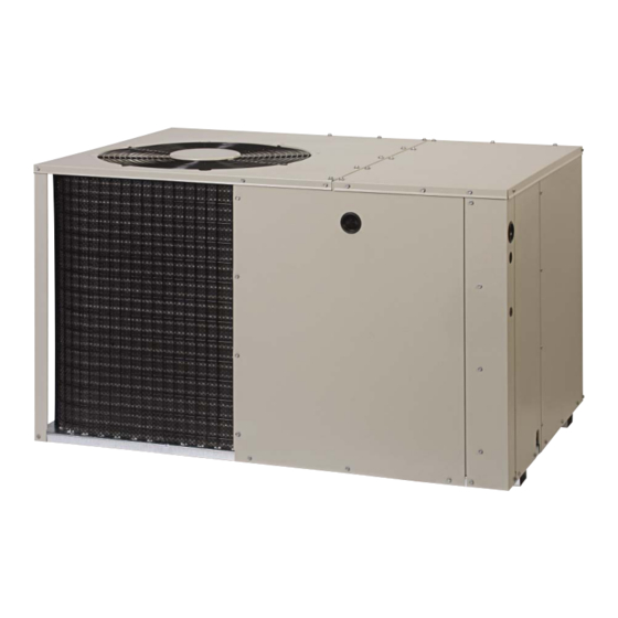
P3RA SERIES
USER's MANUAL & INSTALLATION INSTRUCTIONS
R-22 Single Package Air Conditioner
User, please read this information thoroughly and become familiar with the capabilities and
use of your appliance before attempting to operate or maintain this unit. Keep this literature
where you have easy access to it in the future. If a problem occurs, check the instructions and
follow recommendations given. If these suggestions don't eliminate your problem, call your
servicing contractor.
The Installation Instructions are primarily intended to assist qualifi ed individuals experienced
in the proper installation of this appliance. Some local codes require licensed installation/
service personnel for this type of equipment. Please read all instructions carefully before
starting the installation.
IMPORTANT
DO NOT DESTROY. PLEASE READ CAREFULLY AND
KEEP IN A SAFE PLACE FOR FUTURE REFERENCE.
10 SEER
Advertisement
Table of Contents

Related Manuals for Nordyne P3RA SERIES


Summary of Contents for Nordyne P3RA SERIES
- Page 1 P3RA SERIES 10 SEER USER’s MANUAL & INSTALLATION INSTRUCTIONS R-22 Single Package Air Conditioner IMPORTANT User, please read this information thoroughly and become familiar with the capabilities and use of your appliance before attempting to operate or maintain this unit. Keep this literature where you have easy access to it in the future.
-
Page 2: Table Of Contents
USER INFORMATION Important Safety Information ........3 WARRANTY INFORMATION Operating Instructions ..........3 A warranty certifi cate with full details is included with the Cooling Operation .............3 Air Conditioner. Carefully review these responsibilities with Heating Operation .............3 your dealer or service company. The manufacturer will not Turning the Air Conditioner Off ........3 be responsible for any costs found necessary to correct Operating the Indoor Blower Continuously ....3... -
Page 3: Important Safety Information
USER INFORMATION Turning the Air Conditioner OFF IMPORTANT SAFETY INFORMATION Change the thermostat’s system mode to OFF and the fan Safety markings are used to designate a degree or level mode to AUTO (See Figure 1). NOTE: The system will not of seriousness and should not be ignored. -
Page 4: Important Safety Information
INSTALLER INFORMATION IMPORTANT SAFETY INFORMATION CAUTION: Please read all instructions before servicing this equipment. Pay attention to all safety warnings and any other special This unit uses refrigerant R-22. DO NOT use notes highlighted in the manual. Safety markings are any other refrigerant in this unit. -
Page 5: General Information
GENERAL INFORMATION • Consideration should also be given to availability of electric power, service access, noise, and shade. The P3RA packaged air conditioner is designed only for outdoor ground level installations and can be readily Minimum Clearance Requirements connected to the high static duct system of a home. This unit Suffi... -
Page 6: Air Conditioner Installation
• All duct work passing through unconditioned space 4. Tap collar (if necessary) to ensure engagement with must be properly insulated to minimize duct losses unit opening and install second screw. and prevent condensation. Use insulation with an outer 5. Tighten fi rst screw and rotate collar clockwise so joint vapor barrier. -
Page 7: Locating & Installing The Supply Dampers
SINGLE DUCT APPLICATION MULTIPLE DUCT APPLICATION Figure 4. Single & Multiple Duct Applications Locating & Installing the Supply Damper(s) NOTE: In most installations it will be necessary to cut a similar hole in the fi berboard directly under the hole in CAUTION: the fl... -
Page 8: Condensate Drainage
Condensate Drainage ELECTRICAL CONNECTIONS A 3/4” condensate fi tting extends out of the side of the unit (Figure 3). The drain trap, shipped in the electrical WARNING: compartment, must be installed to prevent water from collecting inside the unit. To avoid risk of electrical shock, personal 1. -
Page 9: Overcurrent Protection
(Figures 12 & 13, pages 14 & 15)) for identifi cation and Unbalanced 3-Phase Supply Voltage location of unit fi eld wiring interfaces. Make all electrical Voltage unbalance occurs when the voltages of all phases connections in accordance with all applicable codes of a 3-phase power supply are no longer equal. -
Page 10: Thermostat / Low Voltage Connections
Thermostat / Low Voltage Connections If you have one thermostat for heating and another • The unit is designed to operate from a 24 VAC Class II for cooling, they must be interlocked to prevent control circuit. The control circuit wiring must comply with simultaneous operation. -
Page 11: Startup & Adjustments
START UP & ADJUSTMENTS System Cooling Before You Start the Unit Set the thermostat’s system mode to COOL and the The following check list should be observed prior to fan mode to AUTO. Change the thermostat temperature starting the unit. selector below the existing room temperature. -
Page 12: Air Conditioner Maintenance
• Inspect and clean or replace air fi lters at the beginning REPLACEMENT PARTS of each heating and cooling season, or more frequently Replacement parts are available through all Nordyne distributors. Please have the complete model and serial number of the unit if required. -
Page 13: Figures & Tables
FIGURES & TABLES Top View 9.15 1" 3.15 9.04 17.50 Electric Heater Power Supply 12" diameter 14" diameter Power Supply Supply Duct Return Duct Low Voltage Supply Opening Opening Back (Duct) View Control Blower Access Panel Access 17.86 Side View Panel 15.36 10.10... -
Page 14: Wiring Diagrams
WIRING DIAGRAMS Figure 12. P3RA - Single Phase with PSC Motor - 3, 4, & 5 Ton Models... - Page 15 WIRING DIAGRAMS - CONTINUED Figure 13. P3RA Wiring Diagram - 3 Phase with PSC Motor (5 Ton Models Only)
-
Page 16: Refrigerant Charging Charts
REFRIGERANT CHARGING CHARTS Refrigerant Charging Chart Legend: Shaded boxes indicate fl ooded conditions. Rated design values. The suction pressure will vary from design value if outdoor air fl ow, entering dry bulb, or entering wet bulb temperatures vary. 1. All pressures are listed psig and all temperatures in °F 2. -
Page 17: Blower Performance
REFRIGERANT CHARGING CHARTS - CONTINUED OUTDOOR TEMPERATURE 70° F 75° F 80° F 85° F 90° F 95° F 100° F 105° F Suct. Press. Dis. Dis. Dis. Dis. Dis. Dis. Dis. Dis. Dis. Dis. Dis. Dis. Dis. Dis. Dis. Dis. -
Page 20: Installation / Performance Checklist
INSTALLATION / PERFORMANCE CHECK LIST REFRIGERATION SYSTEM: INSTALLATION ADDRESS: Was unit given 24 hr warm up period for crankcase heaters (if installed)? CITY ________________________ STATE ________________ Stage-1 Liquid Pressure (high side) ________________________ UNIT MODEL # ________________________________________ Stage-1 Suction Pressure (low side) ________________________ UNIT SERIAL # ________________________________________ Has the owner’s information been Unit Installed Minimum clearances per...
Need help?
Do you have a question about the P3RA SERIES and is the answer not in the manual?
Questions and answers