Table of Contents
Advertisement
Quick Links
P6SD SERIES
USER'S MANUAL / INSTALLATION INSTRUCTIONS
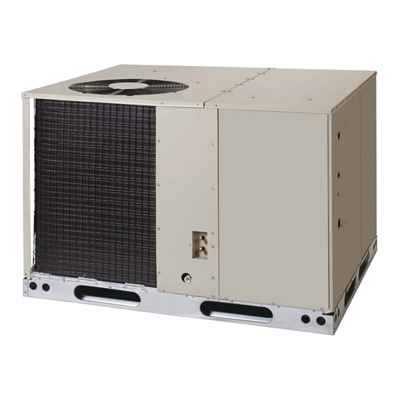
SINGLE PACKAGE CONVERTIBLE AIR CONDITIONER
Premium Model Shown
Please read this information thoroughly and become familiar with the capabilities and
use of your appliance before attempting to operate or maintain this unit. Keep this
literature where you have easy access to it in the future. If a problem occurs, check the
instructions and follow recommendations given. If these suggestions don't eliminate
your problem, call your servicing contractor.
These instructions are primarily intended to assist qualifi ed individuals experienced in
the proper installation of this appliance. Some local codes require licensed installation/
service personnel for this type of equipment. Please read all instructions carefully before
starting the installation.
IMPORTANT
DO NOT DESTROY. PLEASE READ CAREFULLY AND
KEEP IN A SAFE PLACE FOR FUTURE REFERENCE.
13 SEER
Advertisement
Table of Contents

Subscribe to Our Youtube Channel
Related Manuals for Nordyne P6SD Series


Summary of Contents for Nordyne P6SD Series
- Page 1 P6SD SERIES 13 SEER USER’S MANUAL / INSTALLATION INSTRUCTIONS SINGLE PACKAGE CONVERTIBLE AIR CONDITIONER Premium Model Shown IMPORTANT Please read this information thoroughly and become familiar with the capabilities and use of your appliance before attempting to operate or maintain this unit. Keep this literature where you have easy access to it in the future.
-
Page 3: Table Of Contents
USER INFORMATION Safety Information ............4 WARRANTY INFORMATION About the Air Conditioner .........4 A warranty certifi cate with full details is included with the Operating Instructions..........4 Air Conditioner. Carefully review these responsibilities with Cooling Operation .............4 your dealer or service company. The manufacturer will not Heating Operation .............4 be responsible for any costs found necessary to correct Turning the Air Conditioner Off .........4... -
Page 4: Safety Information
USER INFORMATION SAFETY INFORMATION IMPORTANT: Please read all instructions before servicing this equipment. Pay attention to all safety warnings and any other special notes highlighted in the manual. Safety markings are used frequently throughout this manual to designate a degree or level of seriousness and should not be ignored. -
Page 5: Safety Information
INSTALLER INFORMATION SAFETY INFORMATION WARNING: IMPORTANT: Safety markings are used frequently throughout this manual to designate a degree or level Do not place combustible material on or against of seriousness and should not be ignored. WARNING the unit cabinet. Do not place combustible indicates a potentially hazardous situation that if materials, including gasoline and any other not avoided, could result in personal injury or death. -
Page 6: General Information
GENERAL INFORMATION Locating the Air Conditioner • Survey the job site to determine the best location for Packaged Air Conditioner units are ready for easy and mounting the outdoor unit. immediate installation on rooftops or ground level slabs. • Choose an appropriate location that minimizes the Units are shipped for horizontal duct connections and length of the supply and return air ducts. -
Page 7: Air Filter Requirements
• Duct lining must be UL classifi ed batts or blankets with AIR CONDITIONER INSTALLATION a fi re hazard classifi cation of FHC-25/50 or less. Packaging Removal • Fiber duct work may be used in place of internal duct Remove the shipping carton and User’s Manual from liners if the fi... -
Page 8: Rooftop
Securing Screws 2” Figure 5. Internal Filter Rack Location Removal of Internal Filter Rack (3 Phase Only) Figure 3. Ground Level Installation 1. Remove the return air panel from the unit. Rooftop 2. Remove the height adjustment screw from the inside Rooftop installations must be located according to local of the rack. -
Page 9: Electrical Wiring
same size and prime with water. When connecting rigid switch shall be capable of electrically de-energizing the drain line, hold the female fi tting with a wrench to prevent outdoor unit. See unit data label for proper incoming fi eld twisting. -
Page 10: Unbalanced 3-Phase Supply Voltage
C22.1 Electrical Code. Use the grounding lug provided COPPER WIRE SIZE — AWG in the control box for grounding the unit. (1% Voltage Drop) Supply Wire Length-Feet Supply Circuit Unbalanced 3-Phase Supply Voltage Ampacity Voltage unbalance occurs when the voltages of all phases of a 3-phase power supply are no longer equal. -
Page 11: Psc Motor - 208/230V
The blower speed for 3 and 4 ton units is preset at the Fixed Torque ECM Motor factory for operation at the same speed for heating and 1. Shut off all electrical power to the unit and remove cooling. These factory settings are listed in Table 5 the blower panel. -
Page 12: Startup & System Check
START UP & SYSTEM CHECK System Heating If the unit has been equipped with optional electric heater Pre-Start Check List Verify the unit is level and allows condensate to drain. kits, set the thermostat's system mode to HEAT and the ... - Page 13 step 4, then there is too much charge in the system. Remove refrigerant and repeat steps 1 through 3 until the system is correctly charged. 5. If the pressure measured in step 1 is less than the required liquid refrigerant pressure determined in step 4, then there is too little charge in the system.
-
Page 14: Air Conditioner Maintenance
FIGURES & TABLES 24 9/10 3/4" NPT Female Drain Connector DOWNFLOW SUPPLY DUCT OPENING 47 1/2 13 1/2 13 1/2 13 3/10 23 1/2 DOWNFLOW RETURN DUCT OPENING Top View 1 4/5 1 3/4 Ø Power Entry (Capped) HORIZONTAL 1 1/4 Ø Power Entry SUPPLY DUCT CONDENSING OPENING... -
Page 15: Electrical Information
ELECTRICAL INFORMATION Brown Orange FROM BLOWER RELAY Green ACCESSORY HEAT PLUG FROM CONTACTOR ECONOMIZER PLUG Black (Optional, Check Gray Thermostat Instructions) Yellow Blue INDOOR FROM TRANSFORMER THERMOSTAT SUB-BASE Typical Wiring (Field Supplied) for 1-Stage Cool, 1-Stage Heat Optional Outdoor Thermostat (Field Supplied) Brown Orange... - Page 16 ACCESSORY HEAT PLUG Brown Orange FROM BLOWER RELAY Green 24V Common FROM CONTACTOR ECONOMIZER PLUG Black (Optional, Check Gray Thermostat Instructions) Yellow Blue FROM TRANSFORMER INDOOR THERMOSTAT SUB-BASE Figure 11. Typical Air Conditioner Thermostat Connections - 460V External Static Pressure Drop - inches water column Model Number P6SD - High...
- Page 17 Figure 12. Wiring Diagram-PSC Motor, Three Phase...
- Page 18 Figure 13. Wiring Diagram-Fixed Torque Motor, Three Phase...
- Page 19 Figure 14. Wiring Diagram-PSC Motor, Single Phase...
- Page 20 Figure 15. Wiring Diagram-Fixed Torque Motor, Single Phase...
- Page 21 Figure 16. Wiring Diagram-Fixed Torque Motor, Three Phase - 460V...
- Page 22 Figure 17. Wiring Diagram-PSC Motor, Three Phase - 460V...
-
Page 23: Cooling Charging Charts
COOLING CHARGING CHARTS - 14 SEER A.C. P6SD-X36 Charging Chart - Cooling Remove refrigerant when above curve Add refrigerant when below curve Liquid Temperature (° F) Figure 18. Charging Chart for 3 Ton Units P6SD-X48 Charging Chart - Cooling Remove refrigerant when above curve Add refrigerant when below curve Liquid Temperature (°... - Page 24 COOLING CHARGING CHARTS - 13 SEER A.C. (CONTINUED) P6SD-X60 Charging Chart - Cooling Remove refrigerant when above curve Add refrigerant when below curve Liquid Temperature (° F) Figure 20. Charging Chart for 2 Ton Units INSTALLER PLEASE LEAVE THESE INSTALLATION INSTRUCTIONS WITH THE HOMEOWNER.
Need help?
Do you have a question about the P6SD Series and is the answer not in the manual?
Questions and answers