Table of Contents
Advertisement
Quick Links
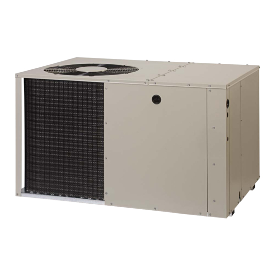
P5RF SERIES
USER's MANUAL & INSTALLATION INSTRUCTIONS
Single Package Air Conditioner - 2 Stage, R410A
Please read this information thoroughly and become familiar with the capabilities and use of
your appliance before attempting to operate or maintain this unit. Keep this literature where
you have easy access to it in the future. If a problem occurs, check the instructions and
follow recommendations given. If these suggestions don't eliminate your problem, call your
servicing contractor.
The Installation Instructions are primarily intended to assist qualifi ed individuals experienced
in the proper installation of this appliance. Some local codes require licensed installation/
service personnel for this type of equipment. Please read all instructions carefully before
starting the installation.
IMPORTANT
DO NOT DESTROY. PLEASE READ CAREFULLY AND
KEEP IN A SAFE PLACE FOR FUTURE REFERENCE.
15 SEER
Advertisement
Table of Contents

Subscribe to Our Youtube Channel
Related Manuals for Nordyne P5RF Series


Summary of Contents for Nordyne P5RF Series
- Page 1 P5RF SERIES 15 SEER USER’s MANUAL & INSTALLATION INSTRUCTIONS Single Package Air Conditioner - 2 Stage, R410A IMPORTANT Please read this information thoroughly and become familiar with the capabilities and use of your appliance before attempting to operate or maintain this unit. Keep this literature where you have easy access to it in the future.
-
Page 3: Table Of Contents
USER INFORMATION Important Safety Information ........4 WARRANTY INFORMATION Operating Instructions ..........4 A warranty certifi cate with full details is included with the Cooling Operation .............4 air conditioner. Carefully review these responsibilities with Heating Operation .............4 your dealer or service company. The manufacturer will not Turning the Air Conditioner Off ........4 be responsible for any costs found necessary to correct Operating the Indoor Blower Continuously ....4... -
Page 4: Important Safety Information
USER INFORMATION Turning the Air Conditioner OFF IMPORTANT SAFETY INFORMATION Change the thermostat’s system mode to OFF and the fan Safety markings are used to designate a degree or level mode to AUTO (See Figure 1). NOTE: The system will not of seriousness and should not be ignored. -
Page 5: Important Safety Information
INSTALLER INFORMATION IMPORTANT SAFETY INFORMATION CAUTION: Please read all instructions before servicing this equipment. Pay attention to all safety warnings and any other special This unit uses refrigerant R-410A. DO NOT notes highlighted in the manual. Safety markings are use any other refrigerant in this unit. Use used frequently throughout this manual to designate a of another refrigerant will damage the unit. -
Page 6: General Information
GENERAL INFORMATION • Suffi cient clearance for unobstructed airfl ow through the outdoor coil must be maintained in order to achieve The P5RF air conditioner is designed only for outdoor rated performance. ground level installations and can be readily connected •... -
Page 7: Air Conditioner Installation
SINGLE DUCT APPLICATION MULTIPLE DUCT APPLICATION Figure 3. Single & Multiple Duct Applications • Duct work should be attached directly to the unit AIR CONDITIONER INSTALLATION fl anges for horizontal applications. Unpacking the Unit • For highly resistive duct systems it may be necessary It is recommended that the unit be unpacked at the to add an additional return air duct and or supply to installation site to minimize damage due to handling. -
Page 8: Locating & Installing The Return Air Assembly
4. Tap collar (if necessary) to ensure engagement with unit opening and install second screw. Elbow 5. Tighten fi rst screw and rotate collar clockwise so joint is near three o’clock position. Return Duct 1. Assemble the collar by overlapping the two ends. NOTE: One end of the collar is slotted and the opposite end has two small holes. -
Page 9: Grounding
• Line voltage to the unit should be supplied from a Grounding dedicated branch circuit containing the correct fuse WARNING: or circuit breaker for the unit. Incoming fi eld wiring and minimum size of electrical conductors and circuit The unit cabinet must have an uninterrupted protection must be in compliance with information or unbroken electrical ground to minimize listed on the unit data label. -
Page 10: Thermostat / Low Voltage Connections
Thermostat / Low Voltage Connections where its operation may be adversely affected by The 15 SEER air conditioner uses a special two speed radiant heat from fi replaces, sunlight, or lighting compressor to achieve a high level of effi ciency in a fi... -
Page 11: Cooling Mode
Cooling Mode Blower Speed 1. On a call for cooling, the thermostat closes, and For optimum system performance and comfort, it may be applies 24VAC to the G & Y1 terminals of the control. necessary to change the factory speed setting. See Table The compressor contactor closes and operates the 3 for factory settings. -
Page 12: Startup & Adjustments
START UP & ADJUSTMENTS Emergency Heat (Available only when Electric heat is supplied) Pre-Start Checklist 1. Set the thermostat’s system mode to EM HT and the The following check list should be observed prior to fan mode to either AUTO (intermittent air) or to ON starting the unit. -
Page 13: Air Conditioner Maintenance
REPLACEMENT PARTS • Inspect the condensate drain and outdoor coil at the Replacement parts are available through all Nordyne beginning of each cooling season. Remove any debris. distributors. Please have the complete model and serial Clean the outdoor coil and louvers as necessary using number of the unit when ordering replacement parts. -
Page 14: Figures & Tables
FIGURES & TABLES Top View 9.15 1" 3.15 9.04 17.50 Electric Heater Power Supply 12" diameter 14" diameter Power Supply Supply Duct Return Duct Low Voltage Supply Opening Opening Back (Duct) View Control Blower Access Panel Access 17.86 Side View Panel 15.36 10.10... -
Page 15: Refrigerant Charging Charts
REFRIGERANT CHARGING CHARTS P5RF-X24K Charging Chart - Cooling Remove refrigerant when above curve Add refrigerant when below curve Liquid Temperature (F) Figure 9. Charging Chart for 2 ton Units P5RF-X36K Charging Chart - Cooling Remove refrigerant when above curve Add refrigerant when below curve Liquid Temperature (F) Figure 10. - Page 16 REFRIGERANT CHARGING CHARTS - CONTINUED P5RF-X48K Charging Chart - Cooling Remove refrigerant when above curve Add refrigerant when below curve Liquid Temperature (F) Figure 11. Charging Chart for 4 ton Units P5RF-X60K Charging Chart - Cooling Remove refrigerant when above curve Add refrigerant when below curve Liquid Temperature (F) Figure 12.
-
Page 17: Wiring Diagrams
WIRING DIAGRAMS Figure 13. P5 Series Wiring Diagram - 2 & 3 Ton Units... - Page 18 Figure 14. P5 Series Wiring Diagram - 4 & 5 Ton Units...
-
Page 20: Installation / Performance Checklist
INSTALLATION / PERFORMANCE CHECK LIST REFRIGERATION SYSTEM: INSTALLATION ADDRESS: Was unit given 24 hr warm up period for crankcase heaters (if applicable)? CITY ______________________ STATE _________________ Stage-1 Liquid Pressure (high side) ________________________ UNIT MODEL # ________________________________________ Stage-1 Suction Pressure (low side) ________________________ UNIT SERIAL # _______________________________________ Has the owner’s information been Unit Installed Minimum clearances...
Need help?
Do you have a question about the P5RF Series and is the answer not in the manual?
Questions and answers