Chapters
Table of Contents

Related Manuals for Stahl 9478 Series


Summary of Contents for Stahl 9478 Series
- Page 1 Betriebsanleitung Additional languages www.r-stahl.com Digital Output Modul Ventil für Zone 1 Reihe 9478...
-
Page 2: Table Of Contents
Inhaltsverzeichnis Allgemeine Angaben ...................3 Hersteller ......................3 Angaben zur Betriebsanleitung ................3 Weitere Dokumente ....................3 Konformität zu Normen und Bestimmungen ............3 Erläuterung der Symbole ..................3 Symbole in der Betriebsanleitung ...............3 Warnhinweise .....................4 Symbole am Gerät ....................4 Sicherheitshinweise ....................5 Aufbewahrung der Betriebsanleitung ..............5 Qualifikation des Personals ................5 Sichere Verwendung ...................5 Umbauten und Änderungen ................7... -
Page 3: De De De
2018-11-06·BA00·III·de·04 Die Originalbetriebsanleitung ist die englische Ausgabe. Diese ist rechtsverbindlich in allen juristischen Angelegenheiten. Weitere Dokumente • Kopplungsbeschreibung IS1 (Download unter www.r-stahl.com) • Datenblatt Dokumente in weiteren Sprachen, siehe www.r-stahl.com. Konformität zu Normen und Bestimmungen Zertifikate und EU-Konformitätserklärung, siehe www.r-stahl.com. -
Page 4: De 2.2 Warnhinweise
Erläuterung der Symbole Warnhinweise Warnhinweise unbedingt befolgen, um das konstruktive und durch den Betrieb bedingte Risiko zu minimieren. Die Warnhinweise sind wie folgt aufgebaut: • Signalwort: GEFAHR, WARNUNG, VORSICHT, HINWEIS • Art und Quelle der Gefahr/des Schadens • Folgen der Gefahr •... -
Page 5: Sicherheitshinweise
Normen und Bestimmungen umfasst. Für Tätigkeiten in explosionsgefährdeten Bereichen sind weitere Kenntnisse erforderlich! R. STAHL empfiehlt einen Kenntnisstand, der in folgenden Normen beschrieben wird: • IEC/EN 60079-14 (Projektierung, Auswahl und Errichtung elektrischer Anlagen) • IEC/EN 60079-17 (Prüfung und Instandhaltung elektrischer Anlagen) •... - Page 6 Sicherheitshinweise Bei Montage und Installation • Montage und Installation nur durch qualifizierte und autorisierte Personen (siehe Kapitel "Qualifikation des Personals") durchführen lassen. • Gerät nur in Bereichen installieren, für die es aufgrund seiner Kennzeichnung geeignet ist. • Bei Installation und im Betrieb die Angaben (Kennwerte und Bemessungsbetriebs- bedingungen) auf Typ- und Datenschildern sowie die Hinweisschilder am Gerät beachten.
-
Page 7: Umbauten Und Änderungen
Funktion und Geräteaufbau Inbetriebnahme, Wartung, Reparatur • Inbetriebnahme und Instandsetzung nur durch qualifizierte und autorisierte Personen (siehe Kapitel "Qualifikation des Personals") durchführen lassen. • Vor Inbetriebnahme sicherstellen, dass das Gerät unbeschädigt ist. • Nur Wartungsarbeiten durchführen, die in dieser Betriebsanleitung beschrieben sind. •... -
Page 8: De Funktion
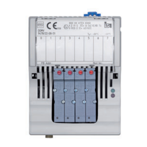
Funktion und Geräteaufbau Funktion Einsatzbereich Das Digital Output Modul mit Ventil Typ 9478 ist eine Systemkomponente des Remote I/O Systems IS1+ zur Ansteuerung von pneumatischen Steuerkreisen. Das Gerät ist ein eigensicheres elektrisches Betriebsmittel der Schutzart Ex ib. Das Gerät kann, bei Einbau in ein entsprechend geeignetes Gehäuse, in gas- und staubexplosionsgefährdeten Bereichen der Zonen 1, 2, 21 und der Zone 22 oder im sicheren Bereich eingesetzt werden. -
Page 9: Technische Daten
Technische Daten Technische Daten Explosionsschutz Global (IECEx) IECEx PTB 06.0001X Ex ib IIC T4 Europa (ATEX) PTB 10 ATEX 2030 E II 2 G Ex ib IIC T4 Gb Bescheinigungen und Zertifikate Bescheinigungen IECEx, ATEX, EAC (TR), Brasilien (INMETRO), USA/Kanada (cFMus) Schiffszertifikate EU RO Mutual Recognition (inkl. - Page 10 Technische Daten Technische Daten Elektrische Daten Digital-Eingang Ex i Funktion Anlagen-AUS, Ausgänge werden drucklos geschaltet Versorgungs- spannung Innenwiderstand 1,6 kΩ Maximale 1,6 kΩ für Ausgänge im Normalbetrieb Spannung Minimale 3,5 V für alle Ausgänge drucklos geschaltet ("Anlagen-AUS") Spannung Einstellungen Drahtbruch-/ Kurzschluss- überwachung Sicherheits-...
- Page 11 • Hardwareabschaltung Ausgang (durch "Anlagen-AUS") Montage / Installation Einbaulage waagrecht oder senkrecht (Betriebsanleitung beachten) Montageart auf 35-mm-DIN-Schiene NS 35/15 (DIN EN 60715) Weitere technische Daten, siehe www.r-stahl.com. 205343 / 947860310010 Digital Output Modul Ventil für Zone 1 2018-11-06·BA00·III·de·04 Reihe 9478...
-
Page 12: Projektierung
Projektierung Projektierung HINWEIS Ausfall der installierten Geräte im Schaltschrank durch zu hohe Umgebungstemperatur! Nichtbeachten kann zu Sachschäden führen. • Schaltschrank so aufbauen und einrichten, dass er immer innerhalb des zulässigen Temperaturbereichs betrieben wird. Bei der Projektierung folgende Bedingungen beachten: • In der Abdeckklappe befindet sich ein Einlegeschild, in das die Zuordnung der Feldgeräte zu den Kanälen eingetragen werden kann. -
Page 13: Anschlussbelegung Steckbare Klemme X2
Transport und Lagerung Anschlussbelegung 14465E00 Kanal Nr. Ansteuerung Steuerkreis Kanal Nr. Ansteuerung Steuerkreis Wirkungsweise 14466E00 3/2-Wege-Magnetventil, vorgesteuert Schaltzustand Funktion Ruhestellung (1) Druckanschluss (P) gesperrt Ausgang (Y0) entlüftet betätigt (2) Druck liegt an Ausgang (Y0) an Anschlussbelegung steckbare Klemme X2 Die Module haben eine steckbare Klemme X2 zum Anschluss an den Stromkreis "Anlagen-AUS". -
Page 14: Montage Und Installation
Montage und Installation Montage und Installation Das Gerät ist für den Einsatz in gasexplosionsgefährdeten Bereichen der Zonen 1 und 2, in staubexplosionsgefährdeten Bereichen der Zonen 21 und 22 sowie auch im sicheren Bereich zugelassen. GEFAHR Explosionsgefahr bei Installation ohne Feldgehäuse! Nichtbeachten führt zu schweren oder tödlichen Verletzungen! •... -
Page 15: Montage / Demontage, Gebrauchslage
Montage und Installation Montage / Demontage, Gebrauchslage 8.2.1 Montage / Demontage auf BusRail HINWEIS Fehlfunktion oder Geräteschaden durch unsachgemäße Montage. Nichtbeachten kann Sachschaden verursachen! • Gerät nur in senkrechter Lage, mit Pneumatik-Anschlüssen unten, links oder rechts, montieren und betreiben! (Orientierung horizontal: Lese-Richtung von unten) Montage auf BusRail •... - Page 16 Montage und Installation 8.2.2 Demontage / Modulwechsel GEFAHR Explosionsgefahr durch Entfernen druckbeaufschlagter Leitungen und Ventile! Nichtbeachten führt zu schweren oder tödlichen Verletzungen. • Vor dem Entfernen von Leitungen und Ventilen Leitungen drucklos machen und entlüften! • Nach Unterbrechung der elektrischen oder pneumatischen Versorgung einen kontrollierten Wiederanlauf des Prozesses gewährleisten.
-
Page 17: Installation
Inbetriebnahme Installation Bei Betrieb unter erschwerten Bedingungen wie insbesondere auf Schiffen sind zusätzliche Maßnahmen zur korrekten Installation je nach Einsatzort zu treffen. Weitere Informationen und Anweisungen hierzu erhalten Sie gerne auf Anfrage von Ihrem zuständigen Vertriebskontakt. In der Abdeckklappe befindet sich ein Einlegeschild, in das die Zuordnung der Feldgeräte zu den Kanälen eingetragen werden kann. -
Page 18: De 10.1 Betrieb
Betrieb Betrieb 10.1 Betrieb Normalbetrieb Im Normalbetrieb werden die Pneumatik-Anschlüsse über das IS1+ System angesteuert. Handbetätigung Die Pneumatik-Anschlüsse können einzeln manuell betätigt werden. • Handbetätigung für Y1, Y3, Y5, Y7: rastend • Handbetätigung für Y0, Y2, Y4, Y6: tastend oder rastend •... -
Page 19: Fehlerbeseitigung
I/O-Modul richtig auf BusRail aufrasten. • I/O-Modul tauschen. Wenn sich der Fehler mit den genannten Vorgehensweisen nicht beheben lässt: • An R. STAHL Schaltgeräte GmbH wenden. Zur schnellen Bearbeitung folgende Angaben bereithalten: • Typ und Seriennummer des Geräts • DCS/SPS • Protokoll •... -
Page 20: Instandhaltung, Wartung, Reparatur
11.3 Reparatur GEFAHR Explosionsgefahr durch unsachgemäße Reparatur! Nichtbeachten führt zu schweren oder tödlichen Verletzungen. • Reparaturen an den Geräten ausschließlich durch R. STAHL Schaltgeräte GmbH ausführen lassen. Digital Output Modul Ventil für Zone 1 205343 / 947860310010 Reihe 9478 2018-11-06·BA00·III·de·04... -
Page 21: Rücksendung
Reinigung 11.4 Rücksendung • Rücksendung bzw. Verpackung der Geräte nur in Absprache mit R. STAHL durchführen! Dazu mit der zuständigen Vertretung von R. STAHL Kontakt aufnehmen. Für die Rücksendung im Reparatur- bzw. Servicefall steht der Kundenservice von R. STAHL zur Verfügung. - Page 23 Operating instructions Additional languages www.r-stahl.com Digital Output Module Valve for Zone 1 Series 9478...
- Page 24 Contents General Information ....................3 Manufacturer .......................3 Information regarding the Operating Instructions ..........3 Further Documents .....................3 Conformity with Standards and Regulations ............3 Explanation of the Symbols ................3 Symbols in these Operating Instructions ............3 Warning Notes ....................4 Symbols on the Device ..................4 Safety Notes .......................5 Operating Instructions Storage ................5 Personnel Qualification ..................5...
-
Page 25: En En En
• Data sheet For documents in additional languages, see www.r-stahl.com. Conformity with Standards and Regulations See certificates and EU Declaration of Conformity: www.r-stahl.com. The device has IECEx approval. For certificate please refer to the IECEx homepage: http://iecex.iec.ch/ Further national certificates can be downloaded via the following link: https://r-stahl.com/en/global/products/support/downloads/. -
Page 26: En 2.2 Warning Notes
Explanation of the Symbols Warning Notes Warnings must be observed under all circumstances, in order to minimize the risk due to construction and operation. The warning notes have the following structure: • Signalling word: DANGER, WARNING, CAUTION, NOTICE • Type and source of danger/damage •... -
Page 27: Safety Notes
• Use the device in accordance with its intended and approved purpose only. • Always consult with R. STAHL Schaltgeräte GmbH if using the device under operating conditions which are not covered by the technical data. • Before installation, make sure that the device is not damaged. - Page 28 Safety Notes For mounting and installation • Have mounting and installation performed only by qualified and authorised persons (see chapter "Qualification of the personnel"). • The device is only to be installed in areas for which it is suited based on its marking. •...
-
Page 29: Modifications And Alterations
Function and Device Design Commissioning, maintenance, repair • Only have commissioning and repairs performed by qualified and authorised persons (see chapter "Personnel qualification"). • Before commissioning, make sure that the device is not damaged. • Perform only maintenance work described in these operating instructions. •... -
Page 30: En 4.1 Function
Function and Device Design Function Application range The digital output module with valve type 9478 is a system component of the IS1+ Remote I/O system for controlling the pneumatic control circuits. The device is intrinsically safe electrical equipment with an Ex ib degree of protection. Upon installation in a suitable enclosure, the device can used in gas and dust hazardous areas of Zones 1, 2, 21 and 22 or in safe areas. -
Page 31: Technical Data
Technical Data Technical Data Explosion Protection Global (IECEx) IECEx PTB 06.0001X Ex ib IIC T4 Europe (ATEX) PTB 10 ATEX 2030 E II 2 G Ex ib IIC T4 Gb Certifications and certificates Certificates IECEx, ATEX, EAC (TR), Brazil (INMETRO), USA/Canada (cFMus) Ship approval EU RO Mutual Recognition (including ABS, CCS, DNV GL, RINA, RS) Further parameters... - Page 32 Technical Data Technical Data Electrical data Ex i digital input Functions System OFF, outputs are depressurised Supply voltage Internal resistance 1.6 kΩ Maximum voltage 1.6 kΩ for outputs in normal operation Minimal voltage 3.5 V for all outputs are depressurised ("System OFF") Settings Open-circuit / short-circuit...
- Page 33 Mounting / Installation Mounting orientation Horizontal or vertical (observe operating instructions) Mounting type on 35 mm DIN rail NS 35/15 (DIN EN 60715) For further technical data, see www.r-stahl.com. 205343 / 947860310010 Digital Output Module Valve for Zone 1 2018-11-06·BA00·III·en·04 Series 9478...
-
Page 34: Engineering
Engineering Engineering NOTICE An ambient temperature that is too high may cause failure of the devices installed in the cabinet. Non-compliance can result in material damage. • Install and adjust the cabinet in such a way that it is always operated within the permissible temperature range. -
Page 35: Terminal Assignment Of The Pluggable Terminal X2
Transport and Storage Terminal assignment 14465E00 Channel No. Control Control circuit Channel No. Control Control circuit Mode of operation 14466E00 3/2-way solenoid valve, pilot-controlled Switching state Function Idle position (1) Pressure connection (P) disabled Output (Y0) bled Actuated (2) There is pressure at the output (Y0) Terminal Assignment of the pluggable Terminal X2 The modules have a pluggable terminal X2 to connect to the "System OFF"... -
Page 36: Mounting And Installation
Mounting and Installation Mounting and Installation The device is approved for use in gas explosion hazardous areas of Zones 1 and 2 and dust explosion hazardous area of Zones 21 and 22 and in safe areas. DANGER Explosion hazard due to installation without field enclosure! Non-compliance results in severe or fatal injuries! •... -
Page 37: Mounting / Dismounting, Operating Position
Mounting and Installation Mounting / Dismounting, Operating Position 8.2.1 Mounting / Dismounting on BusRail NOTICE Malfunction or device damage caused by improper mounting. Non-compliance may lead to material damage! • Install and operate the device only in a vertical position with bottom, left or right pneumatic connections (horizontal orientation: Reading direction from below) Mounting on BusRail... - Page 38 Mounting and Installation 8.2.2 Dismounting / Replacement of the Module DANGER Explosion hazard due to removing pressurised conductors and valves! Non-compliance results in severe or fatal injuries. • Depressurise and bleed the conductors and valves before removing them! • After interrupting the electrical or pneumatic power supply, ensure that the process is resumed in a controlled manner.
-
Page 39: Installation
Commissioning Installation Operation under difficult conditions, such as, in particular, on ships, requires additional measures to be taken for correct installation, depending on the place of use. Further information and instructions on this can be obtained from your regional sales contact on request. The cover flap features an insert disc which can be used to enter the assignment of the field devices to the channels. -
Page 40: En 10.1 Operation
Operation Operation 10.1 Operation Normal operation In normal operation, the pneumatic connections are actuated by the IS1+ system. Manual actuation The pneumatic connections can be manually actuated individually. • Manual actuation for Y1, Y3, Y5, Y7: latching • Manual actuation for Y0, Y2, Y4, Y6: spring return or latching •... -
Page 41: Troubleshooting
BusRail. • Replace the I/O module. If the error cannot be eliminated using the specified procedures: • Contact R. STAHL Schaltgeräte GmbH. For rapid processing, have the following information ready: • Type and serial number of the device • DCS/PLC •... -
Page 42: Maintenance, Overhaul, Repair
Explosion hazard due to improper repair! Non-compliance results in severe or fatal injuries. • Repair work on the devices must be performed only by R. STAHL Schaltgeräte GmbH. Digital Output Module Valve for Zone 1 205343 / 947860310010 Series 9478... -
Page 43: Returning The Device
• Only return or package the devices after consulting R. STAHL! Contact the responsible representative from R. STAHL. R. STAHL's customer service is available to handle returns if repair or service is required. • Contact customer service personally. • Go to the www.r-stahl.com website. - Page 45 Nonhazardous The Type 9478/22-08-51 Digital Output Module with valves is Class I, II, III, Division 1, Group A-G designed to receive a digital signal from the IS1 CPU & Power Module or Class I, Zone 1, Group IIC/IIB and control up to 8 pneumatic valves. The module is intrinsically safe for installation in a Class I, II, III, and also Division 1, Group A-G or Class I, Zone 1, Group IIC/IIB and also Class...
Need help?
Do you have a question about the 9478 Series and is the answer not in the manual?
Questions and answers