Chapters
Table of Contents

Subscribe to Our Youtube Channel
Related Manuals for Stahl 9482/32 Series


Summary of Contents for Stahl 9482/32 Series
- Page 1 Betriebsanleitung Additional languages www.r-stahl.com Temperatur Input Modul Zone 1 Reihe 9482/32...
-
Page 2: Table Of Contents
Inhaltsverzeichnis Allgemeine Angaben ...................3 Hersteller ......................3 Angaben zur Betriebsanleitung ................3 Weitere Dokumente ....................3 Konformität zu Normen und Bestimmungen ............3 Erläuterung der Symbole ..................3 Symbole in der Betriebsanleitung ...............3 Warnhinweise .....................4 Symbole am Gerät ....................4 Sicherheitshinweise ....................5 Aufbewahrung der Betriebsanleitung ..............5 Qualifikation des Personals ................5 Sichere Verwendung ...................5 Umbauten und Änderungen ................7... -
Page 3: De De
2018-07-03·BA00·III·de·02 Die Originalbetriebsanleitung ist die englische Ausgabe. Diese ist rechtsverbindlich in allen juristischen Angelegenheiten. Weitere Dokumente • Kopplungsbeschreibung IS1 (Download unter www.r-stahl.com) • Datenblatt Dokumente in weiteren Sprachen, siehe www.r-stahl.com. Konformität zu Normen und Bestimmungen Zertifikate und EU-Konformitätserklärung, siehe www.r-stahl.com. -
Page 4: 2.2 Warnhinweise
Erläuterung der Symbole Warnhinweise Warnhinweise unbedingt befolgen, um das konstruktive und durch den Betrieb bedingte Risiko zu minimieren. Die Warnhinweise sind wie folgt aufgebaut: • Signalwort: GEFAHR, WARNUNG, VORSICHT, HINWEIS • Art und Quelle der Gefahr/des Schadens • Folgen der Gefahr •... -
Page 5: Sicherheitshinweise
Normen und Bestimmungen umfasst. Für Tätigkeiten in explosionsgefährdeten Bereichen sind weitere Kenntnisse erforderlich! R. STAHL empfiehlt einen Kenntnisstand, der in folgenden Normen beschrieben wird: • IEC/EN 60079-14 (Projektierung, Auswahl und Errichtung elektrischer Anlagen) • IEC/EN 60079-17 (Prüfung und Instandhaltung elektrischer Anlagen) •... - Page 6 Sicherheitshinweise • Stromkreise der Zündschutzart "Ex i", die mit Stromkreisen anderer Zündschutzarten betrieben wurden, dürfen danach nicht mehr als Stromkreise der Zündschutzart "Ex i" betrieben werden. • Das Gerät ist für den Einsatz in gas-explosionsgefährdeten Bereichen der Zone 1, der Zone 2 und im sicheren Bereich zugelassen. •...
-
Page 7: Umbauten Und Änderungen
Funktion und Geräteaufbau Umbauten und Änderungen GEFAHR Explosionsgefahr durch Umbauten und Änderungen am Gerät! Nichtbeachten führt zu schweren oder tödlichen Verletzungen. • Gerät nicht umbauen oder verändern. Für Schäden, die durch Umbauten und Änderungen entstehen, besteht keine Haftung und keine Gewährleistung. Funktion und Geräteaufbau GEFAHR Explosionsgefahr durch zweckentfremdete Verwendung! -
Page 8: Geräteaufbau
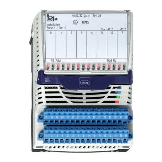
Funktion und Geräteaufbau Das Temperatur Input Modul Typ 9482/32 ist kompatibler Ersatz für IS1 Remote I/O-Module der Reihen 9480/12 und 9481/12. Geräteaufbau Gerätelement Beschreibung Abdeckung Abdeckung mit Einlegeschild (geöffnet) und Anschlussplan Beschriftung Angaben zum Modul (Seriennummer, Hardware-Revisionsnummer, Software-Revisionsnummer, Herstelldatum, z.B.: 12345678914-004; Rev. A; 01-01; 0514) LEDs LEDs (rot) zur Fehleranzeige (Drahtbruch/Kurzschluss) je Kanal... -
Page 9: Technische Daten
Technische Daten Technische Daten Explosionsschutz Global (IECEx) Gas und Staub IECEx DEK 13.0046X Ex ia [ia Ga] IIC T4 Gb [Ex ia Da] IIIC Europa (ATEX) Gas und Staub DEKRA 13 ATEX 0140 X E II 2 (1) G Ex ia [ia Ga] IIC T4 Gb E II (1) D [Ex ia Da] IIIC Bescheinigungen und Zertifikate Bescheinigungen... - Page 10 Technische Daten Technische Daten Anschließbare Referenz Messbereich Mittlere Widerstands- (ITS-90) Auflösung thermometer / Pt100 IEC 60751 -200 ... +850 °C 0,1 K Widerstands- geber Pt500 IEC 60751 -200 ... +850 °C 0,1 K Pt1000 IEC 60751 -200 ... +850 °C 0,1 K Ni100 DIN 43760...
- Page 11 Technische Daten Technische Daten Thermoelemente / mV-Geber Anzahl Kanäle Betriebsarten 8 Kanal genau / 4 Kanal schnell Anschlussart 2-Leiterschaltung Signalbereich -10 … +100 mV Linearität (para- temperaturlinear / spannungslinear metrierbar) Hinweis Alle Angaben in % des Messbereichs bei 23 °C Anschließbare Referenz Messbereich...
- Page 12 Technische Daten Technische Daten Messgenauigkeit intern: 0,025% / extern: abhängig vom Sensortyp, siehe "Anschließbare Widerstandsthermometer" Auflösung 0,1 K Temperaturabweichung ± 2 K bei Thermoelementen mit interner Kompensation Galvanische Trennung Prüfspannung gemäß Norm EN 60079-11 Zwischen Hilfsenergie / ) 1500 V AC Systemkomponenten Zwischen zwei I/O-Modulen ) 500 V AC...
-
Page 13: Projektierung
Montage / Installation Einbaubedingungen Montageart auf 35 mm DIN-Schiene NS 35/15 (DIN EN 60715) Einbaulage waagrecht oder senkrecht (Betriebsanleitung beachten) Weitere technische Daten, siehe www.r-stahl.com. Projektierung HINWEIS Ausfall der installierten Geräte im Schaltschrank durch zu hohe Umgebungstemperatur! Nichtbeachten kann zu Sachschäden führen. -
Page 14: Anschlussbelegung
Projektierung Bei der Projektierung folgende Bedingungen beachten: • Installation des Geräts zur bestimmungsgemäßen Verwendung nur auf der IS1 BusRail 9494. • Drei zulässige Montagelagen für der Betrieb des Geräts: siehe Kapitel "Montage / Demontage auf BusRail". • Module mit eigensicheren und nicht-eigensicheren Feldstromkreisen dürfen auf der BusRail gemischt betrieben werden. -
Page 15: Nachweis Der Eigensicherheit
Projektierung Die Signaleingänge sind untereinander galvanisch verbunden. Da sie als Differenzeingänge ausgelegt sind, werden Erdschleifen bei geerdeten Thermoelementen wirksam unterbunden. Optional können nicht verwendete Kanäle mit Widerständen (einfaches elektrisches Betriebsmittel für eigensichere Stromkreise gemäß EN 60079-11) bestückt werden um die Störmeldungen der jeweiligen Kanäle zu unterdrücken. - Page 16 Projektierung 6.2.1 Flussdiagramm zur Auswahl der sicherheitstechnischen Daten 16556E00 Legende = Widerstandsthermometer und / oder Widerstandsferngeber = Thermoelemente und / oder mV-Geber Ext. / Int. CJC = externe / interne Vergleichsstelle ungrounded / = isoliert / geerdet grounded Temperatur Input Modul Zone 1 218149 / 948260310010 Reihe 9482/32 2018-07-03·BA00·III·de·02...
- Page 17 Projektierung 6.2.2 Mögliche Beschaltungsarten Die folgenden sicherheitstechnischen Daten gelten nur für die • Beschaltung mit Widerstandsthermometern und Widerstandsgebern (Beschaltungsart A) • Beschaltung mit Thermoelementen und mV-Gebern (Beschaltungsart B – E) • Beschaltungs-Kombinationen mit Widerstandsthermometern und Widerstandgebern sowie Thermoelementen und mV-Gebern (Beschaltungsarten F –...
- Page 18 Projektierung Beschaltungsart B: TC with intern CJC, ungrounded 17811E00 Bis zu 8 isolierte Thermoelemente oder mV-Geber mit intern Vergleichsstelle Installationsart isoliert Vergleichsstelle intern Max. Ausgangsspannung 12,92 V o ext Max. Strom I 6,53 mA Max. Leistung P 21,1 mW Max. Eingangsspannung 6,5 V (Summe über alle Eingänge) Max.
- Page 19 Projektierung Beschaltungsart D: TC with extern CJC, ungrounded 16496E00 Bis zu 8 isolierte Thermoelemente oder mV-Geber mit externer Vergleichsstelle Installationsart isoliert Vergleichsstelle extern Max. Ausgangsspannung 12,92 V o ext Max. Strom I 6,53 mA Max. Leistung P 21,1 mW Max. Eingangsspannung 6,5 V (Summe über alle Eingänge) Max.
- Page 20 Projektierung Beschaltungsart E: TC with extern CJC, grounded 16558E00 Bis zu 8 geerdete Thermoelemente oder mV-Geber mit externer Vergleichsstelle Installationsart geerdet Vergleichsstelle extern Max. Ausgangsspannung 12,92 V o ext Max. Strom I 25,0 mA Max. Leistung P 81,0 mW Max. Eingangsspannung 6,5 V (Summe über alle Eingänge) Max.
- Page 21 Projektierung Beschaltungsart F: RTD and TC Mixed with intern CJC, ungrounded 16559E00 Bis zu 8 isolierte Thermoelemente oder mV-Geber mit interner Vergleichsstelle Installationsart isoliert Vergleichsstelle intern Max. Ausgangsspannung 12,92 V o ext Max. Strom I 6,53 mA Max. Leistung P 21,1 mW Max.
- Page 22 Projektierung Beschaltungsart G: RTD and TC Mixed with intern CJC, grounded 16560E00 Bis zu 8 geerdete Thermoelemente oder mV-Geber mit interner Vergleichsstelle Installationsart geerdet Vergleichsstelle intern Max. Ausgangsspannung 12,92 V o ext Max. Strom I 25,0 mA Max. Leistung P 81,0 mW Max.
- Page 23 Projektierung Beschaltungsart H: RTD and TC Mixed with extern CJC, ungrounded 16497E00 Bis zu 8 isolierte Thermoelemente oder mV-Geber mit externer Vergleichsstelle Installationsart isoliert Vergleichsstelle extern Max. Ausgangsspannung 12,92 V o ext Max. Strom I 6,53 mA Max. Leistung P 21,1 mW Max.
- Page 24 Projektierung Isolierte externe Vergleichsstelle Installationsart isoliert Vergleichsstelle extern (3 Leiter) Max. Ausgangsspannung 12,92 V o ext Max. Strom I 17,4 mA Max. Leistung P 56,2 mW Max. Eingangsspannung 6,5 V (Summe über alle Eingänge) Max. anschließbare Kapazität C 0,17 mF 0,21 mF 0,29 mF 0,39 mF...
-
Page 25: 7 Transport Und Lagerung
Transport und Lagerung Bis zu 8 geerdete Widerstandsthermometer oder Widerstandsgeber Installationsart geerdet Max. Ausgangsspannung 12,92 V o ext 2 Leiter 3 Leiter 4 Leiter Max. Strom I 47,9 mA 58,5 mA 68,8 mA Max. Leistung P 155,0 mW 189,0 mW 220,0 mW Max. -
Page 26: Montage Und Installation
Montage und Installation Montage und Installation Das Gerät ist für den Einsatz in gasexplosionsgefährdeten Bereichen der Zonen 1 und 2, in staubexplosionsgefährdeten Bereichen der Zonen 21 und 22 sowie auch im sicheren Bereich zugelassen. GEFAHR Explosionsgefahr bei Installation ohne Feldgehäuse! Nichtbeachten führt zu schweren oder tödlichen Verletzungen! •... -
Page 27: Maßangaben / Befestigungsmaße
Montage und Installation Maßangaben / Befestigungsmaße Maßzeichnungen (alle Maße in mm [Zoll]) – Änderungen vorbehalten 128,5 [5,06] 15254E00 9482/32 Montage / Demontage, Gebrauchslage 8.2.1 Montage / Demontage auf BusRail HINWEIS Fehlfunktion oder Geräteschaden durch unsachgemäße Montage. Nichtbeachten kann Sachschaden verursachen! •... - Page 28 Montage und Installation 8.2.2 Demontage / Modulwechsel GEFAHR Explosionsgefahr durch unzulässigen Betriebszustand des Moduls! Nichtbeachten führt zu schweren oder tödlichen Verletzungen! • Klemme X1 und X2 vom auszutauschenden Modul abziehen, wenn eine Trennwand zum Erreichen des Abstandes von 50 mm montiert ist.
-
Page 29: Installation
Montage und Installation Installation GEFAHR Explosionsgefahr durch falsche Auslegung und Einrichtung von Feldgeräten und Feldstromkreisen! Nichtbeachten führt zu schweren oder tödlichen Verletzungen. • Nationale Errichtungsbestimmungen (z.B.: IEC/EN 60079-14) beachten. • Eigensichere und nicht-eigensichere Feldstromkreise nur in getrennten Kabelkanälen führen, niemals zusammen. •... -
Page 30: Parametrierung Und Inbetriebnahme
Parametrierung und Inbetriebnahme Parametrierung und Inbetriebnahme GEFAHR Explosionsgefahr durch fehlerhafte Installation! Nichtbeachten führt zu schweren oder tödlichen Verletzungen. • Gerät vor der Inbetriebnahme auf korrekte Installation prüfen. • Nationale Bestimmungen einhalten. Vor Inbetriebnahme Folgendes sicherstellen: • Vorschriftsmäßige Installation des Gerätes. •... -
Page 31: Potentiometer Im Betrieb "4 Leiter Schnell" (Joystick)
Betrieb Potentiometer im Betrieb "4 Leiter schnell" (Joystick) In dieser Betriebsart werden sehr kurze Signalverzögerungen erreicht, wodurch spezielle Applikationen wie z. B. Joystick möglich sind. • TIM 9482 konfigurieren • Modul Betriebsart auf "4 Kanal R schnell" setzen. • Kanal auf Schaltungsart "4 Leiter" setzen. •... -
Page 32: Fehlerbeseitigung
8 x LED leuchten 2-Leiter-Abgleich fehlerhaft Abgleich wiederholen Wenn sich der Fehler mit den genannten Vorgehensweisen nicht beheben lässt: • An R. STAHL Schaltgeräte GmbH wenden. Zur schnellen Bearbeitung folgende Angaben bereithalten: • Typ und Seriennummer des Geräts • Kaufdaten •... -
Page 33: Instandhaltung, Wartung, Reparatur
Die geltenden nationalen Bestimmungen im Einsatzland beachten. 11.3 Reparatur GEFAHR Explosionsgefahr durch unsachgemäße Reparatur! Nichtbeachten führt zu schweren oder tödlichen Verletzungen. • Reparaturen an den Geräten ausschließlich durch R. STAHL Schaltgeräte GmbH ausführen lassen. 218149 / 948260310010 Temperatur Input Modul Zone 1 2018-07-03·BA00·III·de·02 Reihe 9482/32... -
Page 34: Rücksendung
Reinigung 11.4 Rücksendung • Rücksendung bzw. Verpackung der Geräte nur in Absprache mit R. STAHL durchführen! Dazu mit der zuständigen Vertretung von R. STAHL Kontakt aufnehmen. Für die Rücksendung im Reparatur- bzw. Servicefall steht der Kundenservice von R. STAHL zur Verfügung. - Page 35 Operating instructions Additional languages www.r-stahl.com Temperature Input Module Zone 1 Series 9482/32...
- Page 36 Contents General Information ....................3 Manufacturer .......................3 Information regarding the Operating Instructions ..........3 Further Documents .....................3 Conformity with Standards and Regulations ............3 Explanation of the Symbols ................3 Symbols in these Operating Instructions ............3 Warning Notes ....................4 Symbols on the Device ..................4 Safety Notes .......................5 Operating Instructions Storage ................5 Personnel Qualification ..................5...
-
Page 37: En En
• Data sheet For documents in additional languages, see www.r-stahl.com. Conformity with Standards and Regulations See certificates and EU Declaration of Conformity: www.r-stahl.com. The device has IECEx approval. For certificate please refer to the IECEx homepage: http://iecex.iec.ch/ Further national certificates can be downloaded via the following link: https://r-stahl.com/en/global/products/support/downloads/. -
Page 38: 2.2 Warning Notes
Explanation of the Symbols Warning Notes Warnings must be observed under all circumstances, in order to minimize the risk due to construction and operation. The warning notes have the following structure: • Signalling word: DANGER, WARNING, CAUTION, NOTICE • Type and source of danger/damage •... -
Page 39: Safety Notes
• Use the device in accordance with its intended and approved purpose only. • Always consult with R. STAHL Schaltgeräte GmbH if using the device under operating conditions which are not covered by the technical data. • Before installation, make sure that the device is not damaged. - Page 40 Safety Notes • Electrical circuits with the "Ex i" type of protection can no longer be operated as circuits with this protection type after being operated with circuits with other types of protection. • The device is approved for use in gas hazardous areas of Zones 1 and 2 and in safe areas.
-
Page 41: Modifications And Alterations
Function and Device Design Modifications and Alterations DANGER Explosion hazard due to modifications and alterations to the device! Non-compliance results in severe or fatal injuries. • Do not modify or alter the device. No liability or warranty for damage resulting from modifications and alterations. -
Page 42: Device Design
Function and Device Design The type 9482/32 temperature input module is a compatible replacement for series 9480/12 and 9481/12 IS1 Remote I/O modules. Device Design Device component Description Covering Covering with insert disc (open) and connection diagram Labelling Module data (serial number, hardware revision number, software revision number, date of manufacture, e.g.: 12345678914-004 Rev.A 01, 01, 0514) -
Page 43: Technical Data
Technical Data Technical Data Explosion Protection Global (IECEx) Gas and dust IECEx DEK 13.0046X Ex ia [ia Ga] IIC T4 Gb [Ex ia Da] IIIC Europe (ATEX) Gas and dust DEKRA 13 ATEX 0140 X E II 2 (1) G Ex ia [ia Ga] IIC T4 Gb E II (1) D [Ex ia Da] IIIC Certifications and certificates Certificates... - Page 44 Technical Data Technical Data connectable Type Reference Measuring range Medium resistance (ITS-90) resolution temperature Pt100 IEC 60751 -200 to +850 °C 0.1 K detectors / Pt500 IEC 60751 -200 to +850 °C 0.1 K resistance transmitters Pt1000 IEC 60751 -200 to +850 °C 0.1 K Ni100 DIN 43760...
- Page 45 Technical Data Technical Data Thermocouples / mV sensors Number of channels Operating 8 channel precise/4 channel fast modes Connection 2-wire circuits type Signal range -10 to +100 mV Linearity Temperature linear / voltage linear (adjustable parameters) Note All values in % of the measuring range at 23 °C connectable Type Reference...
- Page 46 Technical Data Technical Data Measurement accuracy internal: 0.025% / external: depending on sensor type, see "Connectable resistance temperature detectors" resolution 0.1 K Temperature deviation for ± 2 K thermocouples with internal compensation Galvanic separation Test voltage acc. to standard EN 60079-11 Between auxiliary power / ) 1500 V AC system components...
-
Page 47: Engineering
Mounting type On 35 mm DIN rail NS 35/15 (DIN EN 60715) Mounting orientation horizontal or vertical (observe operating instructions) For further technical data, see www.r-stahl.com. Engineering NOTICE Failure of the devices installed in the cabinet caused by too high ambient temperature! Non-compliance can result in material damage. -
Page 48: Terminal Assignment
Engineering The following conditions must be observed during project engineering: • To ensure adherence with the intended use, only install the device on the 9494 IS1 BusRail. • Operation of the device is only permissible in three approved mounting positions (see the "Mounting/dismounting on BusRail"... -
Page 49: Proof Of Intrinsic Safety
Engineering The signal inputs are galvanically connected with each other. Since they are designed as differential inputs, they prevent the generation of earth loops for earthed thermocouples. Optionally, non-used channels with resistors (single electrical equipment for intrinsically safe circuits according to EN 60079-11) can be equipped in order to suppress the error messages of the respective channels. - Page 50 Engineering 6.2.1 Flow Chart for Selection of the Safety Data 16556E00 Legend = Resistance temperature detectors and/or resistance temperature detectors = Thermocouples and/or mV transmitters Ext. / int. CJC = External / internal reference junction Unearthed / = Insulated / earthed earthed Temperature Input Module Zone 1 218149 / 948260310010...
- Page 51 Engineering 6.2.2 Possible Types of Circuitry The following safety data are only applicable to • circuitry with resistance temperature detectors and resistance transmitters (combination of connection A) • Circuitry with thermocouples and mV transmitters (combinations of connection B – E) •...
- Page 52 Engineering Combination of connection B: TC with internal CJC, unearthed 17811E00 Up to 8 insulated thermocouples or mV transmitters with internal reference junction Installation type Insulated Reference junction Internal Max. output voltage U 12.92 V o ext Max. current I 6.53 mA Max.
- Page 53 Engineering Combination of connection D: TC with external CJC, earthed 16496E00 Up to 8 insulated thermocouples or mV transmitters with external reference junction Installation type Insulated Reference junction External Max. output voltage U 12.92 V o ext Max. current I 6.53 mA Max.
- Page 54 Engineering Combination of connection E: TC with external CJC, earthed 16558E00 Up to 8 earthed thermocouples or mV transmitters with external reference junction Installation type Earthed Reference junction External Max. output voltage U 12.92 V o ext Max. current I 25.0 mA Max.
- Page 55 Engineering Combination of connection F: RTD and TC Mixed with internal CJC, unearthed 16559E00 Up to 8 insulated thermocouples or mV transmitters with internal reference junction Installation type Insulated Reference junction Internal Max. output voltage U 12.92 V o ext Max.
- Page 56 Engineering Combination of connection G: RTD and TC Mixed with internal CJC, earthed 16560E00 Up to 8 earthed thermocouples or mV transmitters with internal reference junction Installation type Earthed Reference junction Internal Max. output voltage U 12.92 V o ext Max.
- Page 57 Engineering Combination of connection H: RTD and TC Mixed with external CJC, unearthed 16497E00 Up to 8 insulated thermocouples or mV transmitters with external reference junction Installation type Insulated Reference junction External Max. output voltage U 12.92 V o ext Max.
- Page 58 Engineering Insulated external reference junction Installation type Insulated Reference junction External (3 conductors) Max. output voltage U 12.92 V o ext Max. current I 17.4 mA Max. power P 56.2 mW Max. input voltage U 6.5 V (total across all inputs) Max.
-
Page 59: 7 Transport And Storage
Transport and Storage Up to 8 earthed resistance temperature detectors or resistance transmitters Installation type Earthed Max. output voltage U 12.92 V o ext 2-wire 3-wire 4-wire Max. current I 47.9 mA 58.5 mA 68.8 mA Max. power P 155.0 mW 189.0 mW 220.0 mW Max. -
Page 60: Mounting And Installation
Mounting and Installation Mounting and Installation The device is approved for use in gas explosion hazardous areas of Zones 1 and 2 and dust explosion hazardous area of Zones 21 and 22 and in safe areas. DANGER Explosion hazard due to installation without field enclosure! Non-compliance can result in severe or fatal injuries! •... -
Page 61: Dimensions / Fastening Dimensions
Mounting and Installation Dimensions / Fastening Dimensions Dimensional drawings (All dimensions in mm [inches]) – Subject to change 128,5 [5,06] 15254E00 9482/32 Mounting / Dismounting, Operating Position 8.2.1 Mounting / Dismounting on BusRail NOTICE Malfunction or device damage caused by improper mounting. Non-compliance may lead to material damage! •... - Page 62 Mounting and Installation 8.2.2 Dismounting / Replacement of the Module DANGER Explosion hazard due to impermissible module operating conditions! Non-compliance results in severe or fatal injuries! • Remove the terminals X1 and X2 from the module to be replaced if a partition is mounted to guarantee a distance of 50 mm. •...
- Page 63 Mounting and Installation Installation DANGER Explosion hazard due to incorrect field device and field circuit designs or settings! Non-compliance results in severe or fatal injuries. • Comply with national installation regulations (e.g. IEC/EN 60079-14). • Guide intrinsically safe and non-intrinsically safe field circuits only in separate cable ducts, never together.
-
Page 64: Installation
Parameterization and Commissioning Parameterization and Commissioning DANGER Explosion hazard due to incorrect installation! Non-compliance results in severe or fatal injuries. • Check the device for proper installation before commissioning. • Comply with national regulations. Before commissioning, ensure the following: • Installation of the device according to regulations. •... -
Page 65: Potentiometer In Quick 4-Wire Operation (Joystick)
Operation Potentiometer in Quick 4-Wire Operation (Joystick) In this operating mode, very short signal delays are achieved, which allows for special applications, such as joystick applications. • Configuration of TIM 9482 • Set the operating mode of the module to "4 channel R fast". •... -
Page 66: Troubleshooting
2-wire compensation incorrect Repeat compensation illuminated If the error cannot be eliminated using the mentioned procedures: • Contact R. STAHL Schaltgeräte GmbH. For fast processing, have the following information ready: • Type and serial number of the device • Purchase information •... -
Page 67: Maintenance And Repair
DANGER Explosion hazard due to improper repair! Non-compliance results in severe or fatal injuries. • Repair work on the devices must be performed only by R. STAHL Schaltgeräte GmbH. 218149 / 948260310010 Temperature Input Module Zone 1 2018-07-03·BA00·III·en·02 Series 9482/32... -
Page 68: Returning The Device
• Only return or package the devices after consulting R. STAHL! Contact the responsible representative from R. STAHL. R. STAHL's customer service is available to handle returns if repair or service is required. • Contact customer service personally. • Go to the www.r-stahl.com website. - Page 70 Nonhazardous Connection allocation example thermocouples or mV-sources and Class I, II, III, Division 1, Group A-G external CJC – Temperature Input Module Type 9482 or Class I, Zone 1, Group IIC/IIB Hazardous (Classified) Locations External External External Thermocouple 2 Wire 3 Wire 4 Wire Terminals...
- Page 71 Entity parameters for wiring configuration – Temperature Input Module Type 9482 General explanations: Grounded - the channels are connected via a common ground together by installation. Ungrounded - the channels are installed galvanically separated to each other and to ground The source is linear in all applications.
- Page 72 Grounded RTD or potentiometer connected in a mixed configuration with Vi For connection of up to 8 passive I.S. circuits. Thermocouples and external CJC circuit might also be connected, their calculation is below. Calculated with the following maximum values: Connector X1 / X2 – Channel 0 (1/4); Channel 1 (5/8) up to Channel 7 (29/32) 2-Wire: Input Voc = 6.42 V...
- Page 73 Ungrounded RTD for external CJC connected in a mixed configuration with Vi For connection of up to 8 passive, galvanically isolated and ungrounded I.S. circuits. Thermocouples and RTD and potentiometer might also be connected, their calculation is above. Calculated with the following maximum values: Connector X2 –...
Need help?
Do you have a question about the 9482/32 Series and is the answer not in the manual?
Questions and answers