Table of Contents
Advertisement
Quick Links
Advertisement
Table of Contents

Related Manuals for Lumel SPC5


Summary of Contents for Lumel SPC5
- Page 1 SPC5 REVERSE POWER CONTROLLER SERVICE MANUAL...
-
Page 3: Table Of Contents
INDEX Touch Screen Reverse Power Controller Installation & Operating Instructions Section Contents Introduction Measurement Reading Screens Programming 3.1 Password Protection 3.1.1 Change Password 3.2 Menu selection 3.2.1 Grid / Generator Parameters Selection 3.2.1.1 System type 3.2.1.2 Potential transformer Primary value 3.2.1.3 Potential transformer secondary value 3.2.1.4 Current transformer Primary value 3.2.1.5 Current transformer Secondary value... - Page 4 3.2.2.2 Inverter RS 485 Modbus Setting 3.2.2.2.1 RS 485 Baud Rate 3.2.2.2.2 RS 485 Parity & Stop bit Selection 3.2.2.2.3 Delay Between Polls 3.2.2.2.4 Timeout Duration 3.2.2.2.5 Number of Inverters 3.2.2.2.6 Inverter Addresses 3.2.3 Solar Parameters 3.2.3.1 Grid Minimum Power 3.2.3.2 Generator Minimum Power 3.2.3.3 Panel Capacities (kW) 3.2.3.4 Solar Power Reference...
- Page 5 3.2.6 Brightness & Contrast 3.2.7 RGB Color Code 3.2.8 Factory Reset Touch screen calibration Phase Sequence Indication screen Measurement Screens 6.1 Main Screen 6.2 Grid Menu 6.3 Load Menu 6.4 Solar Menu 6.5 Indications on Main Screen Relay Tripping Functionality Phasor Diagram Installation 9.1 EMC Installation Requirements...
-
Page 6: Introduction
1. Introduction This instrument is a panel mounted 96 x 96mm DIN Quadratic Digital metering system for controlling upto 20 Solar Inverters of PVSA make. The instrument is available in two models* : With Generator Sense and Without Generator Sense. The instrument prevents the excess solar power generated by inverters from getting fed back to the grid / generator. - Page 7 Measurement Parameters TABLE 1 : Units of Measured Parameters Measurement Grid / Generator Average Voltage Volts Grid / Generator Average Current Amps Volts Grid / Generator Voltage VL1-N Grid / Generator Voltage VL2-N Volts Volts Grid / Generator Voltage VL3-N Volts Grid / Generator Voltage VL1-L2 Grid / Generator Voltage VL2-L3...
- Page 8 TABLE 1 : Continued... Units of Measured Parameters Measurement Grid / Generator V1 THD* Grid / Generator V2 THD* Grid / Generator V3 THD* Grid / Generator I1 THD Grid / Generator I2 THD Grid / Generator I3 THD Grid / Generator Average Voltage THD Grid / Generator Average Current THD *Note : THD Parameters are L-N.
-
Page 9: Measurement Reading Screens
2. Measurement Reading Screens In normal operation the user is presented with one of the measurement reading screens out of several screens. These screens from particular submenu may be scrolled through one at a time in incremental order by touching the “ key”... -
Page 11: Programming
3. Programming The following sections comprise step by step procedures for con guring the instrument for individual user requirements. To access the set-up screens touch on the “SETUP ” button in Main Menu. This will take the User into the Password Protection Entry Stage(Section 3.1). 3.1. -
Page 12: Change Password
3.1.1 Change Password Change Password Option is the sixth option in list of “SETUP” submenu, and can be accessed by a simple touch on “ Change Password” button. In this screen user rst needs to enter the current password. After input of correct password,“PASSWORD ACCEPTED”is displayed &... -
Page 13: Menu Selection
3.2 Menu selection. After entering in the SETUP SUBMENU, user will be asked to enter password & after input of correct password list of following parameters will be displayed on screen :- 3.2.1 GRID / GEN. PARAMETERS 3.2.2 COMMUNICATION PARAMETERS 3.2.3 SOLAR PARAMETERS 3.2.4 RELAY CONTROL 3.2.5 RESET PARAMETERS... -
Page 14: System Type
3.2.1.1 System Type The System type of the meter is fixed at 3P4W. 3.2.1.2 Potential Transformer Primary Value The nominal full scale voltage will be displayed as Line to Line Voltages. This screen can be accessed only from Grid / Gen. Parameters list menu. Here again 0 to 9 digit input keypad is provided to set value of PT Primary, &... -
Page 15: Current Transformer Primary Value
The Valid range of instrument is from 100 to 600V. If value outside the range is entered, It will display “INVALID VALUE” PT SECONDARY followed by correct range of parameter. INVALID VALUE 3.2.1.4 Current Transformer Primary Value The nominal Full Scale Current that will be displayed as the Line currents. This screen enables the user to display the Line currents inclusive of any transformer ratios, the values displayed represent the Current in Amps. -
Page 16: Current Transformer Secondary Value
3.2.1.5 Current Transformer Secondary Value This screen is used to set the secondary value for Current Transformer. Two options: 1 AMPERE & 5 AMPERE are displayed on screen. Touching CT SECONDARY LINE-NEUTRAL VOLTAGE LINE-NEUTRAL VOLTAGE LINE-NEUTRAL VOLTAGE LINE-NEUTRAL VOLTAGE LINE-NEUTRAL VOLTAGE CT SECONDARY radio button in front of particular option will select that option. -
Page 17: Energy Resolution
3.2.1.8 Energy Resolution This screen enables user to set energy in terms of Wh / kWh / MWh on Modbus (Data RS485) depending on the user requirement. Three options: WATT HOUR, KILO-WATT HOUR & MEGA-WATT HOUR are displayed on screen. Touching radio button in front of particular option LINE-NEUTRAL VOLTAGE LINE-NEUTRAL VOLTAGE LINE-NEUTRAL VOLTAGE... -
Page 18: Communication Parameter Selection Screen
3.2.2 Communication Parameter Selection : After entering in the “COMMUNICATION PARAMETERS” list of following settings are available : 3.2.2.1 DATA RS485 PARAMETERS 3.2.2.1.1 RS485 ADDRESS 3.2.2.1.2 RS485 BAUD RATE 3.2.2.1.3 RS485 PARITY 3.2.2.2 INVERTER RS485 PARAMETERS 3.2.2.2.1 RS 485 BAUD RATE 3.2.2.2.2 RS 485 PARITY 3.2.2.2.3 DELAY BETWEEN POLLS 3.2.2.2.4 TIMEOUT DURATION... -
Page 19: Rs 485 Baud Rate
3.2.2.1.2 RS 485 Baud Rate This screen allows the user to set Baud Rate of Data RS 485. Five options: 4800, 9600, 19200, 38400 & 57600 Bauds are displayed on LINE-NEUTRAL VOLTAGE LINE-NEUTRAL VOLTAGE LINE-NEUTRAL VOLTAGE LINE-NEUTRAL VOLTAGE LINE-NEUTRAL VOLTAGE LINE-NEUTRAL VOLTAGE RS485 BAUD RATE CT SECONDARY... - Page 20 3.2.2.2.2 RS 485 Parity & Stop bit Selection This screen allows the user to set Parity & number of stop bits of Inverter RS485. LINE-NEUTRAL VOLTAGE LINE-NEUTRAL VOLTAGE LINE-NEUTRAL VOLTAGE LINE-NEUTRAL VOLTAGE LINE-NEUTRAL VOLTAGE LINE-NEUTRAL VOLTAGE RS485 PARITY & STOP BITS Four options: NO PARITY WITH ONE STOP BIT, NO PARITY WITH TWO NO PARITY WITH ONE STOP BIT STOP BITS, EVEN PARITY WITH ONE STOP BIT, ODD PARITY WITH...
- Page 21 3.2.2.2.5 Number of Inverters This screen allows the user to set the number of inverters connected to the instrument. NUMBER OF INVERTERS Here again 0 to 9 digit input keypad is provided to set the number of ENTER THE NO. OF INVERTERS inverters &...
-
Page 22: Solar Parameters
3.2.3 Solar Parameters After entering in the “SOLAR PARAMETERS” list of following options will be displayed : 3.2.3.1 GRID MINIMUM POWER 3.2.3.2 GENERATOR MINIMUM POWER 3.2.3.3 PANEL CAPACITIES (kW) 3.2.3.4 SOLAR POWER REFERENCE 3.2.3.5 MANUAL INVERTER POWER 3.2.3.1 Grid Minimum Power This screen allows the user to set the minimum power to be consumed from the grid. -
Page 23: Panel Capacities (Kw)
Changing ‘Generator Minimum Power’ changes the value of ‘Auto-Relay Power Threshold (Gen.)’ (Section 3.2.4.1.2.1). 3.2.3.3 Panel Capacities (kW) This screen allows the user to set the capacity of panel(s) connected to individual inverter. PANEL CAPACITIES (kW) Inv1 : 20 A list of 20 inverters with corresponding panel capacity appears on screen Inv2 : 35 Inv3 : 20 and touching a particular option would provide a 0 to 9 digit keypad to set... -
Page 24: Manual Inverter Power
3.2.3.5 Manual Inverter Power This screen allows the user to set the output power of inverters manually or not. Two options are provided: MANUAL INVERTER POWER Yes : 80.00% 1. Yes : To set the maximum output power of inverters at a constant To set output power of all inverters at a fixed % of their corresponding capacity. -
Page 25: Relay Control
3.2.4 Relay Control After entering in the “RELAY CONTROL” list of following options with radio button will be displayed : 3.2.4.1 AUTOMATIC 3.2.4.2 MANUAL 3.2.4.3 DISABLE 3.2.4.1 Automatic Mode This screen allows the user to set the parameters for automatic control of relay based on modbus communications with the inverters and the reverse power flow to the grid or generator separately. - Page 26 3.2.4.1.1.2 Inverter-Grid Relay OFF Delay This screen allows the user to set the OFF Delay for the relay used in automatic mode for inverter-grid connection. Here 0 to 9 digit input keypad is provided to set the inverter-grid relay OFF Delay &...
- Page 27 3.2.4.1.2 Inverter-Generator Relay Parameters 3.2.4.1.2.1 Inverter-Gen. Relay Threshold If the absolute value of the solar reverse power to the generator is higher than the Inverter-Gen. Relay Threshold value and if atleast one of the inverters selected in Section 3.2.2.2.5 is disconnected, then the relay gets energized/de-energized depending upon the configuration (Section 3.2.4.1.2.4).
- Page 28 3.2.4.1.2.3 Inverter-Gen. Relay OFF Delay This screen allows the user to set the OFF Delay for the relay used in automatic mode for inverter- generator connection. Here 0 to 9 digit input keypad is provided to set the inverter-gen. relay OFF Delay &...
-
Page 29: Manual Mode
Here 0 to 9 digit input keypad is provided to set the Inverter Power ON Delay & user can confirm this value with a simple touch on “ key”. ENTER INVERTER POWER ON DELAY ENTER THE VALUE IN SEC The range of allowable value is 10 to 9999 seconds. If value outside the range is entered, it will display “INVALID VALUE”... -
Page 30: Brightness & Contrast
3.2.5 Reset Parameter Selection:- 3.2.5.1 Resetting Parameter These screens allow the users to reset the following parameters: Energies, Auxiliary On-Hour, Auxiliary Interrupt or all of these. RESET GRID PARAMETERS RESET ALL User needs to touch on the specific parameter to be reset. RESET ALL ENERGIES RESET AUX ON-HOUR RESET AUX INTERRUPT COUNT... -
Page 31: Rgb Color Code
3.2.7 RGB Color Code This screen allows user to set the values of Red, Green and Blue components of colors used to display the parameters of all three phases. RGB COLOR CODE Different colors can be assigned to each phase using combination of Red, Green and Blue component values. -
Page 32: Factory Reset
3.2.8 Factory Reset Touching the “FACTORY RESET” option of Section 3.2 will provide a confirmation dialog. SETUP FACTORY RESET Touching “ ” allows the user to erase all data from the meter and THIS WILL RESET ALL DATA set all setup parameters to their default values while touching DO YOU WANT TO CONTINUE? “... -
Page 33: Touch Screen Calibration
4 Touch screen calibration This instrument is able to perform calibration to ensure the proper operation of the units touch screen functionalities. The calibration procedure will correct the problem of out of tolerance touch screen malfunction. Note that errors corrected by this calibration procedure are speci c only to touch screen operation. -
Page 34: Phase Sequence Indication Screen
If the touch screen was not calibrated properly, “Error in calibration”message would be shown & the user will be asked to recalibrate LINE-NEUTRAL VOLTAGE LINE-NEUTRAL VOLTAGE LINE-NEUTRAL VOLTAGE LINE-NEUTRAL VOLTAGE LINE-NEUTRAL VOLTAGE LINE-NEUTRAL VOLTAGE CT SECONDARY the touch screen. In such case the meter will retain the previously stored 1 AMPERE 0.000 0.000... -
Page 35: Measurement Screens
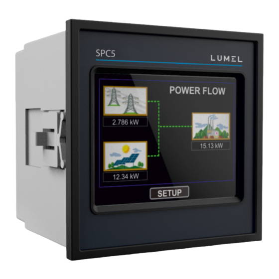
6. Measurement Screens 6.1 Main Screen The Main screen consists of three icons/ buttons : Grid / Generator, Load & Solar touching which takes to the parameters of the corresponding menu. The direction of movement of lines connecting the icons indicate the direction of power flow. -
Page 36: Load Menu
6.3 Load Menu It contains graphical view of power distribution at the load. The contribution of solar & grid (or generator) power is shown in the pie chart along with corresponding percentage. LOAD POWER DISTRIBUTION Load 15.13 kW Solar : 81.5 % 12.34 kW 18.4%... -
Page 37: Indications On Main Screen
SOLAR CAPACITIES (kW) CONNECTION STATUS Inverter Inverter Inv. Panel Inv. Inverter Capacity Type Capacity Status 35.00 RADIUS Active MAIN BACK MAIN BACK Comparison of Inverter Inverter Type (Make) and corresponding connection Capacity and Panel Capacity status for individual inverter. for individual inverter. 6.5 Indications on main screen : Fault :If the meter relay is selected in Automatic mode (Section 3.2.4) and if the fault condition occurs (Section 7) the same is indicated on the main screen. -
Page 38: Relay Tripping Functionality
7. Relay Tripping Functionality : This instrument is provided with 1 relay for disconnecting the inverter(s) from the Grid / Generator if fault condition occurs. The fault condition is different for Grid and Generator. Fault condition when Grid is connected : Consider that the Grid is connected to the Load, i.e., Generator is not sensed at the addon card. - Page 39 Fault condition when Generator is connected : Consider that the Generator is connected to the Load, i.e., Generator is sensed at the addon card. Atleast 1 Inverter Disconnect Generator Power All Inverters Connected time Relay De-Energize Relay Energize (-1) x (Threshold value) ON Delay OFF Delay Figure 7.2: Waveform of Relay functioning for fault condition in Energized Configuration...
- Page 40 Relay functioning for De-Energized configuration : Grid Power All Inverters Connected Atleast 1 Inverter Disconnect time Relay Energize Relay De-Energize OFF Delay ON Delay Figure 7.3: Waveform of Relay functioning for fault condition in De-Energized Configuration Atleast 1 Inverter Disconnect Generator Power All Inverters Connected time...
-
Page 41: Phasor Diagram
8. Phasor Diagram : Capacitive Inductive Capacitive Inductive Sign of Sign of Sign of Inductive / Connections Quadrant Active Reactive Power Capacitive Power ( P ) Power ( Q ) Factor ( PF ) Import Import Export Export Inductive means Current lags Voltage Capacitive means Current leads Voltage When the Instrument displays Active When the Instrument displays Active... -
Page 42: Installation
9. Installation SLIDE IN THIS DIRECTION PANEL AND LOCK Mounting is by four side clamps, slide the side clamps through side slot till side clamp gets firmly locked in a groove (Refer fig.) Consideration should be given to the space required behind the instrument to allow for bends in the connection cables. -
Page 43: Case Dimensions And Panel Cut-Out
Note: It is good practice to install sensitive electronic instruments that are performing critical functions, in EMC enclosures that protect against electrical interference which could cause a disturbance in function. 2. Avoid routing leads alongside cables and products that are, or could be, a source of interference. 3. -
Page 44: Auxiliary Supply
For safety reasons, CT secondary connections should be grounded in accordance with local regulations. 10. Connection Block Diagram Utility Grid/ Generator Mains RS-485 Data To PC, SCADA, SPC5 etc. for data acquisition RS-485 Gensense Relay Inverter Grid/ Generator Voltage No export... -
Page 45: Wiring Diagram
11. Wiring Diagram 3-PHASE 4-WIRE UNBALANCED DIGITAL METERING SYSTEM 13 14 2 5 8 11 1 3 4 6 7 9 SUPPLY... - Page 46 12. Specification System Type 3P4W (Fixed) Inverters Maximum Inverters Compatibility with Radius PVSA 1 min. approx. Correction Time Overall time taken to prevent the reverse power flow considering the inverter response time. Display TFT LCD 3.5" Graphical LCD, resolution 320x240 pixels Update Approx.
- Page 47 Overload withstand Voltage input 2 x Rated Value (1s application at 10s intervals) repeated 10 times Current input 2 x nominal Value (1s application at 5min intervals) repeated 5 times Auxiliary Supply External Higher Aux. 100V to 550V AC/DC External Higher Aux. Nominal Value 230V AC/DC 50/60 Hz for AC Aux Aux Frequency Range 45 to 65 Hz <...
- Page 48 Reference conditions for Accuracy : Reference temperature 23 C + 2 C Input frequency 50 or 60Hz ± 2% Input waveform Sinusoidal (distortion factor 0.005) Auxiliary supply voltage Rated Value + 1 % Rated Value + 1 % Auxiliary supply frequency Voltage Range 50...
- Page 49 Standards EMC Immunity IEC 61326 10V/m min-Level 3 industrial low level electromagnetic radiation environment IEC 61000-4-3. IEC 61010-1 , Year 2001 Safety IP for water & dust IEC 60529 Isolation Dielectric voltage withstand 2.2 kV RMS 50 Hz for 1 minute test between circuits and between all electrical circuits accessible surfaces...
-
Page 50: Connection For Dual Modbus Addon Card
Relay Output Options: Port 1 NO + 1 NC Switching Voltage and Current 250VAC, 5A AC 30VDC, 5A DC Modbus Options: Dual Modbus (RS485 Data & RS485 Inverters) Protocol ModBus ( RS 485 ) Baud Rate 4.8k, 9.6k, 19.2k, 38.4k, 57.6k ( Programmable ) Parity Odd or Even, with 1 stop bit,... - Page 51 The Information contained in these installation instructions is for use only by installers trained to make electrical power installations and is intended to describe the correct method of installation for this product. It is the user's responsibility to determine the suitability of the installation method in the user’s field conditions.
- Page 52 LUMEL S.A. ul. Słubicka 4, 65-127 Zielona Góra, Poland tel.: +48 68 45 75 100, fax +48 68 45 75 508 www.lumel.com.pl Technical support: tel.: (+48 68) 45 75 143, 45 75 141, 45 75 144, 45 75 140 e-mail: export@lumel.com.pl...
Need help?
Do you have a question about the SPC5 and is the answer not in the manual?
Questions and answers