Table of Contents
Advertisement
Quick Links
Advertisement
Table of Contents

Related Manuals for Lumel SMC series


Summary of Contents for Lumel SMC series
- Page 1 PROGRAMMABLE LOGIC CONTROLLER SMC TYPU USER’S MANUAL...
-
Page 3: Table Of Contents
CONTENTS 1. APPLICATION AND DESIGN 2. SET OF THE DELIVERED CONTROLLER 3. BASIC REQUIREMENTS AND SAFETY SERVICE 4. DESCRIPTION OF THE DESIGN AND INSTALLATION 4.1. Design Description 4.2. Terminal Description 4.3. Installing COM Port for Windows 4.4. Installing COM Port Controllers in the Computer 5. -
Page 4: Application And Design
1. APPLICATION AND DESIGN The SMC programmable logic controller is the central decision module in distributed measuring and control systems with a quick MODBUS communication (up to 115.2 kbit/s). It can service remote analogue and logic input/output modules, measuring transducers, inverters, microcontrollers, recorders, display panels, HMI touch screen panels, etc. -
Page 5: Basic Requirements And Safety Service
3. BASIC REQUIREMENTS, SAFETY SERVICE Symbols located in this user’s manual mean: WARNING! Warning of potential, hazardous situations. Especially important. One must acquaint with this before connecting the SMC controller. The non-observance of notices marked by these symbols can occasion the damage of the instrument. CAUTION! Designates a general useful note. -
Page 6: Description Of The Design And Installation
4. DESCRIPTION OF THE DESIGN AND INSTALLATION 4.1. Design Description The SMC controller is destined to be fixed on a 35 mm rail support (acc. to EN 60715) in the way shown on the fig. 2. Fig. 2. Fixing way of the SMC controller... -
Page 7: Terminal Description
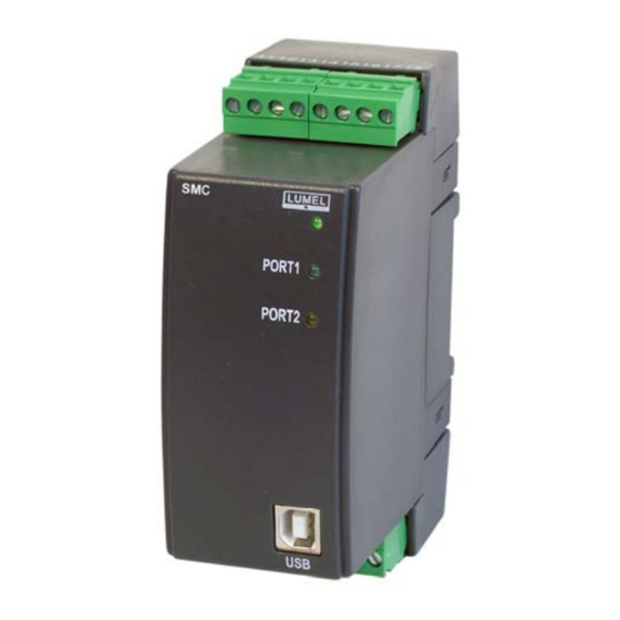
4.2. Terminal Description The supply and external signals must be connected in accordance with the fig. 3. Individual outlets have been described in the table 1. Caution: One must pay a particular attention on the correct connection of external signals (see table 1) There are 3 signalling diodes on the frontal plate D1 Two-colour diodes. -
Page 8: Installing Com Port For Windows
The current program on a CD is included in the controller set. The current programming package for SMC is included on the www.lumel.com.pl/download page. All updatings can be carried out by means of the programming package runs on this page. -
Page 9: Controller Configuration
5. CONTROLLER CONFIGURATION NOTE : The language description and examples of controller programming are included in the programming manual. Before proceeding to the controller configuration, one must prepare the controlling program taking advantage of tools included in the controller set. 5.1. - Page 10 b) Tools > Configurer Fig. 5. Starting the configurer as tools ) Menu start: CPDeV > CPCon Fig. 6 Starting the configurer from the system menu The first way is applied directly after the Project compilation. The two next require the file import from the compiled project.
- Page 11 5.1.4 Menu CPCon Fig. 8. File menu of the CPCon program Fig. 9. Transmission menu of the CPCon program Buttons under the table (Fig. 7) realizes a part of functions given in options. The project file import is necessary, when CPCon was started in the second or third way. The read out metric contains documentation data of the carried out program by the controller.
-
Page 12: Smc Communication <-> Devices (Sm Modules)
• Horizontal communication Communication parameters SMC ↔ in/out modules can be selected from the tag (or other devices). Parameters must be the same as they set in modules. The 8N1 mode selected below means 8-bit data, odd parity (N) and 1 stop bit. Fig. - Page 13 • Press the button in the program window. The creator information window appears Fig. 13. Creator of communication tasks 5.2.1 Device Number. MODBUS Function • Input devices (e.g. SM5) can be read out by groups by means of the function with Code 3 (readout of registers , named FC3 here (Function Code 3).
- Page 14 Among global variables of our project, we highlight input variables. The logic addresses of variables are e.g. 0,1, 2, and the dimension of each is a byte. Addresses of input variables are successive numbers, then the readout by groups (by blocks) is suitable. Note.
- Page 15 5.2.5. Control Variables The last creator window serves for the configuration of transmission control, if the appropriate fragment of the program forecasts it. It is indicated in the window, to which of variables has to be write the information about the correctness or incorrectness of the communication, which of the variable is destined to write the communication time in, and by means of which, one can enable or disable communication tasks.
- Page 16 5.2.7. Direct Filling of the Table (alternative for the Creator). Addition and elimination of the row – right Mouse key Function code, kind of conversion, priority – selection from the menu. Other cells – written in the ordinary way. 5.2.8. Writing the Configuration into the File. The table of communication tasks can be utilized in later modifications or in other Projects.
-
Page 17: Writing The Program In Smc
5.2.9. Configuration Readout ( for Check, Modification, ETC.) • Press the button Select the file in the appearing window Open file with the confirmation of the communication subsystem and click Open. Fig. 21 Reading in the project to the file In case of the file Start_Stop.xmc, the table of communication tasks will be looked like previously. -
Page 18: Description Of The Transmission Protocol Functions
DESCRIPTION OF THE TRANSMISSION PROTOCOL FUNCTIONS Following functions of the MODBUS protocol were implemented in the controller. code Meaning Readout of n-registers Write of a single register Write of n-registers Identification of the slave device 6.1. Readout of n-registers (code 03) Request: The function enables the readout of values included in register, in the addressed slave device. -
Page 19: Writing In N-Registers (Code 16)
6.3. Writing in n-registers (Code 16) Request: The function is available In the broadcast mode. It enables the modification of the register contents. Example: Write of two registers beginning from the register with the address 136. address funct. regist. regist. numb. -
Page 20: Technical Data
Data Field: In the correct response, the slave device can return data on the data field (some information requested by the master unit). In the erroneous response, the slave device returns the terror code on the data field. It defines the slave device conditions, which causes the error. - Page 21 Rated operating conditions: - supply voltage 20…24…40 V a.c./d.c. or 85…230…253 V a.c./d.c. - supply voltage frequency 40…50/60…440 Hz - ambient temperature 0…23…55ºC - relative air humidity < 95% (inadmissible condensation of water vapor) - external magnetic field < 400 A/m - working position Storage and transport conditions: - ambient temperature...
-
Page 22: Ordering Codes
9. ORDERING CODES SMC- PROGRAMMABLE CONTROLLER 85…253 V a.c/d.c. Supply voltage: 20…40 V a.c/d.c. standard Version: non-standard settings custom-made* Polish Language: English other without extra l requirements Acceptance tests: with an extra quality inspection certificate acc. to customer’s request * * After agreeing with the manufacturer ORDERING EXAMPLE The code: SMC-1- 00- E-1 means:... -
Page 23: Maintenance And Guarantee
10. MAINTENANCE AND GUARANTEE The applied battery in the SMC controller requires replacement every 5 years. In order to replace the battery, one must send the controller to the Manufacturer’s Service Department. In case of some incorrect operations: 1. In the period given in the annexed guarantee card One should take the controller down from the installation and return it to the Manufacturer’s Quality Control Dept. - Page 24 All our instruments have CE mark . SMC-09/1 January 2010 For more information, please write to or phone our Export Department Lubuskie Zakłady Aparatów Elektrycznych - LUMEL S.A. ul. Sulechowska 1 65-022 Zielona Góra – Poland Export Department: Tel.: (48-68) 32 95 1 00 (exchange) Tel.: (48-68) 329 53 02...
Need help?
Do you have a question about the SMC series and is the answer not in the manual?
Questions and answers