Miele ProLine CS 1221-1 Operating And Installation Instructions
Hide thumbs
Also See for ProLine CS 1221-1:
- Operating and installation instructions (64 pages) ,
- Operating and installation instructions (60 pages) ,
- Operating and installation instructions (60 pages)
Table of Contents

Related Manuals for Miele ProLine CS 1221-1


Summary of Contents for Miele ProLine CS 1221-1
- Page 1 Operating and installation instructions ProLine induction cooktop To prevent the risk of accidents or damage to the appliance, it is essential to read these instructions before it is installed and used for the first time. en-AU, NZ M.-Nr. 09 199 860...
-
Page 2: Table Of Contents
Contents Warning and Safety instructions................ 4 Caring for the environment ................ 15 Overview....................... 16 Cooktop......................... 16 CS 1212-1 ...................... 16 CS 1221-1 ...................... 17 CS 1222...................... 18 Indicators....................... 18 Control knob symbols ................... 19 Display........................19 Cooking zone data ....................20 Before using for the first time ................ - Page 3 Contents Problem solving guide .................. 37 Optional accessories .................. 39 Safety instructions for installation.............. 40 Safety distances .................... 41 Installation notes .................... 43 Building-in dimensions .................. 44 CS 1212-1 ......................44 CS 1221-1 / CS 1222 .................... 45 Installing several ProLine elements.............. 46 Installation......................
-
Page 4: Warning And Safety Instructions
They contain important notes on installation, safety, use and maintenance. Miele cannot be held liable for damage caused by non-compliance with these Warning and Safety instructions. Keep these instructions in a safe place and ensure that new users... - Page 5 This cooktop is not suitable for outdoor use. It is intended only to cook food and keep it warm. Any other use is not supported by Miele and could be dangerous. This cooktop is not intended for use by people (including children)
- Page 6 Warning and Safety instructions Safety with children Young children must not be allowed to use this appliance. Older children may only use the appliance if its operation has been clearly explained to them and they are able to use it safely. They must be aware of the potential dangers caused by incorrect operation.
- Page 7 Unauthorised installation, maintenance and repairs can cause considerable danger for the user. Installation, maintenance and repairs must only be carried out by a Miele authorised technician. Damage to the cooktop can compromise your safety. Check the appliance for visible signs of damage. Do not use the cooktop if it is damaged.
- Page 8 The manufacturer's warranty will be invalidated if the appliance is not repaired by a Miele authorised service technician. Faulty components must only be replaced by genuine Miele spare parts. The manufacturer can only guarantee the safety of the appliance when Miele replacement parts are used.
- Page 9 Warning and Safety instructions If the cooktop is installed behind a furniture door, do not close the door while the cooktop is in operation. Heat and moisture can build up behind the closed door. This can result in damage to the cooktop, the housing unit and the floor.
- Page 10 Warning and Safety instructions Correct use The cooktop gets hot when in use and remains hot for a while after being switched off. There is a danger of burning until the residual heat indicators go out. Oil and fat can overheat and catch fire. Do not leave the cooktop unattended when cooking with oil and fat.
- Page 11 Warning and Safety instructions You could burn yourself on the hot cooktop. Protect your hands with heat-resistant pot holders or gloves when handling hot pots and pans. Do not let them get wet or damp, as this causes heat to transfer through the material more quickly with the risk of scalding or burning yourself.
- Page 12 Warning and Safety instructions Because induction heating works extremely quickly, the base of the pan could heat up to the temperature at which oil or fat self- ignites within a very short time. Do not leave the cooktop unattended whilst it is being used.
- Page 13 Warning and Safety instructions Where several ProLine elements are installed side by side: Hot objects can damage the seal of the cover strip. Do not place hot pans near or on the cover strip. The cooking process has to be supervised. A short term cooking process has to be supervised continuously.
- Page 14 Warning and Safety instructions Cleaning and care Do not use a steam cleaning appliance to clean this appliance. The steam could reach the electrical components and cause a short circuit. If the cooktop is built in over a pyrolytic oven, the cooktop should not be used whilst the pyrolytic process is being carried out, as this could trigger the overheating protection mechanism on the cooktop (see relevant section).
-
Page 15: Caring For The Environment
Caring for the environment Disposal of the packing Disposing of your old material appliance The transport and protective packaging Electrical and electronic appliances has been selected from materials which often contain valuable materials. They are environmentally friendly for also contain specific materials, disposal, and can normally be recycled. -
Page 16: Overview
Overview Cooktop CS 1212-1 a Cooking zone with TwinBooster b Cooking zone with Booster c Cooking zone display d Cooking zone allocation symbol e Indicators f Control knob for the rear cooking zone g Control knob for the front cooking zone... -
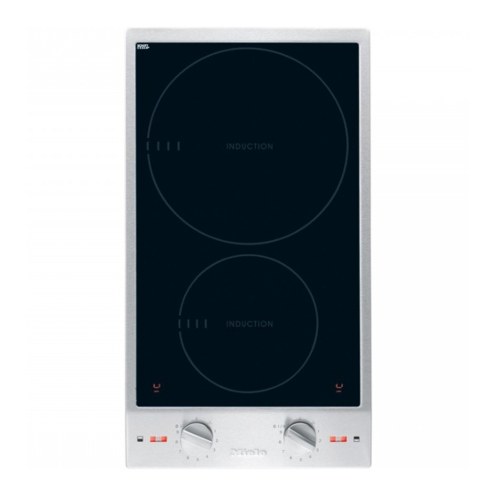
Page 17: Cs 1221-1
Overview CS 1221-1 a Cooking zone with TwinBooster b Cooking zone display c Indicators d Control knob for the cooking zone... -
Page 18: Indicators
Overview CS 1222 a Extended zone with TwinBooster b Cooking zone with Booster c Cooking zone display d Cooking zone allocation symbol e Indicators g Control knob for the front cooking zone h Control knob for the rear cooking zone Indicators ... -
Page 19: Control Knob Symbols
Overview Control knob symbols Symbol Description Cooking zone off Keeping warm function 1 – 9 Power settings Booster level 1 B I/II TwinBooster with 2 levels Display Symbol Description No pan on cooking zone or pan unsuitable (see “Induction - How it works”) ... -
Page 20: Cooking Zone Data
Overview Cooking zone data Cooking zone CS 1212-1 Ø in cm* Rating in watts for 230 V** 10–16 Normal 1400 Booster 2200 16–23 Normal 2300 TwinBooster, level 1 3000 TwinBooster, level 2 3700 Total 3700 * Cookware of any diameter may be used within the specified range. ** The wattage quoted may vary depending on the size and material of the pans used. -
Page 21: Before Using For The First Time
Before using for the first time Please stick the extra data plate for Switching on the cooktop for the appliance supplied with this the first time documentation in the space provided in the “Service” section of this When the cooktop is first switched on booklet. -
Page 22: Induction
Induction How it works Risk of burning due to hot items! When the cooktop is switched on, An induction coil is located under each either deliberately or by mistake, or cooking zone. When a cooking zone is when there is residual heat present, switched on, this coil creates a there is a risk of metal items placed magnetic field which impacts directly... -
Page 23: Noises
Induction Noises When using an induction cooking zone, the following noises can occur in the pan, depending on what it is made of and how it has been constructed. On the higher power settings, the appliance might buzz. This will decrease or cease altogether when the power setting is reduced. -
Page 24: Suitable Cookware
Induction – Please note that the maximum Suitable cookware diameter quoted by manufacturers Suitable pans include: often refers to the diameter of the top rim of the pot or pan. The diameter of – stainless steel pans with a base that the base (generally smaller) is more can be magnetised important. -
Page 25: Tips On Saving Energy
Tips on saving energy – Use a lid whenever possible to minimise heat loss. – Select a smaller pan when cooking small quantities. A smaller pan uses less energy than a larger pan with very little in it. – Cook with as little water as possible. –... -
Page 26: Power Level Range
Power level range Settings Keeping warm Melting butter Dissolving gelatine Melting chocolate Making milk puddings Warming small quantities of liquid Cooking rice Defrosting frozen vegetables (blocks) Making porridge Warming liquid and semi-solid foods Making omelettes or lightly fried eggs Steaming fruit Cooking pasta/dumplings Steaming vegetables and fish... -
Page 27: Operation
Operation Control knobs Switching off Turn the control knob anti-clockwise The control knobs must not be turned to the 0 position past the B I or the B I/ to the 0 position. II positions. After all cooking zones are switched Switching on off, the in-operation indicator goes out. -
Page 28: Auto Heat-Up
Operation Auto heat-up Continued Heat-up time cooking setting [min:sec] When Auto heat-up has been activated, the cooking zone switches on approx. 0:15 automatically at the highest setting and approx. 0:15 then switches down to the continued cooking setting you have previously approx. -
Page 29: Booster
Operation In each case two cooking zones are Booster linked together in order to provide The cooking zones are equipped with a sufficient power for the Booster. one-level Booster or two-level While the Booster is in operation some TwinBooster (see “Overview - of the power is taken away from the Cooktop”). - Page 30 Operation Switching on the Booster Switching off the Booster / TwinBooster Turn the control knob clockwise past Set a different power setting. the 9 position to B I and then back to the 9 position. The booster symbol and B will go out. ...
-
Page 31: Keeping Warm
Operation Setting the keeping warm function Keeping warm Turn the control knob clockwise to The keeping warm function is for position . keeping food warm that has just been cooked, i.e. food that is still hot. It is not for reheating food that has gone cold. -
Page 32: Safety Features
Safety features System lock Safety switch-off The safety switch-off mechanism is The system lock can only be activated triggered automatically if one of the if all the cooking zones are switched cooking zones is heated for an off. unusually long period of time. This period of time depends on the power Your cooktop is equipped with a system lock to prevent the cooking zones being... -
Page 33: Overheating Protection
– The cooking zone switches off If, despite removing the cause, the automatically. appears in the overheating protection mechanism cooking zone display. triggers again, contact Miele. – Other cooking zones switch off automatically. Switch off the affected cooking zone(s). -
Page 34: Cleaning And Care
Cleaning and care Allow the ProLine element to cool Risk of burning on hot cooking down before cleaning. zones! The cooking zones will be hot after Clean the ProLine element and use. accessories after each use. Switch the cooktop off. ... -
Page 35: Ceramic Surface
(spots with a The seal between the ceramic metallic appearance) can be removed surface and the frame could be using the Miele ceramic and stainless damaged. steel cooktop cleaner. Do not use pointed objects for ... -
Page 36: Stainless Steel Frame/Control Panel
Cleaning and care Stainless steel frame/control panel Clean the frame and the control panel with a solution of warm water and a little washing-up liquid applied with a soft sponge. You can also use a ceramic and stainless steel cleaning agent. We recommend using a stainless steel conditioning agent to help prevent resoiling (see “Optional accessories”). -
Page 37: Problem Solving Guide
Miele. This will save you time and money because you will not need a service call. If, after reading this guide, you cannot remedy the problem yourself, please call Miele (see back cover for details). - Page 38 Problem solving guide Problem Possible cause and remedy The symbol flashes in There is no pan on the cooking zone, or the pan is unsuitable. a cooking zone display. Use suitable pans (see “Induction - Suitable cookware”). In the display for a The power setting was reduced because the booster cooking zone ...
-
Page 39: Optional Accessories
These products can be ordered from the Miele online shop. They can also be ordered directly from Removes heavy soiling, limescale Miele (see end of this booklet for deposits and aluminium residues. contact details). Original Miele all purpose microfibre cloth... -
Page 40: Safety Instructions For Installation
Safety instructions for installation Risk of damage from incorrect installation. Incorrect installation can cause damage to the ProLine appliance. The ProLine appliance must only be installed by a qualified and competent person in strict accordance with current national and local safety regulations. ... -
Page 41: Safety Distances
Safety distances Safety distance above the ProLine appliance A minimum safety distance must be maintained between the ProLine appliance and the rangehood above it. See the rangehood manufacturer's operating and installation instructions for details. If the rangehood manufacturer's instructions are not available or if flammable objects are installed above the ProLine appliance (e.g. - Page 42 Minimum horizontal distance from the the shelf to accommodate the cable. right or left edge of the ProLine Miele recommends a gap at the front of element to a combustible surface: the shelf of 20 mm to ensure good 40 mm CS 1212-1, CS 1221-1, ventilation.
-
Page 43: Installation Notes
Installation notes Sealing between the ProLine Tiled worktop element and the worktop Grout lines and the hatched area underneath the ProLine element frame must be smooth and even. If they are The ProLine element and the not, the ProLine element will not sit worktop may be damaged if the flush with the worktop and the sealing appliance needs to be removed after... -
Page 44: Building-In Dimensions
Building-in dimensions CS 1212-1 a Spring clamps b Front c Installation height d Mains connection box with mains connection cable, L = 2000 mm... - Page 45 Building-in dimensions CS 1221-1 / CS 1222 a Spring clamps b Front c Installation height d Mains connection box with mains connection cable, L = 2000 mm...
-
Page 46: Installing Several Proline Elements
Installing several ProLine elements Example: 3 ProLine elements a Spring clamps b Spacer bars c Gap between spacer bar and worktop d Cover strips e ProLine element width less 8 mm f ProLine element width g ProLine element width less 8 mm h Worktop cut-out... - Page 47 Installing several ProLine elements Calculating the worktop cut-out The frames of the ProLine elements overlap the worktop at the outside right and left by 8 mm on each side. Add up the widths of the ProLine elements and subtract 16 mm from this sum. Example: 288 mm + 288 mm + 380 mm = 956 mm - 16 mm = 940 mm The ProLine elements are 288 mm, 380 mm or 576 mm wide depending on...
-
Page 48: Installation
Installation Preparing the worktop Make the worktop cut-out as shown in “Building-in dimensions” or as calculated (see “Installing several ProLine elements”). Remember to maintain the minimum safety distances (see “Safety distances”). Wooden worktops Seal the cut surfaces of wooden worktops with a suitable heat- resistant sealant to avoid swelling caused by moisture. - Page 49 Installation Granite and marble worktops You will need heavy-duty double- sided tape (not supplied) to secure the spring clamps and spacer bars. Apply silicone adhesive to the side edges and bottom edge of the spring clamps and spacer bars . ...
- Page 50 Installation Fitting several ProLine elements Installation with a downdraft extractor Push the built-in ProLine element to the side until the holes in the spacer Please refer to the separate “Downdraft bar can be seen. extractor with ProLine appliances” instruction manual for details about installing a downdraft extractor with a ProLine appliance.
- Page 51 Installation Connecting the ProLine appliance Connect the ProLine element/ elements to the electricity supply and, if applicable, to the gas supply (see “Electrical connection” and “Gas connection”). Check that each ProLine element is working. Removing a ProLine appliance If the ProLine element is not accessible from below, take hold of it with both hands at the back, pull it...
-
Page 52: Electrical Connection
Risk of damage from incorrect by a suitably qualified and competent connection. person in strict accordance with current Danger of injury! Miele cannot be local and national safety regulations. held liable for unauthorised Connection of the ProLine appliance to installation, maintenance and repair... - Page 53 Electrical connection Total power output See data plate. Connection AC 230 V, 50 Hz The voltage and rated load are given on the data plate. Please ensure these match the household mains supply. Residual current device For extra safety, it is advisable to protect the ProLine appliance with a suitable residual current device (RCD) with a trip range of 30 mA.
- Page 54 If the mains cable needs to be replaced, it must be replaced with a special connection cable, type H 05 VV-F (PVC insulated), available from Miele, by a Miele authorised service technician or suitably qualified and competent electrician in order to avoid a hazard.
-
Page 55: Service
Service Contact in case of fault In the event of any faults which you cannot remedy yourself, please contact Miele. Contact information for Miele can be found at the end of this booklet. Please quote the model and serial number of your appliance when contacting Miele. - Page 59 Miele Experience Centre South Melbourne: Freemans Bay, Auckland 1011 206-210 Coventry Street South Melbourne, VIC 3205 Miele Experience Centre Auckland: Miele Experience Centre and Office Sydney: 8 College Hill 3 Skyline Place Freemans Bay, Auckland 1011 Frenchs Forest, NSW 2086 Telephone:...
- Page 60 CS 1212-1, CS 1221-1, CS 1222 en-AU, NZ M.-Nr. 09 199 860 / 06...
Need help?
Do you have a question about the ProLine CS 1221-1 and is the answer not in the manual?
Questions and answers