
Summary of Contents for WACON AquaInform Sycon 2500
- Page 1 on-line water hardness monitor DocomentCode:: Wacon_Sycon 2500_oprerational manual_2010-10-01_GB...
- Page 3 NTRRODUCTION NTRODUCTION We appreciate your purchase of the on-line water hardness Limit Analyser based on Sycon 2500 series. The on-line water hardness Limit Analyser is part of a water treatment plant. Distribution of this manual is intended for the manufacturer and the owner of this plant.
- Page 4 IMIT NALYSER LINE ATER ARDNESS NALYSER ABLE OF ONTENTS 2500 S UMMARY YCON ERIES HAPTER AFETY WARNINGS RECAUTIONS YMBOLS USED HAPTER PECIFICATION AND VERVIEW PECIFICATION AND INTENDED USE → G ENERAL PECIFICATION → P HYSICAL DATA → M ONITORING CAPABILITIES →...
- Page 5 IMIT NALYSER LINE ATER ARDNESS NALYSER HAPTER AINTENANCE AND SERVICE → C HANGING ERISTALTIC NDICATOR → C LEANING OF IXING HAMBER → C HANGING OF PARE ARTS → C HANGING OF NDICATOR OTTLE → C HANGING OF EPLACEMENT ARTS HAPTER IAGNOSTIC UNCTION →...
- Page 6 ATER ARDNESS NALYSER With limit Analyser, WACON offers a very compact and easily operated water analyser for automatic on-line detection of hardness leakages and quality control of water softeners. The system controls selectable limit values according to the colorimetric principle. A broad range of functions (incl. BOB) guarantee reliable field-operation.
-
Page 7: Safty Instructions
HAPTER AFTY NSTRUCTIONS IMIT NALYSER HAPTER AFETY WARNINGS RECAUTIONS This Chapter explains the danger and precautionary signs and notes that apply to the handling, installation, wiring and maintenance of the S 2500 series YCON Limit Analyser. This manual describes the installation and operation of the on-line water- hardness analyser of type Limit Analyser H based on S 2500 series. - Page 8 AFTY NSTRUCTIONS HAPTER IMIT NALYSER Safty instructions and symbols used In this manual you will find specific safety instructions to indicate the unavoidable residual risks when operating the unit. These residual risks imply dangers to ● People ● Product / Plant / Machinery ●...
- Page 9 HAPTER AFTY NSTRUCTIONS IMIT NALYSER Work on hydraulic and pneumatic equipment ● Maintenance and repair of hydraulic and pneumatic equipment shall be carried out by specially trained personnel ! ● Before all maintenance and repair work, the pneumatic and hydraulic equipment of the system / machine must be depressurised ! ●...
-
Page 10: Scope Of Delivery
AFTY NSTRUCTIONS HAPTER IMIT NALYSER Storage We recommend storing equipment not longer than a year, because you lose the warranty. Store equipment under following conditions. ● Cool and dry location / ambient temperature between -5 and 45 °C NOTE Scope of Delivery Scope includes the following modules: ●... -
Page 11: Chapter 2 Specification
HAPTER PECIFICATION IMIT NALYSER HAPTER PECIFICATION The Limit Analyser is used for the automatic monitoring of hardness in water. We recommend that the user read this chapter before installation of the device for safety operation. General specification 85 … 264 V AC 47… 63Hz Power-supply Power consumption 25 VA (on operation) - Page 12 32-089 100 Cleaning solution for acryl glass mixing chambers → 1000 ml cleaning solution FIT 3000 → sample cooler PC 200 order no. 30-015 100 PC 400 order no. 32-015 200 For details please refer to our home page www.wacon.eu...
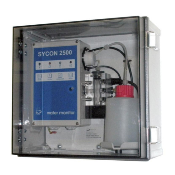
- Page 13 HAPTER PECIFICATION IMIT NALYSER 2.2 Overview – limit analyser – configuration . 2.1 OSING ONTROL OSING ATER UTLET PTICAL ATH WITH IGHT OURCE AND IXING RECEIVER HAMBER ATER NLET OLINOID ALVE EHIND OTTLE AGNETIC TIRRER NDICATOR OTTLE IRECTION OF AMPLE ATER NLET RESSURE OF...
-
Page 14: Led Display
PECIFICATION HAPTER IMIT NALYSER – D . 2.2 2.3 L IMIT NALYSER ISPLAY ONFIGURATION LED D ISPLAY VALUATION RESULT REEN ONDITION OWER ONDITION ELLOW NALYSIS ACTIV ACK OF NDICATOR LARM ONTROL UTTONS START STARTING ANALYSIS MANUALLY FLUSH RINSING MIXING CHAMBER MANUALLY INDICATOR DOSING INDICATOR... - Page 15 HAPTER PECIFICATION IMIT NALYSER LIST LLUSTRATION order no. description 33-090 002 magnetic stirrer 3 3 -0 9 0 0 3 8 3 3 -0 9 0 0 0 8 33-090 007 O-Ring 17x2 33-090 008 bottle connection 33-090 010 bottle cap 3 3 -0 9 0 7 1 6 33-090 011 suction lance...
- Page 16 PECIFICATION HAPTER IMIT NALYSER 2-5 Operation principle of Sycon 2500 A monitoring cycle of Sycon 2500 follows 5 steps The solenoid valve opens, washing and rinsing the mixing chamber with sample water. Old sample water Washing and rinsing mixing chamber with remaining in the container is pushed out, and the sample water.
- Page 17 (Note that more frequent replacement may be necessary, depending on the application.) [11] Compact in design, easy to install The main unit is installed easily on a wall. (→ page 19) Installation is a simple process Wacon provides the most compact designed devices of this type.
- Page 18 PECIFICATION HAPTER IMIT NALYSER [12] Remote signal input function Connection the remote non-voltage signal for example from a flow- or level-control-device or from regenerating water softener prevents a false detection that can occur, for instance, while the water softener is regenerating or no water flows, thus providing more accurate evaluation (→...
-
Page 19: Installation Requirements
HAPTER NSTALLATION AND OMMISSIONING IMIT NALYSER HAPTER NSTALLATION AND OMMISSIONING IMIT NALYSER 3.1 Installation Requirements The analyser shall be used only to determine a parameter in the process water. A proper operation can only be guaranteed by use of indicators which were (→... - Page 20 NSTALLATION AND OMMISIONING HAPTER IMIT NALYSER 3.3 Installation in 4 steps The analyser can be mounted with or without protective housing. The manufacturer offers a standard housing; the mounting and dimensions are described in this guide: Custom-built or tailor made enclosures for the devices of the series aqua inform LimitAnalyser / aqua inform TrendAnalyser / SYCON 2500 / SYCON 2800 and SYCON 3000 as well as devices with custom names and labels that are technically based on these ranges are not described in detail in this manual.
-
Page 21: Installation And Commissioning
HAPTER NSTALLATION AND OMMISSIONING IMIT NALYSER Fig. 3.1 terminal layout and internal connections li g h t e m it t i n g d io d e in d ic a t o r s a m p le m a in s a d a p t e r p u m p in p u t v a lv e... - Page 22 NSTALLATION AND OMMISIONING HAPTER IMIT NALYSER Fig 3.2 connection instructions m a in s a d a p t e r p ic tu r e d p o si ti o n o f REL1 a n d REL2 : ST 3 d e v ic e c u r re n tle s s - r e la y d ro p e d o u t w a r n in g...
- Page 23 Safety data sheets on common types of indicators are available for download WARNING on our website www.wacon.eu We accept no liability for permanent stains by the dyes in the indicator and personal damage caused by improper handling of the indicator.
- Page 24 NSTALLATION AND OMMISIONING HAPTER IMIT NALYSER Fig. 3.3 wall mounting without enclosure 2 0 0 d = 4 2 7 6 x 2 7 6 NLET RESSURE OF AMPLE ATER IRECTION OF . 0.5 … 5.0 1 0 0 ATER AMPLE 1..2 BAR RECOMM...
- Page 25 HAPTER NSTALLATION AND OMMISSIONING IMIT NALYSER connection of relay outputs → relay REL2 limit exceed terminal 7 / 8 / 9 Signal devices and valves can be switched on when the limit is exceeded. The relay switches as → permanent contact or alternatively as → impuls contact to trigger a control system for the regeneration of a water treatment plant.
- Page 26 NSTALLATION AND OMMISIONING HAPTER IMIT NALYSER connection of remote signals → IN digital input terminal 13 / 14 Monitoring while the water softener is in regeneration may erroneously indicate hardness leakage. An attempt to monitor with the water feed stopped would return either hardness leakage in stagnant water in the plumbing or a system error due to a lack of flow.
-
Page 27: Operating The System
HAPTER PERATING THE YSTEM IMIT NALYSER HAPTER PERATION OF IMIT NALYSER 4.1 Summary of limit analyser of Sycon 2500 series Analysers of Sycon 2500 series in model H are designed to monitor a certain limit-value-concentration of total or carbonate hardness in water through the use of colormetry analysis. -
Page 28: Before First Use
PERATING THE YSTEM HAPTER IMIT NALYSER 4.2 Before first use → Make sure that the steps from chapter 3 (→ page 19 ff) have been performed properly. → Make sure that the unit is securely mounted to a wall or suitable suspension. - Page 29 HAPTER PERATING THE YSTEM IMIT NALYSER 4.3 Setting the program switches The Limit Analyser is programmed using small dual-in-line-switch S1-S10 and adjusted to specific operating requirements. switch off the unit and open the lid of he controller → WARNING supply voltage 85 … 264 V AC 47 … 63Hz →...
- Page 30 PERATING THE YSTEM HAPTER IMIT NALYSER ► setting of flushing time The flushing time before an analysis is set using the potentiometer (left of the DIP switches) in 30 seconds (left) and 10 minutes (right). S P Ü L Z E IT 0 ,5 M in . S P Ü...
- Page 31 HAPTER PERATING THE YSTEM IMIT NALYSER ► analysis interval There are four fixed interval times selectable by varying the position of switch S1 and S2. The choice of analysis interval determines the frequency at which analyses are carried out. The interval time is the time interval between two measurements. If the potential-free input "flow switch"...
- Page 32 PERATING THE YSTEM HAPTER IMIT NALYSER ► function relay REL 1 The relay REL 1 indicates violation of the limit. You can choose between an impulse contact of 3 and 60 seconds for the control of a controller or a permanent contact. For a permanent contact there are two alternatives: 1.
- Page 33 HAPTER PERATING THE YSTEM IMIT NALYSER Start up in 5 steps Make sure that the analyser was installed in accordance with chapter 3 (→ page 19) and the program switches were set properly according to the application like described under Section 4.3 (→ page 29). HINWEIS step 1 switch on the unit...
- Page 34 PERATING THE YSTEM HAPTER IMIT NALYSER → display of functions operating of the device Make sure that the analyser was installed in accordance with chapter 3 (→ page 19) and the program switches were set properly according to the application described under Section 4.3 (→ page 29). →...
- Page 35 HAPTER PERATING THE YSTEM IMIT NALYSER lack of indicator blue: blue LED-display lights continuously, thus indicating that the indicator stocks is less than about 30% blue-flashing: the display will flash, signaling that the stock of indicator is less than 10%. At the same time, the fault relay REL2 enabled.
- Page 36 PERATING THE YSTEM HAPTER IMIT NALYSER 2b. blue-flashing + red blue lack indicator (blue-flashing) + alarm message (red): The red LED-display lights permanent and signals in conjunction with the flashing blue LED display “lack of indicator” <10%. → the fault relay was deleted alarm message 3a.
- Page 37 HAPTER PERATING THE YSTEM IMIT NALYSER → control by hand operating the unit Make sure that the analyser was installed in accordance with chapter 3 (→ page 19) and the program switches were set properly according to the application described under Section 4.3 (→ page 29). →...
-
Page 38: Chapter 5 Maintenance And Service
HAPTER PERATING THE YSTEM IMIT NALYSER HAPTER AINTENANCE AND ERVICE To ensure long-term function of the analyser it is necessary to clean the measuring chamber and replace worn parts from time to time depending on the frequency of analysis and general pollution levels. Depending on the load of the appliance maintenance work should be done at intervals of about 6 months. - Page 39 HAPTER AINTAINANCE 2500 YCON ► Maintenance in 3 steps step 1 - step 2A without 2B - step 3 routine maintenance in intervals of app. 4-6 month requirements time app. 30 minutes indicator → page 12 material depending on limit maintenance set no.1 Art.nr.
- Page 40 AINTENANCE HAPTER 2500 YCON AINTENANCE LEANING OF EASURING HAMBER REMOVE CLEANING AND REINSTALL → 2B see page 42 1. First release pressure from water supply line → shut off water supply in water treatment plant → switch on the unit for a while WARNING →...
- Page 41 HAPTER AINTAINANCE 2500 YCON AINTENANCE EFILL NDICATOR AND ESET THE TORAGE OUNTER 1. remove empty indicator bottle → open bottle cap by turning → remove the suction pipe carefully → If indicator fluid leaks, wipe up with a paper towel →...
- Page 42 AINTENANCE HAPTER 2500 YCON step 1 – step 2A – step 2B - step 3 annual maintenance in intervals of 6-12 month requirements time app. 30 minutes indicator → page 27 material : depending on limit maintenance set no.2 Art.nr. 33-090 028 cleaning set Art.nr.
-
Page 43: Replacing Components
HAPTER AINTAINANCE 2500 YCON ► Replacing components Please read the notes at the beginning of Chapter 5 →page 38. → Please read the notes in the data sheets of components WARNING order no. 33-090 014 HANGE OF NLET OLENOID ALVE 1. - Page 44 HAPTER YSTEM HECK IAGNOSTIC UNCTION IMIT NALYSER HAPTER IAGNOSTIC UNCTION To control the device functions, a test program can be turned on. It is necessary to open the cover of the control (→ page 29) and to change the position of DIP-switch combination S9-S10: test program function analysis operation...
- Page 45 – D HAPTER YSTEM HECK IAGNOSTIC UNCTIONS IMIT NALYSER Diagnosis in 13 steps After turning the switch S10 in position ON the test steps described below are called by repeatedly pressing the START button START LED D IAGNOSIS HECK ISPLAY After 1 pressing the START button, the LED lights are reviewed.
- Page 46 – D YSTEM HECK IAGNOSTIC UNKTIONS HAPTER IMIT NALYSER DIP-S IAGNOSIS HECK THE WITCHES After 3 pressing the START button, the DIP-switches are reviewed Each slide switch S1 to S9 is a combination 3. X of LED lights assigned START S1 = GREEN S2 =...
- Page 47 – D HAPTER YSTEM HECK IAGNOSTIC UNCTIONS IMIT NALYSER REL 1 IAGNOSIS HECK ELAY UTPUT After 5 pressing the START button, the relay output REL 1 is reviewed. 5. X START → terminals 7 / 8 / 9 → The red LED will flash and the relay REL1 every second will switched on and off REL 2...
- Page 48 – D YSTEM HECK IAGNOSTIC UNKTIONS HAPTER IMIT NALYSER IAGNOSIS HECK GITATOR After 10 pressing the START button, the function of the agitator is reviewed. 10. X START → The red + blue LED will flash and the agitator will switched on IAGNOSIS HECK IGITAL...
- Page 49 – D HAPTER YSTEM HECK IAGNOSTIC UNCTIONS IMIT NALYSER IAGNOSIS HECK OLOUR ETECTION After 13 pressing the START button, the function of colour detection in the 13. X START optical path of the mixing chamber is reviewed → all four LEDs from green + yellow + blue + red light up The LED „analysis result“...
- Page 50 Notes conversion of he units of the residual/total water hardness °dH °e °fH mval/l mmol/l German degree 1 °dH = 1,253 1,78 17,8 0,357 0,1783 English degree 1 °e = 0,798 1,43 14,3 0,285 0,142 Franch degree 1 °fH = 0,56 0,702 ppm CaCO...
- Page 52 WACON GmbH D-31137 Hildesheim Eduard-Ahlborn-Str. 1 Germany Tel. +49 (0) 5121 28 126 50 Fax. +49 (0) 5121 28 126 99 2010 IN OUR CONTINUING EFFORT TO IMPROVE OUR info@wacon.eu PRODUCT, INFORMATION IN THIS MANUAL MAY www.wacon.eu BE CHANGED WITHOUT PRIOR NOTICE...
Need help?
Do you have a question about the AquaInform Sycon 2500 and is the answer not in the manual?
Questions and answers