EKOM DK50-10 Series User Manual
Hide thumbs
Also See for DK50-10 Series:
- User manual (276 pages) ,
- Installation, operation and maintenance manual (136 pages) ,
- Service manual (20 pages)
Table of Contents
Advertisement
Available languages
Available languages
Quick Links
Advertisement
Chapters
Table of Contents

Related Manuals for EKOM DK50-10 Series


Summary of Contents for EKOM DK50-10 Series
- Page 2 CONTE ENTS CONTE ENTS GENER RAL INFOR RMATION ......................... 6 1. CONFOR RMITY WITH H THE REQ QUIREMEN TS OF THE E EUROPEA AN UNION ....6 2. SYMBOLS S ...........
- Page 3 GENERA AL INFORM MATION ENERAL IN NFORMATIO ead the Use er manual c carefully an d keep it be efore use o of the produ uct. The Use er manual p provides formation on n correct us se – installa ation, operat tion and ma aintenance...
- Page 4 GENER RAL INFOR RMATION Package handling la abel – fragile Package handling la abel – this s ide up Package handling la abel – keep Package handling la abel – tempe erature limit Package handling la abel – limite d stacking Package label –...
- Page 5 GENERA AL INFORM MATION 4.1. quired qua alification o of the perso onnel Each use r must be e trained b by the ma nufacturer or an org ganization authorized by the manufactu rer or instru ucted on the e device op eration by o other traine...
-
Page 6: Tempe Erature
GENER RAL INFOR RMATION Original packaging g must be kept for e eventual re eturn of th e device. I If possible always use the o original com mpressor packaging g for optim mal protect tion of the product . If it is nec cessary to o return the e product w... - Page 7 PROD DUCT DESR RIPTION RODUCT D ESRIPTION VARIANT he compress sor is manu ufactured ac ccording to its intended d application n in the follo owing varia nts: DK50-10Z ompressor on base for r stand-alon ne room ins stallations DK50-10Z/M ompressor on base wi th air dryer...
- Page 8 PRODU UCT DESRI PTION Pressure Type Filtra ation level /µm/ Article no. regulator FS 20 4470 000001-043 FS 20 5+ 0,3 4470 000001-044 FS 20 DK50-10Z 5 + 0,3 4470 000001-071 FS 20 5+ 0,3 + 0,0 4470 000001-045 FS 20 5+ 0,3 + 0,0 4470 000001-072...
- Page 9 PROD DUCT DESR RIPTION sk of comp ressor ove erheating. ke sure th at there ar re no obst tacles at th he cooling air inlet i nto the ca abinet (aro ound the b bottom part t of the cab binet) and at the hot air outlet o...
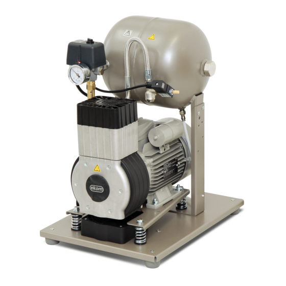
- Page 10 PRODU UCT DESRI PTION Fig. 2 : DK50-10Z Z/M – Comp pressor wit th dryer 07/2019 NP-DK50-10-A A -1_07-2019- -MD...
- Page 11 PROD D UCT DESR RIPTION Fig. 3: Com mpressor D K50-10S/M M (8-10bar) P-DK50-10-A-1 1_07-2019-MD 07/2019...
-
Page 12: Table Of Contents
TECHN NICAL DATA TECHN NICAL DATA Compre essors are designed to operate in dry, ve entilated an nd indoor d dust-free ro ooms with followin g climatic c conditions: Tempe erature from +5°C C to +40°C Relati ve humidit max. Working g pressure 5 5 –... - Page 13 TECHNICA AL DATA Working pre essure 6 – 8 DK50-10Z DK50 0-10S DK50-10Z/M DK50-1 10S/M Nominal volta 230, 230, 115, 230, 230, 115, Frequency 50/60 50/60 50/60 50/60 Capacity at 5 5 bar l/min 70/80 70/80 60/70 60/70 FAD) Working pres ssure 6.0 –...
-
Page 14: (L Pa )
TECHN NICAL DATA Workin ng pressure e 8 – 10 bar 50-10Z DK50-10S DK50- -10Z/M DK50-10S/M Nomina al voltage 230, 115, 230, 230, 115, 230, Freque ency 50/60 50/60 50/60 50/60 Capaci ity at 5 bar l/mi 60/70 60/70 50/60 50/60 (FAD) Workin... - Page 15 TECHNICA AL DATA AD correcti ion of capa acity for alt titude apacity give en in the for m of FAD („ „Free Air De elivery“) ap plies to the following co onditions: titude 0 m.n.m. Temper rature 20°C mospheric pressure 101325 Pa Relative...
- Page 16 INSTAL LLATION INSTAL LLATION Risk of i incorrect in nstallation. Only a qualified profession nal can in stall the c compresso or and pla ace it into operatio on for the f first time. H His obligat ion is to tr rain the ope erating per rsonnel on...
- Page 17 INSTAL LATION Prio or to instal llation, ens sure that th he compres ssor is free e of all tran nsport pac ckaging d stabilizer rs to avoid any risk of f damage t to the prod uct. move fixing g elements s of the pu umps once...
- Page 18 INSTAL LLATION Fig. 7 : Connectio on of cond densate col llection ves ssel Rout te the hose through the e opening in n the rear w wall of the ca abinet for c compressor models wit dryer r and conne ect it to the vessel.
- Page 19 INSTAL LATION 12.2. Co nnecting a a compress sor installe ed in a cabi Route the mains plug g through th he opening in the rear r wall of the e cabinet fo or cabinet-m mounted compresso ors. Connect t he cabinet DK50-10S...
- Page 20 INSTAL LLATION 14. PNE EUMATIC A AND ELECT TRICAL DIA AGRAMS 14.1 1. Pneuma atic diagram DK50- -10Z, DK50 0-10S DK50- -10Z/M, DK K50-10S/M Descri iption to pne eumatic dia agrams Inlet filter Safet ty valve Compress 10 Air ta 11 Drain n valve Relief valv...
- Page 21 INSTAL LATION 14.2. Ele ectrical diag grams K50-10Z, D K50-10S 5 - 7 bar, 6 - 8 b bar, 8 - 10 b N/PE 230 V, 5 0/60 Hz 115 V, 6 0 Hz ECTRICAL OBJ JECT OF 1st. C CAT.
- Page 22 INSTAL LLATION DK50- -10Z/M, DK K50-10S/M 5 - 7 bar, 6 6 - 8 bar 1/N/PE 230 V, 50/60 115 V, 60 Hz ELECTR RICAL OBJECT T OF 1st. CAT. 07/2019 NP-DK50-10-A A -1_07-2019- -MD...
- Page 23 INSTALLATION DK50-10Z/M M, DK50-10 0S/M 8 - 10 0 bar /N/PE 230 V , 50/60 Hz 115 V , 60 Hz ELECTRICAL O OBJECT OF 1st. . CAT. J** - Conne ect the jump per only for r compress or 1 Comp pressor models not installed in...
- Page 24 INSTAL LLATION Comp pressor cab binet DK50 -10S/M 8 – 10 bar 1/N/PE 230 V, 50/60 ELECTR RICAL OBJECT OF 1st. CAT. Descr iption to el lectrical dia agrams Compre essor motor acitor Compre essor fan Pres ssure switch Dryer fa Term minal block Relief va...
- Page 25 OPER RATION PERATION E EQUIPME ENT MAY O ONLY BE O OPERATED D BY THE T TRAINED S STAFF! sk of electr ic shock In c case of any y danger, d disconnect t the comp pressor fro om the mai ns (pull ou ut the ins plug).
- Page 26 OPERA ATION 15. SWT TICHNING ON THE C OMPRESS Start t the compr ressor (with hout a cabin net) at the p pressure sw witch (1) by y turning the e switch (2) ) to posit tion “I.” Th his starts th e compress sor and fills...
- Page 27 PRODUC CT MAINTE ENANCE RODUCT M MAINTENAN 7. PRODUC CT MAINTEN NANCE e operator should ca rry out dev vice check ks regularly y in the inte ervals defi ned by plicable reg gulations. T Test result ts must be recorded.
- Page 28 PRODU UCT MAINT TENANCE 17.1 1. Mainten nance interv vals operator qualified t t echnician 07/2019 NP-DK50-10-A A -1_07-2019- -MD...
- Page 29 PRODUC CT MAINTE ENANCE 17.2. Ch eck of prod duct opera ation Check pum mp conditio n – the pum mps must o operate eve nly without excessive vibrations o or noise. If there is a any negativ e result, fin d the cause e of the give en condition...
- Page 30 PRODU UCT MAINT TENANCE 17.5 5. Conden nsate drain Compre essors Open th e drain val lve carefull ly and slow wly. If the d drain valve is opened too much, it is acc companied by high n noise level and uncon ntrolled jet t of the ac...
- Page 31 PRODUC CT MAINTE ENANCE 17.6. Ch eck of safe ety valve Turn the screw (2) o on the safety y valve (1) s several times to t the left until the safety valve relea ses the air. Let the sa afety valve vent for a fe ew seconds...
- Page 32 PRODU UCT MAINT TENANCE Dism mantle the fi lter elemen t (4) by pull ling it downw wards. Inser rt a new filte er element. Moun nt the filter bowl. Sligh htly tighten t the filter bow wl using a w wrench.
- Page 33 PRODUC C T MAINTE E NANCE g. 15 P-DK50-10-A-1 1_07-2019-MD D 3 36 07/2019...
- Page 34 PRODU UCT MAINT TENANCE g. 16 Installin ng the jum per: Disco onnect the product from m the mains s by pulling the plug ou ut of the soc cket. Rem move the cov ver on the e electrical pa anel (on the compresso...
- Page 35 PRODUC CT MAINTE ENANCE ompressor - when op perating out tside the c cabinet, the e electrical connection n with an installed mper must be created 17.11. Pro ocedure fo r connectin ng a comp ressor to a a new cabin Prio or to any maintena...
- Page 36 PRODU UCT MAINT TENANCE Conn nect the ca abinet to the e compress sor by inse rting the po ower cord w with conne ctor (1) into powe er socket (2 2). (Fig. 8) Conn nect the dev vice to the e electrical m ains...
- Page 37 PRODUC CT MAINTE ENANCE 17.12. Cle eaning of th he exterior r surfaces o of the prod duct se neutral a gents for cl eaning of th he external surfaces of f the produc e use of ag ggressive cleaning a agents and d comprisi ng alcoho...
- Page 38 TROUB BLESHOOT TING TROUB BLESHOOT TING Risk of e electric sho ock. Before a any of the e following g operation ns on the device, dis sconnect t the device from the e mains (pu ull out the m mains plug Risk of i injury durin ng work wi...
- Page 39 OUBLESHO OOTING ompressor Worn piston ring Replac e worn pisto on ring irty inlet filte Replac e dirty filter r with new fi lter ncorrect func ction of sole enoid valve Repair or replace f fan or coil amaged pis ston bearing g, piston Replac...
- Page 40 INHALT INHALT ALLGE EMEINE INF FORMATIO ONEN ....................44 1. KONFOR RMITÄT MIT T DEN ANF ORDERUN NGEN DER EU ..........4 44 2. SYMBOL E ..........................
-
Page 41: Konfor Rmität Mit
LGEMEINE INFORMAT TIONEN LLGEMEIN E INFORMA ATIONEN esen Sie da as Benutzer rhandbuch vor der Nu utzung des Produkts s sorgfältig du urch und be ewahren e es auf. Das Benu utzerhandbu uch enthält t Anleitung en zur ko rrekten Nu utzung, Inst tallation, edienung un... -
Page 42: Nutzung
ALLGE EMEINE INF FORMATIO ONEN Sicherung Etikett für r die Handh habung der Verpackung g – zerbrec chlich Etikett für r die Handh habung der Verpackung g – diese S eite nach o oben Etikett für r die Handh habung der Verpackung g –... -
Page 43: Allgeme Eine Sich
LGEMEINE INFORMAT TIONEN nzig der Be enutzer/Bed iener trägt a alle Risiken ALLGEM EINE SICH ERHEITSA ANWEISUN as Produkt w wurde entw wickelt und h hergestellt, um alle Ris siken in Ver bindung mit t seiner Nut tzung zu nimieren. D Das Produk kt ist für de en Benutze... - Page 44 ALLGE EMEINE INF FORMATIO ONEN 5. LAG GERUNGS- - UND TRA ANSPORTB EDINGUNG Der Her rsteller vers sendet den Kompresso or in einer T Transportve erpackung. Diese schü ützt das Ge erät während d des Trans sports vor S Schäden. Beschäd digungsgef fahr für Pn...
-
Page 45: Produ Uktschre Eibung
PRODU UKTSCHRE EIBUNG RODUKTSC CHREIBUN MODELL er Kompres sor wurde g gemäß sein nem Verwen ndungszwec ck in den fo olgenden Mo odellen erb aut: DK50-10Z Kompressor r auf Sockel für unabhä ängige Insta allation in R Räumen DK50-10Z/M Kompressor r auf Sockel mit Lufttroc ckner... - Page 46 PRODU UKTSCHRE EIBUNG alle obe en aufgefüh rten Kompr ressoren. Verwendun Filter rungsgrad /µm/ Druckregle Artikelnr. FS 20 4470 000001-043 FS 20 5+ 0,3 Nein 4470 000001-044 FS 20 DK50-10Z 5 + 0,3 4470 000001-071 FS 20 5+ 0,3 + 0,0 Nein 4470 000001-045...
- Page 47 PRODU UKTSCHRE EIBUNG 8.3. mpressorg gehäuse bb. 3 Das s challdichte Gehäuse d dient zur ko ompakten A Abdeckung d des Kompre essors. Gle eichzeitig ewährt es e einen ausre eichenden L Luftaustaus ch und däm mpft Geräu usche wirku ungsvoll.
- Page 48 PRODU UKTSCHRE EIBUNG Abb. 2 2: DK50-10 0Z/M – Kom mpressor m mit Trockne e r 07/2019 NP-DK50-10-A A -1_07-2019- -MD...
- Page 49 PRODU U KTSCHRE EIBUNG Abb. 3: Kom mpressorg ehäuseDK 50-10S/M ( (8–10 bar) P-DK50-10-A-1 1_07-2019-MD 07/2019...
-
Page 50: Techn Nische Da Aten
TECHN NISCHE DA ATEN TECHN NISCHE DA ATEN Die Kom mpressoren n sind für de en Betrieb in trockene en, belüftete en und stau ubfreien Inn nenräumen den folg genden klim matischen B edingungen n vorgesehe Tempe eratur von +5 °C bis +40 °C Relati ve Feuchti... - Page 51 CHNISCHE DATEN Arbeitsdruck k 6–8 bar DK50-10Z DK50 0-10S DK50-10Z/M DK50-1 10S/M Nennspannun Frequenz 50/60 50/60 50/60 50/60 Kapazität bei 5 bar l/min 70/80 70/80 60/70 60/70 FAD) Arbeitsdruck 6,0 – 8,0 6,0 – – 8,0 6,0 – 8,0 6,0 – –...
- Page 52 TECHN NISCHE DA ATEN Arbeits sdruck 8–10 0 bar 50-10Z DK50-10S DK50- -10Z/M DK50-10S/M Nennsp pannung Freque 50/60 50/60 50/60 50/60 Kapazi ität bei 5 bar l/mi 60/70 60/70 50/60 50/60 (FAD) Arbeits sdruck 8,0 – – 10,0 8,0 – 10,0 8,0 –...
- Page 53 CHNISCHE DATEN AD-Kapazit tätskorrekt ur für Höhe enagen e Kapazitä ät in Form von FAD („Free Air r Delivery“, , freie Dru uckluftverso rgung) gilt für die genden Be dingungen: Hö öhenlage 0 m.n.m. Temper ratur 20 °C mgebungsd ruck 101325 Pa Relative e Feuchtigk...
-
Page 54: Instal Llation
INSTAL LLATION INSTAL LLATION Risiko v von Installa ationsfehle Der Kom mpressor d darf aussc chließlich d durch eine e hierfür q ualifizierte e Fachkraft installie Betrieb genomm werd den. Dies erpflichtet, professi ionelles Be edienperso onal bzgl. d der Nutzun ng und Wa artung des Geräts zu... - Page 55 INSTAL LATION ellen Sie vor der Installatio on sicher, , dass d der Kompr ressor fre ei von rpackungs material u und Stabi lisatoren ist, um Schäden am Produ ukt zu rmeiden. tfernen Sie e die Befes stigungsele emente de r Pumpen, , nachdem der Komp...
- Page 56 INSTAL LLATION 11.2 2. Anschlu uss des Ko ondensatau uffangbehä älter Schli ießen Sie bei Komp pressoren mit Trockn nern den Kondensat tablaufschla auch an d Kond densatbehä älter an(Abb b. 7) Abb. 7 7: Anschlu ss des Kon ndensatauf ffangbehäl lter...
- Page 57 INSTAL LATION 12.1. An schließen eines Kom mpressors o ohne Gehä äuse Stecken S ie den Netz zstecker in e eine Steckd dose mit ent tsprechende er Spannun Der Kompr ressor ist nu un betriebs bereit. 12.2. An schließen eines Kom mpressors m...
- Page 58 INSTAL LLATION 14. DRU UCKLUFT- UND ELEK KTROSCHA AL TPLÄNE E 14.1 1. Drucklu uftplan DK50- -10Z, DK50 0-10S DK50- -10Z/M, DK K50-10S/M Besch hreibung des s Druckluftp plans Ansaugfilt Siche erheitsventi Kompress 10 Druc kluftbehälte Lüfter 11 Ablas ssventil Entlüftung gsventil 12 Kühle...
- Page 59 INSTAL LATION 14.2. Ele ektroschalt tpläne K50-10Z, D K50-10S 5 – 7 bar, 6 – 8 8 bar, 8 – 1 0 bar N/PE 230 V, 5 0/60 Hz 115 V, 6 0 Hz EKTRISCHE OB BJEKTKLASSE 1* – Stunde nzähler nur r für das Ko ompressorm...
- Page 60 INSTAL LLATION DK50- -10Z/M, DK K50-10S/M 5 – 7 bar, 6 – 8 bar 1/N/PE 230 V, 50/60 115 V, 60 Hz ELEKTR RISCHE OBJEK KTKLASSE 1 07/2019 NP-DK50-10-A A -1_07-2019- -MD...
- Page 61 INSTALLATION DK50-10Z/M M, DK50-10 0S/M 8 bis s 10 bar /N/PE 230 V, 50/60 Hz 115 V, 60 Hz ELEKTRISCHE OBJEKTKLASS SE 1 J** - Schli ießen Sie den Jum per nur f ür 1 – Kom mpressor Kompressor rmodelle oh hne Gehäus se an.
- Page 62 INSTAL LLATION Komp pressorgeh häuse DK50 0-10S/M 8 – 10 bar 1/N/PE 230 V, 50/60 ELEKTR RISCHE OBJEK KTKLASSE 1 Besch hreibung de er Elektros chaltpläne Kompres ssormotor Kond densator Kompres ssorlüfter Druc ckschalter Trockne erlüfter Klem mmblock Entlüftun ngsventil Tren nnschalter Tempera...
- Page 63 ETRIEB ETRIEB S GERÄT D DARF NUR R DURCH G GESCHULT TES PERSO ONAL BEDI IENT WERD DEN! Stro omschlagg gefahr ennen Sie b bei Gefahr den Komp ressor vom m Stromnet tz (Netzste ecker ziehe rbrennungs s- oder Bra andgefahr.
- Page 64 BETRIE 15. EIN SCHALTEN N DES KOM MPRESSOR Start ten Sie den Kompress or (ohne Ge ehäuse) am m Drucksch alter (1), ind dem Sie de en Schalter Position „I “ stellen. D Dadurch w wird der Ko ompressor gestartet und der T Tank bis z...
- Page 65 ODUKTWA ARTUNG RODUKTWA ARTUNG 7. PRODUK KTWARTUN r Bediener muss die Geräte in den vorge eschriebene en Interval llen kontro ollieren. e Prüfergeb bnisse müs ssen aufge zeichnet w werden. as Gerät wu urde konstr ruiert und h hergestellt, u um den Wa artungsaufw wand gering...
- Page 66 PRODU UKTWARTU 17.1 1. Wartung gsintervalle iener Qualifizierter Techniker 07/2019 NP-DK50-10-A A-1_07-2019- -MD...
- Page 67 ODUKTWA ARTUNG 17.2. Pro oduktbetrie eb überprü Pumpenzu ustand prüfe en – die P Pumpen mü üssen norm mal, ohne ü übermäßige e Schwingu ng oder Geräusche entwicklung g laufen. Su chen Sie be ei negativen n Prüfergeb bnissen die Ursache da afür oder rufen Sie e...
- Page 68 PRODU UKTWARTU Über rprüfen Sie, ob die Kab bel am Ansc chlusskaste en angeschl lossen sind (Sichtprüfu ung). Über rprüfen Sie alle Schrau ubverbindun ngen der grü ün-gelben P PE-Erdungs sleiter. 17.5 5. Konden nsatablauf Kompre essor Öffnen S Sie das Ab blassventil vorsichtig...
- Page 69 ODUKTWA ARTUNG 17.6. Sic cherheitsve entil überp rüfen Drehen S Sie die Schr raube (2) am m Sicherhei itsventil (1) mehre ere Umdreh hungen nac h links, bis Sicherhe itsventil Luf ft ablässt. Das Sich erheitsvent til einige Se kunden aus sblasen lassen.
- Page 70 PRODU UKTWARTU Entfe ernen Sie d en Schlauc ch (1) aus de er Schnellk upplung. Löse en Sie den F Filterbecher r (3) mithilfe e eines Sch raubenschl üssels und bauen Sie ihn aus. Baue en Sie das F Filterelemen nt (4) aus, i ndem Sie e...
- Page 71 PRO O DUKTWA A RTUNG bb. 15 P-DK50-10-A-1 1_07-2019-MD D 7 74 07/2019...
- Page 72 PRODU UKTWARTU bb. 16 Installie eren des Ju umpers: Tren nen Sie das s Gerät vom m Stromnetz z, indem Si e den Steck ker aus der r Steckdose e ziehen. Entfe ernen Sie d ie Abdecku ng von der Schalttafel (des Komp pressors).
- Page 73 ODUKTWA ARTUNG ompressor – – Bei einem m Betrieb au ußerhalb de s Schaltsch hranks mus ss die elektr rische Verb indung thilfe eines Jumpers h ergestellt w werden. 17.11. Vorgehen nsweise z um Ansch hließen ei ines Kom pressors an einen neuen Schal...
- Page 74 PRODU UKTWARTU Verb binden Sie den Scha ltschrank m mit dem K Kompressor , indem S ie den Ste ecker (1) d Netz zkabels in di ie Steckdos se (2) steck en. (Abb. 8 Schli ießen Sie d das Gerät an n das Strom mnetz an...
- Page 75 ODUKTWA ARTUNG 17.12. Re inigung vo on Produkta außenfläch ur Reinigung g der Produ uktaußenfläc chen nur ne eutrale Mitte el benutzen wendung v von Alkoh hol und Ch hlorid enth haltenden aggressive en Reinigu ungs- tteln kann z zur Produk ktoberfläch henbeschäd digungen u...
- Page 76 FEHLE RBEHEBU FEHLE RBEHEBU Stromsc chlaggefah Trennen n Sie das G Gerät von der Strom mversorgun ng (Netzste ecker zieh en), bevor Sie eine der folgen nden Arbeit ten am Ger rät ausführ ren. rbeiten Druckluft tkomponen nten unte Druck besteht Verletzu ungsgefahr...
- Page 77 EHLERBEH HEBUNG Verbind dungen fest tziehen iedrige Pum mpenkapazi ität Pumpe e reinigen od der austaus schen umpenstöru Pumpe e reinigen od der austaus schen rocknerstör rung Trockne er austausc chen Pneum atiksystem überprüfen n – lose uftaustritt im m Pneumati ksystem Verbind dungen fest...
- Page 78 /ANNEX / ANHANG / PRÍLOHA ANNEX / ANHANG / PRÍLOHA 21. INSTALLATION RECORD 1. Product: (model) 2. Serial number: DK50-10Z DK50-10S DK50-10Z/M DK50-10S/M 3.1. User’s name: 3.2. Address of installation: 4. Equipment connected to the compressor: 5. Installation / Commissioning: 6.
- Page 79 /ANNEX / ANHANG / PRÍLOHA 21. INSTALLATIONSPROTOKOLL 1. Produkt: (Modell) 2. Seriennummer: DK50-10Z DK50-10S DK50-10Z/M DK50-10S/M 3.1. Benutzername: 3.2. Aufstellungsort: 4. An den Kompressor angeschlossene Geräte: 5. Installation / Inbetriebnahme: 6. Inhalte der Bedienerschulung: Vollständigkeitsprüfung des Produkts** Beschreibung Produkts Funktionen** Dokumentation der Vollständigkeitsprüfung** Produktbetrieb: Ein-/Ausschalten, Steuerungen, Steuerungsabläufe, Daten auf dem Display,...
- Page 80 DK50-10 EKOM spol. s r.o., Priemyselná 5031/18, 921 01 PIEŠŤANY, Slovak Republic tel.: +421 33 7967255, fax: +421 33 7967223 e-mail: ekom@ekom.sk, www.ekom.sk NP-DK50-10-A-1_07-2019-MD 112000429-000...
Need help?
Do you have a question about the DK50-10 Series and is the answer not in the manual?
Questions and answers