EKOM DK50 4VR/50 User Manual
Hide thumbs
Also See for DK50 4VR/50:
- Installation, operation and maintenance manual (27 pages) ,
- Installation, operation and maintenance manual (84 pages) ,
- User manual (392 pages)
Table of Contents
Advertisement
Available languages
Available languages
Quick Links
Advertisement
Chapters
Table of Contents

Related Manuals for EKOM DK50 4VR/50


Summary of Contents for EKOM DK50 4VR/50
- Page 1 USER MANUAL BENUTZERHANDBUCH NÁVOD NA POUŽITIE...
- Page 3 COMPRESSOR DK50 4VR/50 KOMPRESSOR DK50 2x4VR/110 KOMPRESOR EKOM spol. s r. o. Priemyselná 5031/18 SK-921 01 Piešťany Slovak Republic tel.: +421 33 7967255 fax: +421 33 7967223 www.ekom.sk email: ekom@ekom.sk DATE OF LAST REVISION DATUM DER LETZTEN ÜBERARBEITUNG 08/2021 DÁTUM POSLEDNEJ REVÍZIE...
- Page 4 CONTENTS ....................5 INHALT ......................56 OBSAH ......................109...
-
Page 5: Table Of Contents
CONTENTS CONTENTS GENERAL INFORMATION ......................6 CONFORMITY WITH THE REQUIREMENTS OF THE EUROPEAN UNION ....6 SYMBOLS ........................6 DEVICE USE ........................7 GENERAL SAFETY INSTRUCTIONS ................7 STORAGE AND TRANSPORT CINDITIONS ..............9 PRODUCT DESCRIPTION ......................10 VARIANTS ........................10 ACCESSORIES ...................... -
Page 6: General Information
GENERAL INFORMATION GENERAL INFORMATION Carefully read this user manual before using the product and carefully store it for future reference. The user manual aids in the proper use, including installation, operation and maintenance, of the product. The user manual corresponds to the configuration of the product and its compliance with applicable safety and technical standards at the time of its printing. -
Page 7: Device Use
GENERAL INFORMATION Fuse Package handling label – fragile Package handling label – this side up Package handling label – keep dry Package handling label – temperature limits Package handling label – limited stacking Package label – recyclable material Manufacturer 3. DEVICE USE 3.1. - Page 8 GENERAL INFORMATION the instructions stated below are followed. 4.1. Required qualification of the personnel Each user must be trained by the manufacturer or an organization authorized by the manufacturer or instructed on the device operation by other trained user. ...
-
Page 9: Storage And Transport Cinditions
GENERAL INFORMATION 5. STORAGE AND TRANSPORT CINDITIONS The compressor is shipped from the manufacturer in transport packaging. This protects the product from damage during transport. Potential for damage to pneumatic components. The compressor must be transported only when all air has been vented. Before moving or transporting the compressor, release all the air pressure from the tank and pressure hoses, from dryer chambers and drain condensate from the tank and from the condensate separator on the dryer. -
Page 10: Product Description
PRODUCT DESCRIPTION PRODUCT DESCRIPTION 6. VARIANTS The compressor is manufactured according to its intended application in the following variants: DK50 4VR/50 Compressor for installation in areas where operations will not disturb the surroundings DK50 4VR/50/M Compressor with a membrane air dryer... -
Page 11: Accessories
The automatic condensate drain (AOK) automatically drains condensate from the compressor’s air tank based on a pre-set time interval. The condensate drain (AOK) is a suitable accessory for compressor models without dryers. Type Article number AOK 18 DK50 4VR/50 604014082-000 AOK 19 DK50 2x4VR/110 604014083-000 Set of compressed air outlet filters The compressor may be equipped with a set of filters if specified. -
Page 12: Product Function
PRODUCT DESCRIPTION Equipotential bonding socket The socket allows an equipotential bonding. Type Name Article number DK50 4VR/50 POAG-KBT6-EC Mains plug connector 033400075-000 DK50 4VR/50/M DK50 2x4VR/110 FLEXI-S/POAG-HK6 Conductor (1 m) 034110083-000 DK50 2x4VR/110/M 8. PRODUCT FUNCTION 8.1. Compressor The air pump (1) draws in atmospheric air through an inlet filter (8) and compresses it through a non-return valve (3) into an air tank (2) from which the device draws compressed air. - Page 13 28 Power cord 12 Condensate collection vessel 29 Cabinet gas springs 13 Magnetic holder 30 Connecting reinforcement 14 Compressed air outlet 31 Maintenance indicator 15 Compressor wheel Fig. 1: Compressor with membrane dryer DK50 4VR/50/M 08/2021 NP-DK50 4VR 50, DK50 2x4VR 110-A-2_08-2021-MD...
- Page 14 PRODUCT DESCRIPTION DK50 2x4VR/110/M NP-DK50 4VR 50, DK50 2x4VR 110-A-2_08-2021-MD 08/2021...
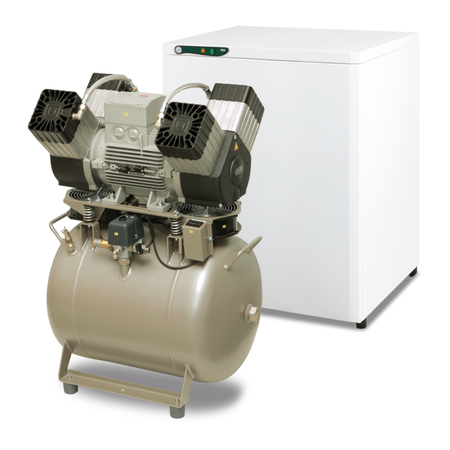
- Page 15 PRODUCT DESCRIPTION Fig. 2: Compressor DK50 4VR/50 DK50 2x4VR/110 08/2021 NP-DK50 4VR 50, DK50 2x4VR 110-A-2_08-2021-MD...
- Page 16 PRODUCT DESCRIPTION Fig. 3: Cabinet A - DK50 4VR/50S NP-DK50 4VR 50, DK50 2x4VR 110-A-2_08-2021-MD 08/2021...
- Page 17 PRODUCT DESCRIPTION B - DK50 2x4VR/110S 08/2021 NP-DK50 4VR 50, DK50 2x4VR 110-A-2_08-2021-MD...
-
Page 18: Technical Data
TECHNICAL DATA TECHNICAL DATA Compressors are designed for operation in dry, ventilated and dust-free indoor rooms under the following climactic conditions: +5°C to +40°C Temperature Relative humidity max. 70% DK50 DK50 DK50 DK50 Working pressure 6 – 8 bar 4VR/50 4VR/50S 4VR/50/M 4VR/50S/M... - Page 19 TECHNICAL DATA DK50 DK50 DK50 DK50 Working pressure 8 – 10 bar 4VR/50 4VR/50S 4VR/50/M 4VR/50S/M Nominal voltage V, Hz 3x400, 50 3x400, 50 3x400, 50 3x400, 50 Frequency Capacity at 8 bar l/min (FAD) 8.0 – 10.0 8.0 – 10.0 8.0 –...
- Page 20 TECHNICAL DATA DK50 DK50 DK50 DK50 Working pressure 6 – 8 bar 2x4VR/110 2x4VR/110S 2x4VR/110/M 2x4VR/110S/M Nominal voltage V, Hz 3x400, 50 3x400, 50 3x400, 50 3x400, 50 Frequency Capacity at 6 bar l/min (FAD) 6.0 – 8.0 6.0 – 8.0 6.0 –...
- Page 21 TECHNICAL DATA DK50 DK50 DK50 DK50 Working pressure 8 – 10 bar 2x4VR/110 2x4VR/110S 2x4VR/110/M 2x4VR/110S/M Nominal voltage V, Hz 3x400, 50 3x400, 50 3x400, 50 3x400, 50 Frequency Capacity at 8 bar l/min (FAD) 8.0 – 10.0 8.0 – 10.0 8.0 –...
- Page 22 TECHNICAL DATA FAD correction of capacity for altitude Capacity given in the form of FAD („Free Air Delivery“) applies to the following conditions: 20°C Altitude 0 m.n.m. Temperature Atmospheric pressure 101325 Pa Relative humidity To calculate FAD compressor capacity in dependence on altitude, it is necessary to apply correction factor according to the following table: Altitude [m.n.m.] 0 -1500...
-
Page 23: Installation
INSTALLATION INSTALLATION Risk of incorrect installation. Only a qualified technician may install the compressor and place it into operation for the first time. Their duty is to train operating personnel on the use and maintenance of the equipment. An entry is made in the equipment installation record to certify installation and operator training. - Page 24 INSTALLATION Fig. 4: Handling the compressor DK50 4VR/50 DK50 2x4VR/110 Remove the transport stabilisers from the air pumps (Fig. 5). Prior to installation, ensure that the compressor is free of all transport packaging and stabilizers to avoid any risk of damage to the product.
- Page 25 INSTALLATION Fig. 5: Releasing the air pumps DK50 4VR/50 DK50 2x4VR/110 10.2. Placement of the compressor in the cabinet DK50 4VR/50S (Fig. 2-A): Disassembly cabinet door Remove the door held by 2 screws and disconnect the earthing lead. Compressor placement ...
- Page 26 INSTALLATION Place the connecting strip (30) in its original position in the lower part of the cabinet. Cabinet door installation Align the door with the cabinet, connect the earthing lead to the door and mount the door to the cabinet using 2 fasteners.
- Page 27 INSTALLATION Fig. 6: Placement of the compressor in the cabinet 10.3. Valve installation on the condensate drain from the cabinet (DK50 2x4VR/110) For cabinet-mounted compressors, install the threaded fitting with the valve (1) into the hole in the side of the cabinet and install the PA Ø 8 / Ø 6 hose (2). Insert the other side of the hose into the fitting (4) beneath the air tank from which the valve (3) and hose are removed.
-
Page 28: Pneumatic Connection
Route the pressure hose from the compressed air outlet (1) to the connected equipment. Route the pressure hose through the opening in the rear wall of the cabinet for cabinet- mounted compressors. A G 3/8" (DK50 4VR/50), G1/2" (DK50 2x4VR/110) connection is installed. DK50 4VR/50 DK50 2x4VR/110 Fig. - Page 29 INSTALLATION DK50 4VR/50 DK50 2x4VR/110 Fig. 9: Connecting the cabinet pressure gauge to the compressor Condensate outlet from dryer Do not connect the condensate drain directly to a waste drain! Passers-by may be injured! Connect a hose to the outlet from the automatic condensate drain to drain piping or to the provided condensate collection vessel.
-
Page 30: Electrical Connection
INSTALLATION 11.3. Routing hoses and electrical cables in cabinet-mounted compressors Route the hose and electrical cables through the opening in the rear wall of the cabinet for compressor models with a dryer. Risk of damage to pneumatic components. Air hoses must not be broken. 12. -
Page 31: Commissioning
INSTALLATION 12.2. Connecting a compressor installed in a cabinet Route the mains plug through the opening in the rear wall of the cabinet for cabinet-mounted compressors. (Fig. 12) Connect the cabinet electrically to the compressor by inserting the provided power cord with connector into an outlet. -
Page 32: Pneumatic And Electrical Diagrams
INSTALLATION Check connection of the cabinet manometer hose to the pneumatic block of the compressor (Fig. Check to ensure the hose from the automatic condensate drain is connected to the condensate collection vessel. (Fig. 10). The compressor is not equipped with a backup power supply. 14. - Page 33 INSTALLATION DK50 4V/50/M 08/2021 NP-DK50 4VR 50, DK50 2x4VR 110-A-2_08-2021-MD...
- Page 34 INSTALLATION DK50 2x4VR/110 NP-DK50 4VR 50, DK50 2x4VR 110-A-2_08-2021-MD 08/2021...
- Page 35 INSTALLATION DK50 2x4VR/110/M 08/2021 NP-DK50 4VR 50, DK50 2x4VR 110-A-2_08-2021-MD...
- Page 36 Air tank 18 Filter Pressure gauge 19 Microfilter 10 - 14.2. Electrical diagrams 6 - 8 bar, 8 – 10 bar DK50 4VR/50 3/N/PE~400V, 50Hz ELEKTRIC MAIN TN-S [TN-C-S] ELEKTRIC OBJECT OF 1st. CAT. NP-DK50 4VR 50, DK50 2x4VR 110-A-2_08-2021-MD 08/2021...
- Page 37 INSTALLATION 6 - 8 bar, 8 – 10 bar DK50 4VR/50/M 3/N/PE~400V, 50Hz ELEKTRIC MAIN TN-S [TN-C-S] ELEKTRIC OBJECT OF 1st. CAT. 08/2021 NP-DK50 4VR 50, DK50 2x4VR 110-A-2_08-2021-MD...
- Page 38 INSTALLATION DK50 2x4VR/110 6 - 8 bar, 8 - 10 bar 3/N/PE~400V, 50Hz ELEKTRIC MAIN TN-S [TN-C-S] ELEKTRIC OBJECT OF 1st. CAT. NP-DK50 4VR 50, DK50 2x4VR 110-A-2_08-2021-MD 08/2021...
- Page 39 INSTALLATION DK50 2x4VR/110/M 6 - 8 bar, 8 - 10 bar 3/N/PE~400V, 50Hz ELEKTRIC MAIN TN-S [TN-C-S] ELEKTRIC OBJECT OF 1st. CAT. 08/2021 NP-DK50 4VR 50, DK50 2x4VR 110-A-2_08-2021-MD...
- Page 40 INSTALLATION Compressor cabinet 1/N/PE~230V, 50/60Hz ELEKTRIC OBJECT OF 1st. CAT. DK50 4VR/50 DK50 2x4VR/110 NP-DK50 4VR 50, DK50 2x4VR 110-A-2_08-2021-MD 08/2021...
- Page 41 INSTALLATION Description to electrical diagrams: M1, M2 Compressor motor Terminal box E1 – E4 Compressor fan Connector Fuse M11, M12 Dyer solenoid valve E5 – E8 F1, F2 Breaker Dryer fan Switch Pressure switch E10-13 Cabinet fan Temperature switch X10, X11 Connector Q11,12 Contactor...
-
Page 42: Operation
OPERATION OPERATION ONLY TRAINED PERSONNEL MAY OPERATE THE EQUIPMENT! Risk of electric shock. In case of emergency, disconnect the compressor from the mains (pull out the mains plug). Burn or fire hazard. Portions of the air pump may be hot and reach hazardous temperatures during compressor operation that may harm materials or operating staff. -
Page 43: Switching On The Compressor
OPERATION 15. SWITCHING ON THE COMPRESSOR Start the compressor (without a cabinet) at the pressure switch (1) by turning the switch (2) to position “I.” This starts the compressor and fills the tank to the switching off pressure, which then shuts off the compressor. -
Page 44: Product Maintenance
PRODUCT MAINTENANCE PRODUCT MAINTENANCE 17. PRODUCT MAINTENANCE The operator should carry out device checks regularly in the intervals defined by applicable regulations. Test results must be recorded. The equipment has been designed and manufactured to keep maintenance to a minimum. The following work must be performed to preserve the proper and reliable operation of the compressor. - Page 45 PRODUCT MAINTENANCE 17.1. Maintenance intervals operator qualified technician 08/2021 NP-DK50 4VR 50, DK50 2x4VR 110-A-2_08-2021-MD...
- Page 46 PRODUCT MAINTENANCE qualified technician NP-DK50 4VR 50, DK50 2x4VR 110-A-2_08-2021-MD 08/2021...
- Page 47 PRODUCT MAINTENANCE 17.2. Check of product operation Check air pump condition – the air pumps should be operating normally without excessive vibration or noise. Troubleshoot any problem or call in service personnel if trouble is detected. Visually inspect fan operation – the fans must be operating when the air pumps are running. Troubleshoot any problem or call in service personnel if trouble is detected.
- Page 48 PRODUCT MAINTENANCE Visually check if cables are connected to the terminal box. Check all screw connections of the green-yellow PE grounding conductor. 17.5. Condensate drain Condensate may accumulate in the air tank if the dryer malfunctions. Follow this procedure to remove this condensate: Switch off the compressor at the mains.
- Page 49 PRODUCT MAINTENANCE Before the following checks it is required: For compressor variant with cabinet – unlock the door lock and open the cabinet door. 17.6. Check of safety valve Turn the screw (2) on the safety valve (1) several times to the left until the safety valve releases the air.
- Page 50 PRODUCT MAINTENANCE 17.8. Filter element replacement Remove the hose (1) from the quick connector. Use a wrench (2) to release the filter vessel (3) and remove. Pull down on the filter element (4) to remove. Insert a new filter element. ...
- Page 51 Close the fuse cover – D. Reinstall the cover on the electrical panel. Connect the device to the electrical mains. Activate the compressor by turning on the switch on the pressure switch. Fig. 20: DK50 4VR/50/M 400V Fig. 21: DK50 2x4VR/110 08/2021...
- Page 52 PRODUCT MAINTENANCE 400 V 17.11. Procedure for connecting a compressor to a new cabinet Prior to any maintenance or repair work, switch off the compressor and disconnect it from the mains (pull out the mains plug). The compressor in a cabinet requires that the jumper is not mounted in the terminal strip for correct operation (Fig.
-
Page 53: Long-Term Shutdown
PRODUCT MAINTENANCE Connect the cabinet to the compressor by inserting the power cord with connector into a power socket. (Fig. 13) Connect the device to the electrical mains Activate the compressor by turning on the switch on the pressure switch and the switch (4) on the cabinet (Fig. -
Page 54: Troubleshooting
TROUBLESHOOTING TROUBLESHOOTING Risk of electric shock. Before interfering with the equipment, first disconnect it from the mains (remove the power socket). Troubleshooting may only be performed by a qualified service technician. Damage to the safety valve could cause pressure to rise to hazardous levels. Never adjust a safety valve. -
Page 55: Repair Service
TROUBLESHOOTING Check the moisture content of the air exiting the air tank (see the Technical data chapter) to prevent damage to connected downstream equipment. 20. REPAIR SERVICE Warranty and post-warranty repairs must be done by the manufacturer, its authorized representative, or service personnel approved by the supplier. Attention. - Page 56 INHALT INHALT ALLGEMEINE INFORMATIONEN ....................57 KONFORMITÄT MIT DEN ANFORDERUNGEN DER EU ..........57 SYMBOLE ........................57 NUTZUNG DES GERÄTS ....................58 ALLGEMEINE SICHERHEITSANWEISUNGEN .............59 LAGERUNGS- UND TRANSPORTBEDINGUNGEN ............60 PRODUKTBESCHREIBUNG .......................61 VERSIONEN ........................61 ZUBEHÖR ........................62 PRODUKTFUNKTION ....................63 TECHNISCHE DATEN .........................70 INSTALLATION ...........................75 INSTALLATIONSBEDINGUNGEN .................75 ZUSAMMENBAU DES KOMPRESSORS ...............75 PNEUMATISCHER ANSCHLUSS ..................80 ELEKTRISCHER ANSCHLUSS ..................82...
-
Page 57: Allgemeine Informationen
ALLGEMEINE INFORMATIONEN ALLGEMEINE INFORMATIONEN Lesen Sie das Benutzerhandbuch vor der Nutzung des Produkts sorgfältig durch und bewahren Sie es auf. Das Benutzerhandbuch enthält Anleitungen zur korrekten Nutzung, Installation, Bedienung und Wartung des Produkts. Zum Zeitpunkt des Drucks entspricht das Benutzerhandbuch dem Produktdesign und erfüllt die geltenden Sicherheits- und Technikstandards. -
Page 58: Nutzung Des Geräts
ALLGEMEINE INFORMATIONEN Sicherung Etikett für die Handhabung der Verpackung – zerbrechlich Etikett für die Handhabung der Verpackung – diese Seite nach oben Etikett für die Handhabung der Verpackung – trocken lagern Etikett für die Handhabung der Verpackung – Temperaturgrenzwerte Etikett für die Handhabung der Verpackung – Stapelbeschränkung Verpackungsetikett –... -
Page 59: Allgemeine Sicherheitsanweisungen
ALLGEMEINE INFORMATIONEN 4. ALLGEMEINE SICHERHEITSANWEISUNGEN Das Produkt wurde entwickelt und hergestellt, um alle Risiken in Verbindung mit seiner Nutzung zu minimieren. Das Produkt ist für den Benutzer und die Umgebung sicher, wenn es gemäß seinem Verwendungszweck und den nachfolgend aufgeführten Anweisungen verwendet wird. 4.1. -
Page 60: Lagerungs- Und Transportbedingungen
ALLGEMEINE INFORMATIONEN 5. LAGERUNGS- UND TRANSPORTBEDINGUNGEN Der Kompressor wird ab Hersteller in einer Transportverpackung versendet. Diese schützt das Produkt während des Transports vor Schäden. Beschädigungsgefahr für Pneumatikkomponenten! Der Kompressor darf nur transportiert werden, wenn die gesamte Luft abgelassen wurde. Vor dem Bewegen oder Transportieren des Kompressors entlassen Sie jegliche Druckluft aus dem Behälter und den Druckschläuchen sowie aus den Trocknungskammern und lassen Sie das Kondensat aus dem Behälter und dem Kondensatabscheider am Trockner ab. -
Page 61: Produktbeschreibung
PRODUKTBESCHREIBUNG 6. VERSIONEN Der Kompressor ist gemäß seinem Verwendungszweck in den folgenden Modellen erhältlich: Kopressor für Installation in Bereichen, in denen der Betrieb die Umgebung DK50 4VR/50 nicht stört DK50 4VR/50/M Kompressor mit Membranlufttrockner Kompressor in einem Schaltschrank mit effektiver Geräuschdämpfung DK50 4VR/50S Kompressor mit Membrantrockner in einem Gehäuse... -
Page 62: Zubehör
Der automatische Kondensatablauf (Automatic Condensate Drain; AOK) lässt das Kondensat automatisch und gemäß einem vorgegebenen Zeitintervall aus dem Kompressor-Luftbehälter ab. Der Kondensatablauf (AOK) ist ein geeignetes Zubehörteil für Kompressormodelle ohne Trockner. Verwendung Artikelnummer AOK 18 DK50 4VR/50 604014082-000 AOK 19 DK50 2x4VR/110 604014083-000 Satz mit Druckluft-Ausgangsfiltern Der Kompressor kann, sofern angegeben, mit einem Filtersatz ausgestattet werden. -
Page 63: Produktfunktion
PRODUKTBESCHREIBUNG Verwendung Artikelnummer DK50 4VR/50 Halterung für Kompressormontage 603014177-000 DK50 4VR/50/M Halterung für Kompressormontage 604014131-000 DK50 2x4VR/110 Halterung für Wandmontage DK50 2x4VR/110/M 603014120-000 Potenzialausgleichsbuchse Die Buchse ermöglicht einen Potenzialausgleich. Verwendung Name Artikelnummer DK50 4VR/50 POAG-KBT6-EC Netzstecke 033400075-000 DK50 4VR/50/M DK50 2x4VR/110... - Page 64 PRODUKTBESCHREIBUNG ausreichenden Kühlluftaustausch. Der Lüfter unter dem Kompressoraggregat (11) und die Schranklüfter (21) kühlen den Kompressor. Die Lüfter laufen gleichzeitig mit dem Kompressormotor oder wenn der Temperaturschalter bei einer Temperatur über 40 °C betätigt wird. Sobald sich die Temperatur im Schrank auf ca. 32 °C abgekühlt hat, werden die Lüfter automatisch ausgeschaltet. Überhitzungsgefahr des Kompressors! Stellen Sie sicher, dass der Einlass für die Kühlluft in das Gehäuse (im Bodenbereich des Gehäuses) und der Auslass für die Warmluft an der Rückseite...
- Page 65 PRODUKTBESCHREIBUNG Abb. 1: Kompressor mit Trockner DK50 4VR50/M 08/2021 NP-DK50 4VR 50, DK50 2x4VR 110-A-2_08-2021-MD...
- Page 66 PRODUKTBESCHREIBUNG DK50 2x4VR/110/M NP-DK50 4VR 50, DK50 2x4VR 110-A-2_08-2021-MD 08/2021...
- Page 67 PRODUKTBESCHREIBUNG Abb. 2: Kompressor DK50 4VR/50 DK50 2x4VR/110 08/2021 NP-DK50 4VR 50, DK50 2x4VR 110-A-2_08-2021-MD...
- Page 68 PRODUKTBESCHREIBUNG Abb. 3: Gehäuse A – DK50 4VR/50S NP-DK50 4VR 50, DK50 2x4VR 110-A-2_08-2021-MD 08/2021...
- Page 69 PRODUKTBESCHREIBUNG B – DK50 2x4VR/110S 08/2021 NP-DK50 4VR 50, DK50 2x4VR 110-A-2_08-2021-MD...
-
Page 70: Technische Daten
TECHNISCHE DATEN TECHNISCHE DATEN Die Kompressoren sind für den Betrieb in trockenen, belüfteten und staubfreien Innenräumen unter den folgenden klimatischen Bedingungen vorgesehen: +5 °C bis +40 °C Temperatur Relative Feuchtigkeit max. 70 % DK50 DK50 DK50 DK50 Arbeitsdruck 6 – 8 bar 4VR/50 4VR/50S 4VR/50/M... - Page 71 TECHNISCHE DATEN DK50 DK50 DK50 DK50 Arbeitsdruck 8 – 10 bar 4VR/50 4VR/50S 4VR/50/M 4VR/50S/M Nennspannung V, Hz 3x400, 50 3x400, 50 3x400, 50 3x400, 50 Frequenz Kapazität bei 8 bar l/min (FAD) 8,0 – 10,0 8,0 – 10,0 8,0 – 10,0 8,0 –...
- Page 72 TECHNISCHE DATEN DK50 DK50 DK50 DK50 Arbeitsdruck 6 – 8 bar 2x4VR/110 2x4VR/110S 2x4VR/110/M 2x4VR/110S/M Nennspannung V, Hz 3x400, 50 3x400, 50 3x400, 50 3x400, 50 Frequenz Kapazität bei 6 bar l/min (FAD) 6,0 – 8,0 6,0 – 8,0 6,0 – 8,0 6,0 –...
- Page 73 TECHNISCHE DATEN DK50 DK50 DK50 DK50 Arbeitsdruck 8 – 10 bar 2x4VR/110 2x4VR/110S 2x4VR/110/M 2x4VR/110S/M Nennspannung V, Hz 3x400, 50 3x400, 50 3x400, 50 3x400, 50 Frequenz Kapazität bei 8 bar l/min (FAD) 8,0 – 10,0 8,0 – 10,0 8,0 – 10,0 8,0 –...
- Page 74 TECHNISCHE DATEN FAD-Kapazitätskorrektur für Höhenlagen Die Kapazität in Form von FAD („Free Air Delivery“ = Volumenstrom bzw. Liefermenge) gilt für die folgenden Bedingungen: Höhenlage 0 m ü. M. 20 °C Temperatur Umgebungsdruck 101325 Pa Relative Feuchtigkeit Um die FAD-Kompressorkapazität in Abhängigkeit von der Höhenlage zu berechnen, muss der Korrekturfaktor gemäß...
-
Page 75: Installation
INSTALLATION INSTALLATION Risiko von Installationsfehlern Der Kompressor darf nur durch einen hierfür qualifizierten Techniker installiert und in Betrieb genommen werden. Dieser ist verpflichtet, professionelles Bedienpersonal bzgl. der Nutzung und Wartung der Gerätschaften zu schulen. Für den Nachweis einer Installations- und Bedienerschulung erfolgt ein Eintrag in das Installationsprotokoll der Gerätschaft. - Page 76 Für die Handhabung der Gerätschaft sind mindestens zwei Personen erforderlich. Abb. 4: Handhabung des Kompressors DK50 4VR/50 DK50 2x4VR/110 Entfernen Sie die Transporthilfen aus den Druckluftpumpen (Abb. 5). Stellen Sie vor der Installation sicher, dass der Kompressor frei von Verpackungsmaterial und Stabilisatoren ist, um Schäden am Produkt zu...
- Page 77 INSTALLATION Abb. 5: Freischalten der Druckluftpumpen DK50 4VR/50 DK50 2x4VR/110 10.2. Platzierung des Kompressors im Gehäuse DK50 4VR/50S (Abb. 3-A): Ausbau der Schranktür Entfernen Sie die von 2 Schrauben gehaltene Tür und trennen Sie den Erdungsdraht. Kompressoreinbau Entfernen Sie die Anschlussleiste (30) vor dem Schrank.
- Page 78 INSTALLATION der Kühlluftstrom in den Kühler beschränkt und es können dauerhafte Schäden am Trockner entstehen. Bringen Sie die Anschlussleiste (30) an ihrer ursprünglichen Position im unteren Schrankbereich Einbau der Schranktür Richten Sie die Tür am Schrank aus, verbinden Sie den Erdungsdraht mit der Tür und bringen Sie die Tür mithilfe von 2 Befestigungselementen am Schrank an.
- Page 79 INSTALLATION Abb. 6: Platzierung des Kompressors im Gehäuse 10.3. Ventil-Installation auf dem Kondensatablauf vom Schrank (DK50 2x4VR/110) Installieren Sie für im Gehäuse montierte Kompressoren die Gewindearmatur mit dem Ventil (1) in der Öffnung seitlich im Schaltschrank und installieren Sie den PA-Schlauch mit Ø 8 / Ø 6 (2). Führen Sie die andere Seite des Schlauchs in die Armatur (4) unter dem Druckluftbehälter ein, aus dem das Ventil (3) und der Schlauch entfernt werden.
-
Page 80: Pneumatischer Anschluss
Führen Sie den Druckluftschlauch vom Druckluftausgang (1) zur angeschlossenen Gerätschaft. Führen Sie den Druckschlauch bei Kompressoren mit Schrankmontage durch die Öffnung an der Rückwand des Schranks. A-G-3/8" (DK50 4VR/50), G1/2" (DK50 2x4VR/110)-Verbindung ist installiert. DK50 4VR/50 DK50 2x4VR/110 Abb. 8: Anschluss an den Druckluftausgang 11.2. - Page 81 INSTALLATION DK50 4VR/50 DK50 2x4VR/110 Abb. 9: Verbinden des Gehäuse-Druckmessers mit dem Kompressor Kondensatablass vom Trockner Verbinden Sie den Kondensatablauf nicht direkt mit einer Abflussrinne! Passanten können verletzt werden! Schließen Sie einen Schlauch an Auslass des automatischen Kondensatablaufs an die Ablaufleitungen oder an den bereitgestellten Sammelbehälter an.
-
Page 82: Elektrischer Anschluss
INSTALLATION 11.3. Führung der Schläuche und Stromkabel bei Kompressoren mit Gehäusemontage Führen Sie bei Kompressor-Modellen mit Trockner den Schlauch und die Stromkabel durch die Öffnung an der Rückwand des Gehäuses. Beschädigungsgefahr für Pneumatikkomponenten! Druckluftschläuche müssen unbeschädigt sein. 12. ELEKTRISCHER ANSCHLUSS ... -
Page 83: Inbetriebnahme
INSTALLATION Der Kompressor ist nun betriebsbereit. 12.2. Anschließen eines Kompressors mit Gehäuse Führen Sie bei Kompressoren mit Gehäuse den Netzstecker durch die Öffnung an der Rückwand des Gehäuses. (Abb. 12) Schließen Sie den Stromanschluss des Schaltschranks an den Kompressor an, indem Sie den Stecker des mitgelieferten Netzkabels in eine Steckdose stecken. -
Page 84: Druckluft- Und Elektroschaltpläne
Überprüfen Sie die Verbindung des Gehäuse-Manometerschlauchs zum Pneumatikblock des Kompressors (Abb. 9). Überprüfen Sie, ob der Schlauch des automatischen Kondensatablaufs an den Sammelbehälter angeschlossen ist. (Abb. 10) Der Kompressor besitzt keine Reserveenergiequelle. 14. DRUCKLUFT- UND ELEKTROSCHALTPLÄNE 14.1. Druckluftplan DK50 4VR/50 NP-DK50 4VR 50, DK50 2x4VR 110-A-2_08-2021-MD 08/2021... - Page 85 INSTALLATION DK50 4VR/50/M 08/2021 NP-DK50 4VR 50, DK50 2x4VR 110-A-2_08-2021-MD...
- Page 86 INSTALLATION DK50 2x4VR/110 NP-DK50 4VR 50, DK50 2x4VR 110-A-2_08-2021-MD 08/2021...
- Page 87 INSTALLATION DK50 2x4VR/110/M 08/2021 NP-DK50 4VR 50, DK50 2x4VR 110-A-2_08-2021-MD...
- Page 88 16 Trockner Druckschalter 17 Kondensatauffangbehälter Druckluftbehälter 18 Filter Manometer 19 Mikrofilter 10 - 14.2. Elektroschaltpläne 6 - 8 bar, 8 – 10 bar DK50 4VR/50 3/N/PE~400V, 50Hz NETZ TN-S [TN-C-S] ELEKTRISCHES OBJEKT 1. KAT. NP-DK50 4VR 50, DK50 2x4VR 110-A-2_08-2021-MD 08/2021...
- Page 89 INSTALLATION 6 - 8 bar, 8 – 10 bar DK50 4VR/50/M 3/N/PE~400V, 50Hz NETZ TN-S [TN-C-S] ELEKTRISCHES OBJEKT 1. KAT. 08/2021 NP-DK50 4VR 50, DK50 2x4VR 110-A-2_08-2021-MD...
- Page 90 INSTALLATION DK50 2x4VR/110 6 - 8 bar, 8 - 10 bar 3/N/PE~400V, 50Hz NETZ TN-S [TN-C-S] ELEKTRISCHES OBJEKT 1. KAT. NP-DK50 4VR 50, DK50 2x4VR 110-A-2_08-2021-MD 08/2021...
- Page 91 INSTALLATION DK50 2x4VR/110/M 6 - 8 bar, 8 - 10 bar 3/N/PE~400V, 50Hz NETZ TN-S [TN-C-S] ELEKTRISCHES OBJEKT 1. KAT. 08/2021 NP-DK50 4VR 50, DK50 2x4VR 110-A-2_08-2021-MD...
- Page 92 INSTALLATION Kompressorgehäuse 1/N/PE ~ 230V 50/60Hz ELEKTRISCHES OBJEKT 1. KAT. DK50 4VR/50/M DK50 2x4VR/110/M NP-DK50 4VR 50, DK50 2x4VR 110-A-2_08-2021-MD 08/2021...
- Page 93 INSTALLATION Beschreibung der Elektroschaltpläne: M1, M2 Kompressormotor Klemmblock E1 – E4 Kompressorlüfter Verbindungsstecker Sicherung M11, M12 Trockner-Magnetventil E5 – E8 Trocknerlüfter F1, F2 Ausschalter Motorverzögerungsblock Schalter Gehäuselüfter Druckschalter E10-13 Temperaturschalter X10, X11 Verbindungsstecke Schütz LED - SERVICE gilt für Trockner Q11,12 Stundenzähler Wärmeschalter...
-
Page 94: Betrieb
BETRIEB BETRIEB DAS GERÄT DARF NUR DURCH GESCHULTES PERSONAL BEDIENT WERDEN! Stromschlaggefahr! Bei Gefahr den Kompressor vom Stromnetz trennen (Netzstecker ziehen)! Verbrennungs- oder Brandgefahr! Teile des Aggregats können während des Betriebs heiß werden und gefährliche Temperaturen erreichen, die die Materialien schädigen oder das Bedienpersonal verletzen können. -
Page 95: Einschalten Des Kompressors
BETRIEB 15. EINSCHALTEN DES KOMPRESSORS Starten Sie den Kompressor (ohne Gehäuse) am Druckschalter (1), indem Sie den Schalter (2) auf Position „I“ stellen. Dadurch wird der Kompressor gestartet und der Tank bis zum Ausschaltdruck gefüllt, wodurch der Kompressor abgeschaltet wird. Starten Sie den Kompressor (mit Gehäuse) über den Schalter (4) an der Vorderseite des Gehäuses. -
Page 96: Produktwartung
PRODUKTWARTUNG PRODUKTWARTUNG 17. PRODUKTRWARTUNG Der Bediener muss die Geräte in den vorgeschriebenen Intervallen kontrollieren. Die Prüfergebnisse müssen aufgezeichnet werden. Das Gerät wurde so konstruiert und hergestellt, dass nur eine minimale Wartung nötig ist. Die folgenden Arbeiten sind auszuführen, damit eine korrekte und zuverlässige Funktion des Kompressors gewährleistet ist. - Page 97 PRODUKTWARTUNG 17.1. Wartungsintervalle Bediener Qualifizierter Techniker 08/2021 NP-DK50 4VR 50, DK50 2x4VR 110-A-2_08-2021-MD...
- Page 98 PRODUKTWARTUNG Qualifizierter Techniker NP-DK50 4VR 50, DK50 2x4VR 110-A-2_08-2021-MD 08/2021...
- Page 99 PRODUKTWARTUNG 17.2. Produktbetrieb überprüfen Aggregatzustand prüfen – die Aggregate sollten normal und ohne übermäßige Schwingung oder Geräuschentwicklung laufen. Beheben Sie vorliegende Probleme oder kontaktieren Sie einen Servicemitarbeiter, falls ein Fehler erkannt wurde. Sichtprüfung des Lüfterbetriebs – die Lüfter müssen anlaufen, wenn ein Aggregat in Betrieb ist. Beheben Sie vorliegende Probleme oder kontaktieren Sie einen Servicemitarbeiter, falls ein Fehler erkannt wurde.
- Page 100 PRODUKTWARTUNG 17.4. Überprüfung der Stromanschlüsse Stromschlaggefahr! Untersuchen Sie die Stromanschlüsse des Produkts bei gezogenem Netzstecker. Überprüfen Sie die mechanische Funktion des Netzschalters. Überprüfen Sie das Netzkabel und die Stromleiter auf Unversehrtheit. Überprüfen Sie, ob die Kabel an den Anschlusskasten angeschlossen sind (Sichtprüfung). ...
- Page 101 PRODUKTWARTUNG Überwachen Sie den Füllstand im Behälter mithilfe der 1-L- oder 2-L- Markierungen (je nach Fassungsvermögen des Behälters) und entleeren Sie den Behälter mindestens einmal täglich. Der Behälter kann überlaufen, wenn das Kondensat nicht zum festgelegten Intervall entleert wird. Folgende Schritte sind vor den nachfolgenden Überprüfungen erforderlich: ...
- Page 102 PRODUKTWARTUNG 17.7. Austausch des Ansaugfilters Austausch des Ansaugfilters: Ziehen Sie den Gummistopfen mit der Hand heraus (2). Entfernen Sie den verschmutzten Einlassfilter (1). Setzen Sie einen neuen Filter ein und setzen Gummistopfen wieder ein. Austausch des Vorfilters: ...
- Page 103 Bringen Sie die Abdeckung der Schalttafel wieder an. Schließen Sie das Gerät an das Stromnetz an. Aktivieren Sie den Kompressor, indem Sie den Schalter auf dem Druckschalter einschalten. Abb. 20: DK50 4VR/50/M 08/2021 NP-DK50 4VR 50, DK50 2x4VR 110-A-2_08-2021-MD...
- Page 104 PRODUKTWARTUNG 400V Abb. 21: DK50 2x4VR/110/M NP-DK50 4VR 50, DK50 2x4VR 110-A-2_08-2021-MD 08/2021...
- Page 105 PRODUKTWARTUNG 400V 17.11. Vorgehensweise beim Anschließen eines Kompressors an einen neuen Schaltschrank Vor jeder Wartungs- oder Reparaturarbeit ist der Kompressor auszuschalten und durch Ziehen des Netzsteckers vom Stromnetz zu trennen. Es ist notwendig, dass bei einem Kompressor (mit Gehäuse) der Jumper nicht an die Klemmleiste montiert wird, damit der ordnungsgemäße Betrieb gewährleistet ist.
-
Page 106: Langfristige Außerbetriebnahme
PRODUKTWARTUNG Bringen Sie die Abdeckung der Schalttafel wieder an. Setzen Sie den Kompressor in die Gehäuse ein. Verbinden Sie den Schaltschrank mit dem Kompressor, indem Sie den Stecker des Netzkabels in die Steckdose stecken. (Abb. 13) Schließen Sie das Gerät an das Stromnetz an. ... -
Page 107: Fehlerbehebung
FEHLERBEHEBUNG FEHLERBEHEBUNG Stromschlaggefahr! Bevor Sie Arbeiten an dem Gerät vornehmen, trennen Sie es zunächst von der Stromversorgung (Netzstecker ziehen). Die Fehlerbehebung darf nur von einem qualifizierten Servicemitarbeiter durchgeführt werden. Eine Beschädigung des Sicherheitsventils kann zu einem gefährlichen Druckanstieg führen. Niemals das Sicherheitsventil justieren! Störung Mögliche Ursache Lösung... -
Page 108: Reparaturdienst
FEHLERBEHEBUNG Lüfter austauschen Kühlerlüfter funktioniert nicht Trockner trocknet Stromquelle kontrollieren nicht Beschädigter Trockner Den Trockner austauschen (Kondenswasser in Nicht funktionierender der Luft) * Reinigen/Austauschen automatischer Kondensatablauf )*Innenflächen des Luftbehälters gründlich reinigen und die kondensierte Flüssigkeit nach einer Trocknerstörung komplett entfernen Überprüfen Sie den Feuchtigkeitsgehalt in der Luft, die aus den Luftbehälter strömt (siehe Kapitel „Technische Daten“), um Schäden an den nachfolgend installierten Geräten zu verhindern. - Page 109 OBSAH OBSAH VŠEOBECNÉ INFORMÁCIE ..................... 110 ZHODA S POŽIADAVKAMI SMERNÍC EURÓPSKEJ ÚNIE ......... 110 POUŽITÉ SYMBOLY ....................110 POUŽITIE ZARIADENIA ....................111 ZÁKLADNÉ BEZPEČNOSTNÉ POKYNY ..............112 SKLADOVACIE A PREPRAVNÉ PODMIENKY ............113 POPIS VÝROBKU ........................114 VARIANTY ........................114 DOPLNKOVÉ...
-
Page 110: Všeobecné Informácie
VŠEOBECNÉ INFORMÁCIE VŠEOBECNÉ INFORMÁCIE Návod na použitie si pred použitím výrobku starostlivo prečítajte a uschovajte. Návod na použitie slúži na správne používanie - inštaláciu, obsluhu a údržbu výrobku. Návod na použitie zodpovedá pri tlači vyhotoveniu výrobku a stavu podľa príslušných bezpečnostno-technických noriem. -
Page 111: Použitie Zariadenia
VŠEOBECNÉ INFORMÁCIE Manipulačná značka na obale – krehké Manipulačná značka na obale – týmto smerom nahor Manipulačná značka na obale – chrániť pred dažďom Manipulačná značka na obale – teplotné medze Manipulačná značka na obale – obmedzené stohovanie Značka na obale – recyklovateľný materiál Výrobca 3. -
Page 112: Základné Bezpečnostné Pokyny
VŠEOBECNÉ INFORMÁCIE 4. ZÁKLADNÉ BEZPEČNOSTNÉ POKYNY Výrobok je navrhnutý a vyrobený tak, aby boli minimalizované akékoľvek riziká spojené s jeho použitím a výrobok bol bezpečný pre používateľa aj pre okolie pri používaní podľa zamýšľaného použitia a dodržaní nasledujúcich pokynov. Požadovaná kvalifikácia personálu 4.1. -
Page 113: Skladovacie A Prepravné Podmienky
VŠEOBECNÉ INFORMÁCIE 5. SKLADOVACIE A PREPRAVNÉ PODMIENKY Kompresor sa od výrobcu zasiela v prepravnom obale. Tým je výrobok zabezpečený pred poškodením pri preprave. Nebezpečenstvo poškodenia pneumatických častí. Kompresor sa smie prepravovať len bez tlaku. Pred prepravou nevyhnutne vypustiť tlak vzduchu z tlakovej nádrže a tlakových hadíc, vypustiť kondenzát zo vzdušníka a odlučovača kondenzátu na sušiči. -
Page 114: Popis Výrobku
POPIS VÝROBKU POPIS VÝROBKU 6. VARIANTY Kompresor sa vyrába podľa účelu v týchto variantoch: Kompresor pre umiestnenie v priestoroch, kde svojou činnosťou nerušia DK50 4VR/50 okolie Kompresor s membránovým sušičom vzduchu DK50 4VR/50/M Kompresor v skrinke s účinným tlmením hluku DK50 4VR/50S Kompresor v skrinke s membránovým sušičom vzduchu... -
Page 115: Doplnkové Vybavenie
Automatický odvod kondenzátu (AOK) zabezpečuje automatické vypúšťanie skondenzovanej kvapaliny v nastavenom časovom intervale zo vzdušníka kompresora. AOK je výhodné doplniť ku kompresoru bez sušiča. Použitie Artiklové číslo AOK 18 DK50 4VR/50 604014082-000 AOK 19 DK50 2x4VR/110 604014083-000 Sada filtrov výstupného stlačeného vzduchu Kompresor môže byť... -
Page 116: Funkcia Výrobku
POPIS VÝROBKU Zásuvka pre ekvipotenciálne pospojovanie Zásuvka umožňuje ochranné pospojovanie. Použitie Názov Artiklové číslo DK50 4VR/50 Zásuvka POAG-KBT6-EC 033400075-000 DK50 4VR/50/M DK50 2x4VR/110 Vodič (1 m) FLEXI-S/POAG-HK6 034110083-000 DK50 2x4VR/110/M 8. FUNKCIA VÝROBKU 8.1. Kompresor Agregát kompresora (1) nasáva atmosférický vzduch cez vstupný filter (8) a stláča ho cez spätný... - Page 117 12 Nádoba na zber kondenzátu 29 Plynové perá skrinky 13 Magnetický držiak 30 Spojovacia výstuha 14 Výstup vzduchu 31 Signálka pre servis 15 Koliesko kompresora Obr. 1: Kompresor so sušičom MD DK50 4VR/50/M 08/2021 NP-DK50 4VR 50, DK50 2x4VR 110-A-2_08-2021-MD...
- Page 118 POPIS VÝROBKU DK50 2x4VR/110/M NP-DK50 4VR 50, DK50 2x4VR 110-A-2_08-2021-MD 08/2021...
- Page 119 POPIS VÝROBKU Obr. 2: Kompresor DK50 4VR/50 DK50 2x4VR/110 08/2021 NP-DK50 4VR 50, DK50 2x4VR 110-A-2_08-2021-MD...
- Page 120 POPIS VÝROBKU Obr. 3: Skrinka A – DK50 4VR/50S NP-DK50 4VR 50, DK50 2x4VR 110-A-2_08-2021-MD 08/2021...
- Page 121 POPIS VÝROBKU B – DK50 2x4VR/110S 08/2021 NP-DK50 4VR 50, DK50 2x4VR 110-A-2_08-2021-MD...
-
Page 122: Technické Údaje
TECHNICKÉ ÚDAJE TECHNICKÉ ÚDAJE Kompresory sú konštruované pre prevádzku v suchých, vetraných a bezprašných vnútorných priestoroch pri nasledujúcich klimatických podmienkach: +5°C až +40°C Teplota Relatívna vlhkosť max. 70% DK50 DK50 DK50 DK50 Pracovný tlak 6 – 8 bar 4VR/50 4VR/50S 4VR/50/M 4VR/50S/M Menovité... - Page 123 TECHNICKÉ ÚDAJE DK50 DK50 DK50 DK50 Pracovný tlak 8 – 10 bar 4VR/50 4VR/50S 4VR/50/M 4VR/50S/M Menovité napätie V, Hz 3x400, 50 3x400, 50 3x400, 50 3x400, 50 Frekvencia Výkonnosť pri pretlaku l/min 8 bar (FAD) Pracovný tlak 8,0 – 10,0 8,0 –...
- Page 124 TECHNICKÉ ÚDAJE DK50 DK50 DK50 DK50 Pracovný tlak 6 – 8 bar 2x4VR/110 2x4VR/110S 2x4VR/110/M 2x4VR/110S/M Menovité napätie V, Hz 3x400, 50 3x400, 50 3x400, 50 3x400, 50 Frekvencia Výkonnosť pri l/min pretlaku 6 bar (FAD) Pracovný tlak 6,0 – 8,0 6,0 –...
- Page 125 TECHNICKÉ ÚDAJE DK50 DK50 DK50 DK50 Pracovný tlak 8 – 10 bar 2x4VR/110 2x4VR/110S 2x4VR/110/M 2x4VR/110S/M Menovité napätie V, Hz 3x400, 50 3x400, 50 3x400, 50 3x400, 50 Frekvencia Výkonnosť pri l/min pretlaku 8 bar (FAD) Pracovný tlak 8,0 – 10,0 8,0 –...
- Page 126 TECHNICKÉ ÚDAJE Korekcia FAD výkonnosti podľa nadmorskej výšky Výkonnosť udávaná vo forme FAD („Free Air Delivery“) sa vzťahuje na podmienky: Nadmorská výška 20°C 0 m.n.m. Teplota Atmosférický tlak Relatívna vlhkosť 101325 Pa Pre prepočet FAD výkonnosti kompresora v závislosti od nadmorskej výšky je potrebné aplikovať korekčný...
-
Page 127: Inštalácia
INŠTALÁCIA INŠTALÁCIA Nebezpečenstvo nesprávnej inštalácie. Kompresor smie inštalovať a po prvýkrát uviesť do prevádzky len kvalifikovaný odborník. Jeho povinnosťou je zaškoliť obsluhujúci personál o používaní a údržbe zariadenia. Inštaláciu a zaškolenie obsluhy potvrdí zápisom v zázname o inštalácii zariadenia (pozri Prílohu). 9. - Page 128 INŠTALÁCIA Obr. 4: Manipulácia s kompresorom DK50 4VR/50 DK50 2x4VR/110 Odstrániť transportné zaistenie agregátov (Obr. 5). Pred prvým uvedením do prevádzky sa musia odstrániť všetky istiace prvky slúžiace na fixáciu zariadenia počas dopravy – inak hrozí poškodenie výrobku. Fixačné prvky agregátov odstrániť až po zostavení a vyvážení kompresora na mieste konečného uloženia.
- Page 129 INŠTALÁCIA Obr. 5: Odfixovanie agregátu DK50 4VR/50 DK50 2x4VR/110 10.2. Umiestnenie kompresora do skrinky DK50 4VR/50S (Obr. 3-A): Demontáž dverí skrinky Odmontovať dvere uchytené 2 ks skrutkami a odpojiť uzemňovací vodič. Umiestnenie kompresora Sňať spojovaciu lištu (30) v prednej spodnej časti skrinky.
- Page 130 INŠTALÁCIA poškodenie sušiča. Uložiť spojovaciu lištu (30) na pôvodné miesto v spodnej časti skrinky. Montáž dverí skrinky Priložiť dvere ku skrinke, pripojiť uzemňovací vodič ku dverám a dvere osadiť na skrinku a upevniť 2 ks skrutkami. Kompresor sa nesmie zasunúť úplne do skrinky, inak hrozí trvalé poškodenie sušiča.
- Page 131 INŠTALÁCIA Obr. 6: Umiestnenie kompresora do skrinky 10.3. Odsadenie ventilu na odvod kondenzátu na skrinku (DK50 2x4VR/110) Pri skrinkovom prevedení kompresora osadiť skrutkovanie s kohútom (1) do diery na boku skrinky a osadiť hadičkou PA Ø8 / Ø6 (2). Druhú stranu hadičky zasunúť do armatúry (4) pod vzdušníkom, z ktorej sa demontuje ventil (3) s hadičkou.
-
Page 132: Pneumatické Pripojenie
11.1. Pripojenie k výstupu stlačeného vzduchu Na výstup stlačeného vzduchu kompresora (1) viesť tlakovú hadicu k spotrebiču. Pri kompresore v skrinke vyviesť tlakovú hadicu cez otvor v zadnej stene skrinky. Pripojenie G3/8" (DK50 4VR/50), G1/2" (DK50 2x4VR/110). DK50 4VR/50 DK50 2x4VR/110 Obr. - Page 133 INŠTALÁCIA 11.2. Pripojenie tlakomera skrinky ku kompresoru Odstrániť zátku (1) zo skrutkovania (2) na pneumatickom bloku kompresora. Hadičku manometra skrinky pripojiť ku skrutkovaniu. DK50 4VR/50 DK50 2x4VR/110 Obr. 9: Pripojenie tlakomera skrinky ku kompresoru Výstup kondenzátu Odvod kondenzátu sa nesmie priamo pripojiť do odpadu! Môže dôjsť k poraneniu okoloidúcej osoby!
-
Page 134: Elektrické Zapojenie
INŠTALÁCIA DK50 4VR/50 DK50 2x4VR/110 Obr. 10: Výstup kondenzátu 11.3. Vedenie hadíc a elektrických káblov pri skrinkovej verzii Pri kompresore so sušičom v skrinke vyviesť hadičku a elektrické káble cez otvor v zadnej stene skrinky. Nebezpečenstvo poškodenia pneumatických častí. - Page 135 INŠTALÁCIA Nebezpečenstvo požiaru a úrazu elektrickým prúdom. Elektrický kábel sa nesmie dotýkať horúcich častí kompresora. Kolík na ekvipotenciálne pospojovanie 6 mm (1) prepojiť s rozvodom spôsobom podľa platných elektrotechnických predpisov. Zásuvka na ekvipotenciálne pospojovanie (2) je doplnkové príslušenstvo a nenachádza sa v základnom balení.
-
Page 136: Prvé Uvedenie Do Prevádzky
INŠTALÁCIA Obr. 13: Zapojenie skrinky ku kompresoru 13. PRVÉ UVEDENIE DO PREVÁDZKY Skontrolovať, či boli odstránené všetky fixačné prvky použité počas prepravy. Skontrolovať správnosť pripojenia hadíc stlačeného vzduchu (pozri kap. 11). Skontrolovať správne pripojenie na elektrickú sieť (pozri kap.12). ... -
Page 137: Pneumatické A Elektrické Schémy
INŠTALÁCIA 14. PNEUMATICKÉ A ELEKTRICKÉ SCHÉMY 14.1. Pneumatická schéma DK50 4VR/50 08/2021 NP-DK50 4VR 50, DK50 2x4VR 110-A-2_08-2021-MD... - Page 138 INŠTALÁCIA DK50 4VR/50/M NP-DK50 4VR 50, DK50 2x4VR 110-A-2_08-2021-MD 08/2021...
- Page 139 INŠTALÁCIA DK50 2x4VR/110 08/2021 NP-DK50 4VR 50, DK50 2x4VR 110-A-2_08-2021-MD...
- Page 140 INŠTALÁCIA DK50 2x4VR/110/M NP-DK50 4VR 50, DK50 2x4VR 110-A-2_08-2021-MD 08/2021...
- Page 141 17 Nádoba na zber kondenzátu Vzdušník 18 Filter Tlakomer 19 Mikrofilter 10 - 14.2. Elektrické schémy 6 - 8 bar, 8 – 10 bar DK50 4VR/50 3/N/PE~400V, 50Hz ELEKTRICKÁ SIEŤ TN-S [TN-C-S] ELEKTRICKÝ PREDMET TR.1 08/2021 NP-DK50 4VR 50, DK50 2x4VR 110-A-2_08-2021-MD...
- Page 142 INŠTALÁCIA 6 - 8 bar, 8 – 10 bar DK50 4VR/50/M 3/N/PE~400V, 50Hz ELEKTRICKÁ SIEŤ TN-S [TN-C-S] ELEKTRICKÝ PREDMET TR.1 NP-DK50 4VR 50, DK50 2x4VR 110-A-2_08-2021-MD 08/2021...
- Page 143 INŠTALÁCIA DK50 2x4VR/110 6 - 8 bar, 8 - 10 bar 3/N/PE~400V, 50Hz ELEKTRICKÁ SIEŤ TN-S [TN-C-S] ELEKTRICKÝ PREDMET TR.1 08/2021 NP-DK50 4VR 50, DK50 2x4VR 110-A-2_08-2021-MD...
- Page 144 INŠTALÁCIA DK50 2x4VR/110/M 6 - 8 bar, 8 - 10 bar 3/N/PE~400V, 50Hz ELEKTRICKÁ SIEŤ TN-S [TN-C-S] ELEKTRICKÝ PREDMET TR.1 NP-DK50 4VR 50, DK50 2x4VR 110-A-2_08-2021-MD 08/2021...
- Page 145 INŠTALÁCIA Skrinka kompresora 1/N/PE ~ 230V 50/60Hz ELEKTRICKÝ PREDMET TR.1 DK50 4VR/50 DK50 2x4VR/110 08/2021 NP-DK50 4VR 50, DK50 2x4VR 110-A-2_08-2021-MD...
- Page 146 INŠTALÁCIA Popis k elektrickým schémam: M1, M2 Motor kompresora Svorkovnica E1 – E4 Ventilátor kompresora Konektor Solenoidný ventil sušiča Poistka M11, M12 Istič E5 – E8 Ventilátor sušiča F1, F2 Vypínač Blok oneskorenia motora Tlakový spínač Ventilátor skrinky E10-13 Teplotný spínač X10, X11 Konektor Stykač...
-
Page 147: Obsluha
OBSLUHA OBSLUHA ZARIADENIE SMIE OBSLUHOVAŤ LEN VYŠKOLENÝ PERSONÁL ! Nebezpečenstvo úrazu elektrickým prúdom. Pri nebezpečenstve odpojiť kompresor od elektrickej siete (vytiahnuť sieťovú zástrčku). Nebezpečenstvo popálenia alebo požiaru. Pri činnosti kompresora sa časti agregátu môžu zohriať na teploty nebezpečné pre dotyk osôb alebo materiálu. Výstraha –... -
Page 148: Zapnutie Kompresora
OBSLUHA 15. ZAPNUTIE KOMPRESORA Kompresor (bez skrinky) zapnúť na tlakovom spínači (1) otočením prepínača (2) do polohy „I“. Kompresor začne pracovať, naplní vzdušník na vypínací tlak a tlakový spínač vypne kompresor. Kompresor v skrinke – po zapnutí na tlakovom spínači, zapnúť vypínačom (4) na prednej strane skrinky, kontrolka sa rozsvieti na zeleno. -
Page 149: Údržba Výrobku
ÚDRŽBA VÝROBKU ÚDRŽBA VÝROBKU 17. ÚDRŽBA VÝROBKU Prevádzkovateľ povinný zabezpečiť vykonávanie skúšok zariadenia v intervaloch, ktoré určujú príslušné národné právne predpisy. O výsledkoch skúšok musí byť vykonaný záznam. Zariadenie je navrhnuté a vyrobené tak, aby jeho údržba bola minimálna. Pre riadnu a spoľahlivú činnosť... - Page 150 ÚDRŽBA VÝROBKU 17.1. Intervaly údržby kvalifikovaný odborník obsluha NP-DK50 4VR 50, DK50 2x4VR 110-A-2_08-2021-MD 08/2021...
- Page 151 ÚDRŽBA VÝROBKU kvalifikovaný odborník 08/2021 NP-DK50 4VR 50, DK50 2x4VR 110-A-2_08-2021-MD...
- Page 152 ÚDRŽBA VÝROBKU 17.2. Kontrola činnosti Kontrolovať stav agregátov – agregáty musia mať rovnomerný chod, bez vibrácií, primeranú hlučnosť. V prípade negatívneho výsledku hľadať príčinu stavu alebo volať servis. Kontrolovať činnosti ventilátorov (zrakom) – ventilátory musia byť v činnosti v čase, keď sú v činnosti agregáty.
- Page 153 ÚDRŽBA VÝROBKU Skontrolovať neporušenosť prívodného kábla, pripojenie vodičov. Vizuálne skontrolovať pripojenie káblov na svorkovnicu. Skontrolovať všetky skrutkové spoje ochranného zelenožltého vodiča PE. 17.5. Vypustenie kondenzátu V prípade poruchy sušiča, môže vo vzdušníku vznikať kondenzát. Ten sa odstráni nasledovne: Kompresor vypnúť...
- Page 154 ÚDRŽBA VÝROBKU Pred nasledujúcimi kontrolami je potrebné: Pri prevedení kompresora so skrinkou – odomknúť zámky na hornej doske skrinky a nadvihnúť. 17.6. Kontrola poistného ventilu Skrutku (2) poistného ventilu (1) otočiť niekoľko otáčok doľava kým vzduch cez poistný ventil nevyfúkne.
- Page 155 ÚDRŽBA VÝROBKU 17.8. Výmena filtračnej vložky vo filtri Vytiahnuť hadičku (1) z rýchlospojky. Kľúčom (2) povoliť nádobku filtra (3) a demontovať. Filtračnú vložku (4) demontovať jej vytiahnutím smerom dolu. Vložiť novú vložku. Nasadiť nádobku filtra. ...
- Page 156 Zaklopiť poistkové púzdro - D Namontovať kryt elektropanelu späť. Pripojiť výrobok k elektrickej sieti. Kompresor uviesť do činnosti zapnutím vypínača na tlakovom spínači. Obr. 20: DK50 4VR/50/M 400V Obr. 21: DK50 2x4VR/110/M NP-DK50 4VR 50, DK50 2x4VR 110-A-2_08-2021-MD...
- Page 157 ÚDRŽBA VÝROBKU 400 V 17.11. Postup pri zapojení kompresora k novej skrinke Pred každou prácou pri údržbe alebo oprave kompresor nevyhnutne vypnite a odpojte zo siete (vytiahnuť sieťovú zástrčku). Kompresor v skrinke potrebuje pre správnu činnosť, aby prepojka / mostík (jumper) nebola osadená v svorkovnici (Obr.
-
Page 158: Odstavenie
ÚDRŽBA VÝROBKU Skrinku pripojiť ku kompresoru šnúrou s konektorom do zásuvky. (Obr. 13). Pripojiť výrobok k elektrickej sieti. Kompresor uviesť do činnosti zapnutím vypínača na tlakovom spínači a vypínača (4) na skrinke (Obr. 14). Kompresor so skrinkou - pri činnosti v skrinke nesmie mať elektrický prepoj. (Obr. 20 Poz. A,B, Obr. 21 Poz. -
Page 159: Vyhľadávanie Porúch A Ich Odstránenie
VYHĽADÁVANIE PORÚCH A ICH ODSTRÁNENIE VYHĽADÁVANIE PORÚCH A ICH ODSTRÁNENIE Nebezpečenstvo úrazu elektrickým prúdom. Pred zásahom do zariadenia je nutné odpojiť ho z elektrickej siete (vytiahnuť sieťovú zástrčku). Činnosti súvisiace s odstraňovaním porúch smie vykonávať len kvalifikovaný odborník servisnej služby. Nebezpečenstvo nebezpečného nárastu tlaku pri poškodení... -
Page 160: Informácie O Opravárenskej Službe
VYHĽADÁVANIE PORÚCH A ICH ODSTRÁNENIE Na zabezpečenie ochrany pripojeného zariadenia pred poškodením je potrebné skontrolovať vlhkosť vypúšťaného vzduchu zo vzdušníka (pozri kap. Technické údaje). 20. INFORMÁCIE O OPRAVÁRENSKEJ SLUŽBE Záručné a mimozáručné opravy zabezpečuje výrobca alebo organizácie a opravárenské osoby, o ktorých informuje dodávateľ. -
Page 161: Annex
ANNEX / ANHANG / PRÍLOHA ANNEX / ANHANG / PRÍLOHA 21. INSTALLATION RECORD 1. Product: (model) 2. Serial number: DK50 4VR/50 DK50 4VR/50S DK50 4VR/50/M DK50 4VR/50S/M DK50 2x4VR/110 DK50 2x4VR/110S DK50 2x4VR/110/M DK50 2x4VR/110S/M 3.1. User’s name: 3.2. Address of installation: 4. -
Page 162: Installationsprotokoll
ANNEX / ANHANG / PRÍLOHA 21. INSTALLATIONSPROTOKOLL 1. Produkt: (Modell) 2. Seriennummer: DK50 4VR/50 DK50 4VR/50S DK50 4VR/50/M DK50 4VR/50S/M DK50 2x4VR/110 DK50 2x4VR/110S DK50 2x4VR/110/M DK50 2x4VR/110S/M 3.1. Benutzername: 3.2. Aufstellungsort: 4. An den Kompressor angeschlossene Geräte: 5. Installation / Inbetriebnahme: 6. - Page 163 ANNEX / ANHANG / PRÍLOHA 21. ZÁZNAM O INŠTALÁCII 1. Výrobok: (typ) 2. Výrobné číslo: DK50 4VR/50 DK50 4VR/50S DK50 4VR/50/M DK50 4VR/50S/M DK50 2x4VR/110 DK50 2x4VR/110S DK50 2x4VR/110/M DK50 2x4VR/110S/M 3.1. Názov užívateľa: 3.2. Adresa inštalácie: 4. Zariadenia pripojené ku kompresoru: 5.
- Page 168 NP-DK50 4VR 50, DK50 2x4VR 110-A-2_08-2021-MD 112000446-000...
Need help?
Do you have a question about the DK50 4VR/50 and is the answer not in the manual?
Questions and answers