EKOM DK50 4x4VRT/M User Manual
Hide thumbs
Also See for DK50 4x4VRT/M:
- User manual (47 pages) ,
- User manual (74 pages) ,
- User manual (58 pages)
Table of Contents
Advertisement
Quick Links
Advertisement
Table of Contents

Related Manuals for EKOM DK50 4x4VRT/M


Summary of Contents for EKOM DK50 4x4VRT/M
- Page 1 DK50 4x4VRT/M DK50 6x4VRT/M User manual...
- Page 3 DK50 4x4VRT/M COMPRESSOR DK50 6x4VRT/M EKOM spol. s r. o. Priemyselná 5031/18 SK-921 01 Piešťany Slovak Republic tel.: +421 33 7967255 fax: +421 33 7967223 www.ekom.sk email: ekom@ekom.sk DATE OF LAST REVISION 04/2022 NP-DK50-Nx4VRTM-AD- EN-5_04-2022 112000399-0001...
-
Page 4: Table Of Contents
CONTENTS CONTENTS IMPORTANT INFORMATION ....................... 5 CONFORMITY WITH THE REQUIREMENTS OF THE EUROPEAN UNION ....5 INTENDED USE ......................5 CONTRAINDICATIONS AND SIDE-EFFECTS ............... 5 SYMBOLS ........................5 NOTICE ........................... 6 STORAGE AND TRANSPORT CONDITIONS ..............8 PRODUCT DESCRIPTION ......................9 VARIANTS ........................ -
Page 5: Important Information
IMPORTANT INFORMATION IMPORTANT INFORMATION 1. CONFORMITY WITH THE REQUIREMENTS OF THE EUROPEAN UNION This product conforms to the requirements of 2017/745) and is safe for the intended use if the Regulation (EU) on medical devices (MDR all safety instructions are followed. 2. -
Page 6: Notice
IMPORTANT INFORMATION Protecting earthing Terminal for ground connection Fuse Compressed air inlet Compressed air outlet Control wire input Package handling label – fragile Package handling label – this side up Package handling label – keep dry Package handling label – temperature limits Package handling label –... - Page 7 IMPORTANT INFORMATION equipment for any movement or The manufacturer assumes no liability handling of the product. for any damages or other risks if any accessories parts other than This warranty does not cover damages mentioned technical originating from the use of accessories documentation or expressly approved or consumables other than those by the manufacturer are used.
-
Page 8: Storage And Transport Conditions
IMPORTANT INFORMATION Before the product is plugged in, make During repairs maintenance, sure that the mains voltage and ensure that: frequency stated on the product are - product is disconnected from the the same as the power mains. mains ... -
Page 9: Product Description
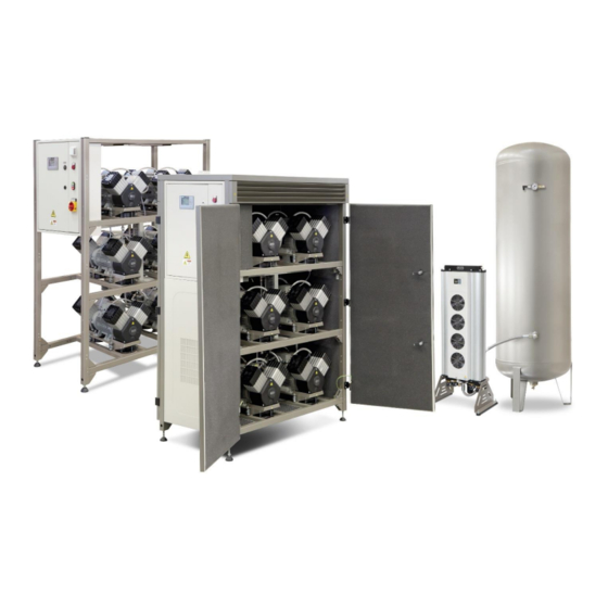
PRODUCT DESCRIPTION PRODUCT DESCRIPTION 7. VARIANTS The compressor is manufactured according to its intended application in the following variants: DK50 4x4VRT/M Composed of modules: compressor module with 4 or 6 aggregates and controls for the DK50 6x4VRT/M assembled unit adsorption dryer with connecting hoses... - Page 10 PRODUCT DESCRIPTION DK 50 6x4VRT/M DK50 4x4VRTS/M NP-DK50-Nx4VRTM-AD-EN-5_04-2022 04/2022...
-
Page 11: Accessories
Accessories that are not included in the 6x4VRT/M performance upgrade kit. standard order must be ordered separately. The DK50 4x4 VRT/M conversion kit converts the existing compressor into a fully functional DK50 4x4VRT/M performance upgrade kit DK50 6x4VRT/M compressor with... - Page 12 PRODUCT DESCRIPTION Article number DK50 4x4VRT/M 447000001-021 DK50 4x4VRTS/M 447000001-020 DK50 6x4VRT/M 447000001-019 DK50 6x4VRTS/M 447000001-018 Where a different level of air Set of compressed air outlet filters filtration required, this The compressor may be equipped with a set requirement must be agreed of filters if specified.
-
Page 13: Product Function
Enclosing the compressor module reduces for S1 class continuous operation. the noise generated by the compressor by up With central intake Article number DK50 4x4VRT/M 447000001-022 DK50 6x4VRT/M DK50 4x4VRT/M 447000001-023 DK50 6x4VRT/M 9. - Page 14 PRODUCT DESCRIPTION Fig. 1 - Compressor with dryer NP-DK50-Nx4VRTM-AD-EN-5_04-2022 04/2022...
- Page 15 PRODUCT DESCRIPTION Fig. 2 – Electrical box / switchboard Descriptions for figures 1-2: Compressor module 13. Connecting hoses Air tank 14. Electrical cables Electrical box / switchboard 15. Drain valve Safety valve 16. Display Pressure sensor 17. Indicator - alarm Pressure gauge 18.
-
Page 16: Technical Data
TECHNICAL DATA TECHNICAL DATA Compressors are designed for operation in dry, ventilated and dust-free indoor rooms under the following climactic conditions: +5°C to +40°C Temperature Relative humidity max. 70% DK50 DK50 DK50 DK50 Working pressure 6 – 8 bar 4x4VRT/M 4x4VRTS/M 6x4VRT/M 6x4VRTS/M... - Page 17 TECHNICAL DATA Specify the compressor version when ordering Consult any other range of pressure with the supplier Weight is indicative and only applies to the product without accessories Applies to ambient temperatures of <30°C PDP – pressure dew point Dependence of compressor output on working pressure 04/2022 NP-DK50-Nx4VRTM-AD-EN-5_04-2022...
- Page 18 TECHNICAL DATA DK50 DK50 DK50 DK50 Working pressure 8 – 10 bar 4x4VRT/M 4x4VRTS/M 6x4VRT/M 6x4VRTS/M Rated voltage V, Hz 3x400, 50 3x400, 50 3x400, 50 3x400, 50 Frequency Output at 8 bar (FAD) at l/min. 1050 1050 PDP-20°C Output at 8 bar (FAD) at l/min.
- Page 19 TECHNICAL DATA Dependence of compressor output on working pressure FAD correction of capacity for altitude Capacity given in the form of FAD („Free Air Delivery“) applies to the following conditions: 20°C Altitude 0 m.n.m. Temperature Atmospheric pressure 101325 Pa Relative humidity To calculate FAD compressor capacity in dependence on altitude, it is necessary to apply correction factor according to the following table: Altitude [m.n.m.]...
-
Page 20: Installation
INSTALLATION INSTALLATION Risk of incorrect installation. Only a qualified technician may install the compressor place it into operation for the first time. Their duty is to train operating personnel on the use maintenance equipment. An entry is made in equipment installation record to certify installation and operator... -
Page 21: Compressor Assembly
Space conditions Temperature +5°C ÷ +40°C Relative humidity 70% Recommended flow of cooling air: DK50 6x4VRT/M - 3000 m DK50 4x4VRT/M – 2250 m Applies for continuous operation and cooling air temperature of20°C Cooling air inlet 11. COMPRESSOR ASSEMBLY are secured to pallets. - Page 22 INSTALLATION Fig. 5: Levelling the compressor Prior to installation, ensure that the compressor is free of all transport packaging stabilizers to avoid any risk of damage to the product. Remove all devices used to secure the aggregates once the compressor is installed and levelled at the site of final installation.
- Page 23 INSTALLATION Fig. 6: Releasing the air pumps DK50 4x4VRT/M – 8 mounts. Remove the transport stabilisers from the air pumps (Fig. 6). DK50 6x4VRT/M – 12 mounts 04/2022 NP-DK50-Nx4VRTM-AD-EN-5_04-2022...
- Page 24 INSTALLATION Air tank assembly Fig. 7:Handling the air tank Position the air tank at the site of At least two persons are needed installation and anchor it to the floor. to handle the equipment. (Fig. 7) Integrated handles are installed on the lower brackets on the product.
-
Page 25: Pneumatic Connection
INSTALLATION Fig. 8: Handling the dryer 12. PNEUMATIC CONNECTION Connect compressor module, dryer module, and the air tank with the provided hoses. (Fig. 9) Fig. 9: Connecting the compressor module, dryer and air tank 04/2022 NP-DK50-Nx4VRTM-AD-EN-5_04-2022... - Page 26 INSTALLATION Fig. 10: Connecting the enclosed compressor module, dryer and air tank hose length 1 [mm] hose length 2 [mm] DK50 4x4VRT/M 1000 DK50 4x4VRTS/M DK50 6x4VRT/M 1300 1000 DK50 6x4VRTS/M 1000 AD dryer compressed air inlet Connect to the compressor outlet (Fig.
- Page 27 INSTALLATION Burn or fire hazard! Caution! Hot surface! When installing the connecting hoses at the inlet to the air dryer, ensure that temperature is not hazardous if it was to come into contact with an operator or other material. AD dryer compressed air outlet ...
-
Page 28: Electrical Connection
INSTALLATION A G3/4” ball valve is installed on the compressed air outlet from the air tank. Fig. 14: Air outlet from the air tank Potential damage pneumatic components. Ensure the air hoses are not kinked. 13. ELECTRICAL CONNECTION Unauthorised interference Connect the compressor module to hazard... - Page 29 INSTALLATION Fig. 15: Connecting the compressor to the dryer Fig. 16: Connecting the control signal 1. Harting connector Proper routing of the electrical cable to the dryer 04/2022 NP-DK50-Nx4VRTM-AD-EN-5_04-2022...
- Page 30 INSTALLATION Fire hazard and risk of electric shock. Ensure the electrical cable does not touch hot parts of the device or connecting hoses. Fig. 17: Connecting the compressor to the pressure sensor Cable bridge NP-DK50-Nx4VRTM-AD-EN-5_04-2022 04/2022...
- Page 31 INSTALLATION Fig. 18: Electrical cord Fig. 19: Connecting the power cord demand and 2 minutes under weak Description of air pump controls demand The air pumps are controlled in trios based on - Pressure drops below real demand. One trio is always set as the (SLAVE) MASTER (e.g.
- Page 32 INSTALLATION Fig. 20: Air pump controls – motors M1-M3 – motors M4-M6 UL – upper limit – bottoms limit → Master = 6.2, SLAVE = 6.0 The regeneration valves open variably based Description of adsorption dryer solenoid on the real load, e.g. if all motors are running, valve control flushing is set to 110 seconds, while if one trio The inlet valves (Inlet A and B) switch every...
- Page 33 INSTALLATION is shipped. Ethernet connection The user then configures the IP The compressor may be connected to an addresses (specific, requested) Ethernet 10/100 M network via the controller based on the manual (see the service as follows: manual) or uses the compressor manufacturer’s technical support for Use the RJ-45 connector on the such purposes.
-
Page 34: Commissioning
INSTALLATION Variables assigned based on addresses and Monitoring memory variables models may be viewed in the MAPPING The “LOGO! Variable” function is the other PARAMETERS table (see Annex option for monitoring compressor parameters chapter). using selected memory variables. Click the Select the variable parameters (per the “LOGO! Variable”... -
Page 35: Pneumatic Diagrams
INSTALLATION 15. PNEUMATIC DIAGRAMS DK50 4x4VRT/M, DK50 4x4VRTS/M 04/2022 NP-DK50-Nx4VRTM-AD-EN-5_04-2022... - Page 36 INSTALLATION DK50 6x4VRT/M, DK50 6x4VRTS/M NP-DK50-Nx4VRTM-AD-EN-5_04-2022 04/2022...
- Page 37 INSTALLATION Description to pneumatic diagrams: 1. Inlet filter 14. Air tank 2. Air pump 15. Drain valve 3. Compressor fan 16. Outlet valve 4. Solenoid valve 17. Dryer solenoid valve 5. Safety valve 18. Central fan 6. Non-return valve 19. Condensate collection vessel 7.
-
Page 38: Operation
OPERATION OPERATION ONLY TRAINED PERSONNEL Potential damage OPERATE pneumatic components. EQUIPMENT! The working pressure settings for the pressure switch set by the manufacturer cannot be Risk of electric shock. changed. Compressor case emergency, operation at a working pressure disconnect compressor below the switching pressure from the mains (pull out the indicates high air usage (see the... -
Page 39: Switching On The Compressor
OPERATION 16. SWITCHING ON THE COMPRESSOR Turn the main switch (19) into the “I” (17) lights up and the display (16) on the switchboard door shows the position compressor following message: switchboard. The white indicator P1 RUN HOURS: operating hours PRESSURE: current pressure TEMP_IN: internal temperature (only for enclosed version) - Page 40 OPERATION Motors are on RUN MODE – all aggregates are switched RUN HOURS: operating hours TIME-TO-GO MN - time to the next maintenance / service work (in hours). Motors are switched off PRESSURE: current working pressure STANDBY MODE – all aggregates are switched off RUN HOURS: operating hours TIME-TO-GO MN - time to the next...
- Page 41 OPERATION F2 – information on operating hours and maintenance intervals. F3 – scrolls through: - Motor malfunctions - Number of motor starts - Maximum temperatures 04/2022 NP-DK50-Nx4VRTM-AD-EN-5_04-2022...
- Page 42 OPERATION F4 - SERVICE TECHNICIAN BUTTON Equipment operation (after completing service or maintenance work Normal operating mode is shown when the - hold for 5 seconds to reset the 2,000 hour equipment is operating and the functional and maintenance interval.) control buttons are used to browse through Note: Pressing F1-3 on the control panel turns the following:...
- Page 43 OPERATION Pressing F4: F4 is only active if the maintenance screen appears once 2000 hours of operation have been passed (see the maintenance alarm). Press and hold F4 for at least 5 seconds to set a new interval. The screen switches back to normal operating mode once the new interval is set.
- Page 44 OPERATION The maintenance/service interval is measured Alarms from the first time the equipment is energised. equipment All alarms are accompanied by a blinking red intelligent monitoring system P2 (Alarm) indicator. that generates an alarm signal based priority (medium Low priority alarm conditions priority alarms have higher ...
- Page 45 OPERATION Compressor module ambient temperature exceeds the limit. WARNING - high ambient temperature alarm. The display flashes orange. This alarm appears ambient temperature exceeds the 40°C limit for at least 30 seconds. The aggregates operate normally. The display otherwise shows the current ambient air temperature.
- Page 46 OPERATION Low pressure alarm during compressor start-up. SIGNALING - Low pressure alarm during compressor start-up. The display is backlit and the P2 alarm indicator flashes. LOW PRESSURE MODE - low pressure signalling in the system with the aggregates switched on. DRYER REGENERATION CYCLING - no purging of the dryer...
-
Page 47: Switching Off The Compressor
OPERATION Alarm signals have priority over All error signals are connected maintenance interval signals. to controller output K3:Q3.2 As such, the light will indicate and to terminals X1:44 and an alarm from any of the X1:45 (in the control panel) as aggregates. -
Page 48: Product Maintenance
PRODUCT MAINTENANCE PRODUCT MAINTENANCE 18. PRODUCT MAINTENANCE The operator shall secure the Danger of injury or equipment completion of repeated testing damage. of the equipment at least once Prior commencing every 24 months (EN 62353) or compressor maintenance, it is at the intervals defined by the necessary to: applicable national regulations. - Page 49 PRODUCT MAINTENANCE Burn hazard. The work below may only be performed by trained personnel as follows: When compressor running or shortly thereafter, Before beginning any of the certain portions of the air pump, following maintenance work, the compressor’s compressed first switch the main switch on air system, parts of the dryer the side of the switchboard to the “0”...
- Page 50 PRODUCT MAINTENANCE 18.1. Maintenance intervals operator qualified technician NP-DK50-Nx4VRTM-AD-EN-5_04-2022 04/2022...
- Page 51 PRODUCT MAINTENANCE qualified technician 04/2022 NP-DK50-Nx4VRTM-AD-EN-5_04-2022...
- Page 52 PRODUCT MAINTENANCE qualified technician NP-DK50-Nx4VRTM-AD-EN-5_04-2022 04/2022...
- Page 53 PRODUCT MAINTENANCE filters or replace with new filters. 18.2. Check of product operation Check the solenoid valves in the valve Check aggregate condition – the module. aggregates should operating normally without excessive vibration or Check the operation of the automatic noise.
- Page 54 PRODUCT MAINTENANCE Condensate from compressors with air dryers is automatically drained into a vessel to collect condensate. Monitor the level in the vessel using the markings (depending on the volume of the vessel), and empty at least once a day. Fig.
- Page 55 PRODUCT MAINTENANCE Turn the screw on the safety valve several rotations to the left until the safety valve releases air. Let the safety valve vent for only a few seconds. Turn the screw to the right until it seats, closing the valve.
- Page 56 PRODUCT MAINTENANCE Fig. 27: Compressor inlet filter cleaning/replacement the disconnection of pressure hoses from air 18.9. Compressor performance check pumps. Turn off the compressor using the One aggregate must be running STOP button. at all times, while the others ...
- Page 57 PRODUCT MAINTENANCE 18.11. Check of solenoid valve operation Check their operation using the “Magnetic indicator” fixture as follows: Attach the fixture to the valve coil and if the motors are active at the valve coil, the indicator must rotate and if they are out of inactive, the indicator must not rotate.
- Page 58 PRODUCT MAINTENANCE manually. First, shut off the compressed air source. Venting compressed air poses Then press and hold ESC+▼, which an injury hazard will open all the solenoid valves (inlet Wearing hearing protection is and regeneration) for 10 seconds and recommended given the noise then vent the pressure from the generated...
- Page 59 PRODUCT MAINTENANCE 18.16. Replacement of the dryer’s In normal operation, filter replacement must internal filters be performed in the upper part of the dryer at the defined interval. Working with pressurised pneumatic components poses a risk of injury. Prior to any work, disconnect the equipment from the mains, shut off the compressor and vent...
- Page 60 PRODUCT MAINTENANCE cassettes with adsorbent media must be 18.17. Replacement of cassettes with performed at the defined interval. adsorbent media In normal operation, the replacement of the Turn off the compressor. Check the pressure in the dryer. If the dryer chambers are under pressure, proceed in accordance with Chapter 17.15.
- Page 61 PRODUCT MAINTENANCE 18.19. Replacement of the dryer’s silencer Working with pressurised pneumatic components poses a risk of injury. Operating equipment without silencers generates high levels of noise. Only replace silencers when equipment is shut down. Unscrew the silencer (1). ...
- Page 62 PRODUCT MAINTENANCE Unscrew the 4 screws (3). Install the new valve seal (4-1). Remove the solenoid valve (4). Install the new solenoid valve using the 4 screws (3) and use a thread Remove the valve seal (4-1) from the locking adhesive on the threads of the body.
- Page 63 PRODUCT MAINTENANCE Fig. 37: Solenoid valve assembly Consultation with 18.22. Pressure relief valve manufacturer is required before The pressure relief valve automatically begins any adjustment is made to the to vent air from the system if the pressure in relief valve! the compressed air circuit exceeds its pre-set The outlet openings on the value.
-
Page 64: Troubleshooting
TROUBLESHOOTING Dryer pressure relief valve Fig. 38: Pressure relief valve TROUBLESHOOTING Risk of electric shock. Troubleshooting may only be performed qualified Before interfering with service technician. equipment, first disconnect it from the mains (remove the power socket). Damage to the safety valve could cause pressure to rise to hazardous levels. - Page 65 TROUBLESHOOTING component (mechanical damage to a moving part) Check controller operation, check to Controller malfunction ensure software is present - replace if damaged or upload the correct program Loss of connection between controller Check connection – replace if damaged and expansion module Check mains voltage Loose terminal in switchboard –...
-
Page 66: Repair Service
TROUBLESHOOTING inlet and dryer connections, check dryer operation, check the dryer’s working pressure, replace defective components. Check compressor’s working Compressor running at high working pressure pressure setting Check coil operation, replace if damaged Air leaking through Dryer inlet solenoid valve not working Inspect the condition of the valve - clean relief valve at dryer the valve or replace if problems persist... -
Page 67: Annex
ANNEX ANNEX 22. MAPPING PARAMETERS 04/2022 NP-DK50-Nx4VRTM-AD-EN-5_04-2022... - Page 68 ANNEX NP-DK50-Nx4VRTM-AD-EN-5_04-2022 04/2022...
-
Page 69: Installation Record
ANNEX 23. INSTALLATION RECORD 1. Product: (model) 2. Serial number: DK50 4X4VRT/M DK50 4x4VRTS/M DK50 6x4VRT/M DK50 6x4VRTS/M 3.1. User’s name: 3.2. Address of installation: 4. Equipment connected to the compressor: 5. Installation / Commissioning: 6. Contents of operator training:... - Page 72 DK50 4x4VRT/M DK50 6x4VRT/M EKOM spol. s r.o., Priemyselná 5031/18, 921 01 PIEŠŤANY, Slovak Republic tel.: +421 33 7967255, fax: +421 33 7967223 e-mail: ekom@ekom.sk, www.ekom.sk NP-DK50-Nx4VRTM-AD-EN-5_04-2022 112000399-0001...
Need help?
Do you have a question about the DK50 4x4VRT/M and is the answer not in the manual?
Questions and answers