Table of Contents
Advertisement
Quick Links
Advertisement
Table of Contents

Subscribe to Our Youtube Channel
Related Manuals for EKOM DK50 3x4VR/M


Summary of Contents for EKOM DK50 3x4VR/M
- Page 1 DK50 3x4VR/M User manual...
- Page 3 COMPRESSOR DK50 3x4VR/M EKOM spol. s r. o. Priemyselná 5031/18 SK-921 01 Piešťany Slovak Republic tel.: +421 33 7967255 fax: +421 33 7967223 www.ekom.sk email: ekom@ekom.sk DATE OF LAST REVISION 06/2022 NP-DK50 3x4VR_M-AD-A- EN-3_06-2022 112000554-0001...
-
Page 4: Table Of Contents
CONTENTS CONTENTS GENERAL INFORMATION ......................5 CONFORMITY WITH THE REQUIREMENTS OF THE EUROPEAN UNION ....5 SYMBOLS ........................5 DEVICE USE........................6 GENERAL SAFETY INSTRUCTIONS ................7 STORAGE AND TRANSPORT CINDITIONS ..............8 PRODUCT DESCRIPTION ......................9 VARIANTS ........................9 ACCESSORIES ...................... -
Page 5: General Information
GENERAL INFORMATION GENERAL INFORMATION protection of its configuration, processes and names. Carefully read this user manual before using The Slovak version represents the original the product and carefully store it for future version of the user manual. The translation of reference. -
Page 6: Device Use
GENERAL INFORMATION Fuse Compressed air inlet - dryer Compressed air outlet - dryer Control wire input Package handling label – fragile Package handling label – this side up Package handling label – keep dry Package handling label – temperature limits Package handling label –... -
Page 7: General Safety Instructions
GENERAL INFORMATION 4. GENERAL SAFETY INSTRUCTIONS The product is designed and manufactured so 4.3. Protection from dangerous that any risks connected with its use are voltage and pressure minimized and the product is safe for the user The equipment may only be connected to a and surrounding when used according to the intended use and the instructions stated below properly installed socket connected to... -
Page 8: Storage And Transport Cinditions
GENERAL INFORMATION 5. STORAGE AND TRANSPORT CINDITIONS compressor shipped from Keep original factory manufacturer in transport packaging. This packaging in case the device protects the product from damage during needs to be returned Use the transport. original factory packaging during transport as it provides Potential damage optimum protection for the... -
Page 9: Product Description
PRODUCT DESCRIPTION PRODUCT DESCRIPTION 6. VARIANTS The compressor is manufactured according to its intended application in the following variants: DK50 3x4VR/M Comprised of module: Compressor module Adsorption dryer module AD750E DK50 3x4VR/M The compressed air supplied by the compressor is unsuitable... -
Page 10: Product Function
PRODUCT DESCRIPTION Level of filtration Bypass Type Article number (µm) function * FS 40F 604014119-000 FS 40M 1+0.1 604014119-004 DK50 3x4VR FS 40S 1+0.01 604014119-024 FS 40AH 1+AC+HC(0.01) 604014119-005 *) These FS do not contain a filter bypass, pressure regulator of the compressed air which will ensure a continuous flow of air outlet if specified. - Page 11 PRODUCT DESCRIPTION Descriptions for figures 1 - 3 23 Circuit breaker Air pump 24 Contactor Air tank 25 Motor circuit breaker Non-return valve 26 Power supply 27 Logo DM8 Safety valve 28 Logo text display Pressure gauge 29 Pressure relief valve Drain valve 30 Common pump...
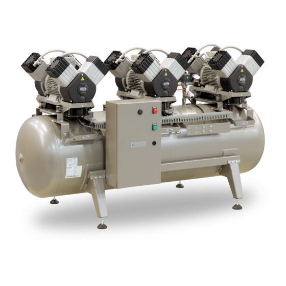
- Page 12 PRODUCT DESCRIPTION Fig. 1: DK50 3x4VR/M – Compressor with adsorption dryer NP-DK50 3x4VR_M-AD-A-EN-3_06-2022 06/2022...
- Page 13 PRODUCT DESCRIPTION Fig. 2: Adsorption dryer 06/2022 NP-DK50 3x4VR_M-AD-A-EN-3_06-2022...
- Page 14 PRODUCT DESCRIPTION Fig. 3: Switchboard NP-DK50 3x4VR_M-AD-A-EN-3_06-2022 06/2022...
-
Page 15: Technical Data
Compressors are designed for operation in dry, ventilated and dust-free indoor rooms under the following climactic conditions: +5°C to +40°C Temperature Relative humidity max. 70% Working pressure 6 – 8 bar DK50 3x4VR/M Nominal voltage, Frequency V, Hz 3x400, 50 Capacity at 6 bar (FAD) -20°C l/min 6.0 – 8.0... - Page 16 TECHNICAL DATA Working pressure 6 – 8 bar DK50 3x4VR/M Nominal voltage, Frequency V, Hz 3x400, 50 Capacity at 6 bar (FAD) -40°C l/min 6.0 – 8.0 Working pressure Rated current 15.9 Main circuit protection device rating Main electrical feeder 5C x 1.5...
- Page 17 TECHNICAL DATA Dependence of compressor output on working pressure FAD correction of capacity for altitude Capacity given in the form of FAD („Free Air Delivery“) applies to the following conditions: 20°C Altitude 0 m.n.m. Temperature Atmospheric pressure 101325 Pa Relative humidity To calculate FAD compressor capacity in dependence on altitude, it is necessary to apply correction factor according to the following table: Altitude [m.n.m.]...
-
Page 18: Installation
INSTALLATION INSTALLATION Risk of incorrect installation. Only a qualified technician may install the compressor place it into operation for the first time. Their duty is to train operating personnel on the use maintenance equipment. An entry is made in equipment installation record to certify installation and operator... -
Page 19: Compressor Assembly
INSTALLATION Fig. 4: Equipment installation Air outlet Space conditions Temperature +5°C ÷ +40°C - Relative humidity 70% Recommended flow of cooling air: DK50 3x4VRT/M - 1850 m3/h. Applies for continuous operation and cooling air temperature of 20°C Cooling air inlet 10. - Page 20 INSTALLATION Fig. 5: Handling the compressor Remove the transport stabilisers from the Prior to installation, ensure that air pumps – 6 mounts (Fig. 6). the compressor is free of all transport packaging stabilizers to avoid any risk of damage to the product. Remove all devices used to secure the aggregates once the compressor is installed and...
- Page 21 INSTALLATION Fig. 6: Releasing the air pumps Assembly of the AD dryer Manipulation Remove the dryer from the packaging. At least two persons are needed to handle the equipment. Install the dryer in its operating position (Fig. 7). Integrated handles are installed on the lower brackets on the product.
-
Page 22: Pneumatic Connection
INSTALLATION Fig. 7: Handling the dryer 11. PNEUMATIC CONNECTION compressor outlet (1) to the dryer inlet (2) 11.1. Connecting the dryer to the and is routed together with hose B using compressor double clips (3). Connect the compressor assembly using the ... - Page 23 INSTALLATION Fig. 8: Connecting the dryer to the compressor 06/2022 NP-DK50 3x4VR_M-AD-A-EN-3_06-2022...
- Page 24 INSTALLATION Risk of fire and electric shock. Ensure the power cord does not touch parts equipment connecting hoses. AD dryer compressed air inlet Connect the compressed air outlet from the air tank to the dryer inlet (1). Use the shorter of the provided hoses. (2800 mm).
-
Page 25: Electrical Connection
INSTALLATION Compressed air outlet from the compressor A G1/2” female threaded end ball valve is installed on the compressed air outlet from the air tank (M). Fig. 11: Air outlet from the air tank piping or to the provided collection vessel. Condensate outlet from dryer A noise silencer is recommended when ... - Page 26 INSTALLATION Fig. 13: Connecting the W22 connection cable Fig. 14: Connecting the control signal 1. Connector Harting Risk of fire and electric shock. Electrical cable must not be in contact with hot compressor components. NP-DK50 3x4VR_M-AD-A-EN-3_06-2022 06/2022...
- Page 27 INSTALLATION Fig. 15: Power terminals L1, L2, L3 Risk of electric shock. Ethernet network. (Fig. 16). Configuration of the IP address to connect It is necessary to follow all local electro technical regulations. to the local network: mains voltage The default IP address of the BM frequency must comply with the module...
- Page 28 INSTALLATION Fig. 16: Ethernet network connection Opera, Safari, Google Chrome , etc / Web Server The process for logging into the Web Server The controller of dryer has an integrated Web function once the compressor is connected to Server function that facilitates compressor an Ethernet network is as follows: monitoring via a PC, smartphone or tablet using a conventional web browser (Firefox,...
-
Page 29: Commissioning
INSTALLATION Click on the “LOGO! BM” function in the browser to display the current virtual status of the BM text display screen. Navigate through the screen using the cursor keys the same as on the real display. 13. COMMISSIONING ... -
Page 30: Pneumatic Diagram
INSTALLATION 14. PNEUMATIC DIAGRAM DK50 3x4VR/M NP-DK50 3x4VR_M-AD-A-EN-3_06-2022 06/2022... - Page 31 INSTALLATION Description to pneumatic diagram: Inlet filter 13 Cooler fan Compressor 14 Air tank 15 Condensate drain valve OR logic valve 16 Outlet valve Safety valve 17 Dryer solenoid valve Non-return valve 18 Chamber inlet filter Pressure valve 19 Adsorbent Condensate separator 20 Chamber outlet filter Condensate collection vessel...
-
Page 32: Operation
OPERATION OPERATION ONLY TRAINED PERSONNEL Potential damage OPERATE pneumatic components. EQUIPMENT! The working pressure settings for the pressure switch set by the manufacturer cannot be Risk of electric shock. changed. Compressor case emergency, operation at a working pressure disconnect compressor below the switching pressure from the mains (pull out the indicates high air usage (see the... -
Page 33: Switching On The Compressor
OPERATION 15. SWITCHING ON THE COMPRESSOR Turn the main switch into the “I” position on appears on the display on the door of the switchboard, the display shows: RUN the compressor switchboard. A message MODE or STAND-BY MODE MOTORS : OFF or ON ... -
Page 34: Ad Dryer Operating Modes
OPERATION TOT.HOURS total time the compressor has been energised HOURS RUN: operating hours (motors TIME-TO-GO MN - time to the next maintenance / service work SERVICE COMP: number of 2,000 h maintenance checks performed on the compressor. - Page 35 OPERATION Display unit Home screen The home screen appears for 5 seconds when the main switch S1 on the dryer is switched to the “I” position „Adsorption dryer ADxx00Sis ON“ The display is backlit in white. The home screen is followed by the RUN MODE and STAND BY MODE screens based on the compressor control signal.
- Page 36 OPERATION Indication of an upcoming service interval 100 hours prior to the next service interval, the back lighting changes from white to orange and the display shows the message “SERVICE DUE IN XY HOURS”, where XY indicates the remaining number of hours until service is due.
- Page 37 OPERATION Pressing F2: TOT.HOURS: total time the compressor has been energised HOURS RUN: operating hours (motors on) TIME-TO-GO MN - time to the next maintenance / service work SERVICE COMPR: number of 2,000 h maintenance checks performed on the compressor SERVICE DRYER: number...
- Page 38 OPERATION This alarm activates once the 2,000 hour Press F4 and hold for at least 5 seconds to maintenance / service interval expires. The confirm the completion of maintenance / display shows the following details: service. SERVICE ACCORDING The display then changes to the normal INSTRUCTIONS FOR USE operating mode screen.
-
Page 39: Switching Off The Compressor
OPERATION Fault - motor winding temperature fault The message on the display (ERROR) and blinking ALARM indicator indicate which of the aggregate motors has malfunctioned (open thermal overload switch (B11 - B13) inside the motor winding (M1 - M3). The malfunction in the air pump may be mechanical or electrical. -
Page 40: Product Maintenance
PRODUCT MAINTENANCE PRODUCT MAINTENANCE 18. PRODUCT MAINTENANCE The operator should carry out Danger of injury or equipment device checks regularly in the damage. intervals defined by applicable Prior commencing regulations. Test results must compressor maintenance, it is be recorded. necessary to: The equipment has been designed and check if it is possible to manufactured to keep maintenance to a... - Page 41 PRODUCT MAINTENANCE Burn hazard. removed grounding conductor during service must When compressor be connected back to running or shortly thereafter, original position after certain portions of the air pump completing the service. and parts of the dryer may be hot - do not touch these components.
- Page 42 PRODUCT MAINTENANCE 18.1. Maintenance intervals operator qualified technician NP-DK50 3x4VR_M-AD-A-EN-3_06-2022 06/2022...
- Page 43 PRODUCT MAINTENANCE Qualified technician 06/2022 NP-DK50 3x4VR_M-AD-A-EN-3_06-2022...
- Page 44 PRODUCT MAINTENANCE clearance in the crankshaft. 18.2. Check of product operation Check the functionality of the automatic Check air pump condition – the air pumps condensate drain. should be operating normally without Replace any defective parts as needed. excessive vibration or noise.
- Page 45 PRODUCT MAINTENANCE vessel. Tighten any loose terminals. service interval Inspect the connector and pressure sensor Configuration of a new service interval B1 (on the air tank). Press ESC + ► together and hold for 10 seconds to reset the service interval. Once Checking the operating condition of the complete, the display returns back to the AD dryer...
- Page 46 PRODUCT MAINTENANCE ESC+▲– „OPERATING TIME“ screen information on operating hours: TOTAL, RUN, STAND BY, time remaining to the next service interval and value of the defined service interval TOTAL HRS – total time the dryer has been energised RUN HRS – total dryer cycling time STAND.HRS –...
- Page 47 PRODUCT MAINTENANCE 18.6. Inlet filter replacement Inlet filter replacement: Pull out the rubber plug by hand (2). Remove the dirty intake filter (1). Insert a new filter and replace the rubber plug. Pre-filter replacement: Pull out the pre-filter by hand (3). ...
- Page 48 PRODUCT MAINTENANCE pump must Check for proper operation of the non-return operating, shut valve (31) on the air tank by disconnecting the remaining air pumps at the pressure hose from the valve current protection device (25) in Inspect the non-return valve the switchboard.
- Page 49 PRODUCT MAINTENANCE First, shut off the compressed air source. equipment by the check valve Then press and hold ESC+▼, which will Manual venting of pressure open all the solenoid valves (inlet and Turn off the compressor. regeneration) for 10 seconds and then vent the pressure from the equipment and ...
- Page 50 PRODUCT MAINTENANCE Turn off the compressor. Check the pressure in the dryer. If the dryer chambers are under pressure, proceed in accordance with Chapter 18.13. Unscrew the 8 screws (1). Disassemble the outlet panel (2) on which the filters (3) are mounted.
- Page 51 PRODUCT MAINTENANCE 18.16. Replacement of the logic valve ball Turn off the compressor. Check the pressure in the dryer. If the dryer chambers are under pressure, proceed in accordance with Chapter 18.13. Unscrew the 4 screws (1) and remove the cover (2).
- Page 52 PRODUCT MAINTENANCE Check the pressure in the dryer. 18.18. Inspecting the cooled and fan If the dryer chambers are under pressure, The equipment, in particular the compressor proceed in accordance with Chapter 18.13. fan, cooler fan, and the cooler, must be kept ...
- Page 53 PRODUCT MAINTENANCE Fig. 27: Solenoid valve replacement body (4-4) and secure with the nut (4-6). Solenoid valve assembly Insert the valve membrane spring (4-3) into Replacement solenoid valves are delivered as the membrane (4-2) and the insert into the disassembled replacement parts.
-
Page 54: Long-Term Shutdown
PRODUCT MAINTENANCE value. The pressure relief valve closes as the Consultation with manufacturer is required before pressure drops. any adjustment is made to the pressure relief valve! compressed air circuit can only increase because The outlet openings on the increase in flow resistance in relief valve may not be blocked the compressed air lines or as a and the egress of compressed... -
Page 55: Disposal Of Device
PRODUCT MAINTENANCE mains. 20. DISPOSAL OF DEVICE Disconnect the equipment from the mains. applicable regulations. Entrust a specialised company to sort and Release the air pressure in the pressure dispose of waste. tank by opening the drain valve (7) (Fig. 1), release the air pressure from the dryer ... -
Page 56: Troubleshooting
TROUBLESHOOTING TROUBLESHOOTING Troubleshooting may only be performed qualified Risk of electric shock. service technician. Before interfering with equipment, first disconnect it Damage to the safety valve from the mains (remove the could cause pressure to rise to power socket). hazardous levels. Never adjust a safety valve. - Page 57 TROUBLESHOOTING regeneration is complete damaged Leak at pressure sensor and safety Test their function and clean, or valve replace if damaged Decrease air consumption High air consumption of supplied Use compressor with higher equipment capacity Low pressure in Check pneumatic system – seal the air tank Leakage in pneumatic system loose connections...
-
Page 58: Repair Service
TROUBLESHOOTING dryer’s working pressure, and replace defective components. High working pressure from air Check the pressure setting on the source compressed air source Check the coil operation, replace if damaged Air leaking through Dryer inlet solenoid valve not Inspect the condition of the valve – relief valve at dryer working clean the valve or replace if... -
Page 59: Annex
ANNEX ANNEX 22. INSTALLATION RECORD 1. Product: (model) 2. Serial number: DK50 3x4VR/M 3.1. User’s name: 3.2. Address of installation: 4. Equipment connected to the compressor: 5. Installation / Commissioning: 6. Contents of operator training: Product completeness check ** Description of the product and functions**... - Page 64 DK50 3x4VR/M EKOM spol. s r.o., Priemyselná 5031/18, 921 01 PIEŠŤANY, Slovak Republic tel.: +421 33 7967255, fax: +421 33 7967223 e-mail: ekom@ekom.sk, www.ekom.sk NP-DK50 3x4VR_M-AD-A-EN-3_06-2022 112000554-0001...
Need help?
Do you have a question about the DK50 3x4VR/M and is the answer not in the manual?
Questions and answers