Table of Contents
Advertisement
Quick Links
Advertisement
Table of Contents

Related Manuals for GigaDevice Semiconductor GD32E230C-START


Summary of Contents for GigaDevice Semiconductor GD32E230C-START
- Page 1 GigaDevice Semiconductor Inc. GD32E230C-START User Guide V1.0...
-
Page 2: Table Of Contents
User Guide GD32E230C-START Table of Contents Table of Contents ..........................1 List of Tables ............................. 2 Summary ............................ 3 Function Pin Assign ........................3 Getting started ........................... 3 Hardware layout overview ......................4 Power ........................... 4 Boot ............................4 LED............................4 KEY ............................ -
Page 3: List Of Tables
User Guide GD32E230C-START List of Tables Table 1. Function pin assign .......................... 3 Table 2. Revision history ..........................10 2/ 11... -
Page 4: Summary
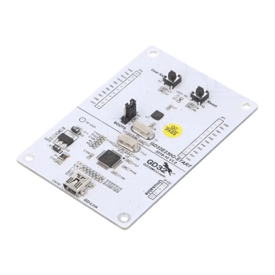
User Guide GD32E230C-START Summary GD32E230C-START uses GD32E230C8T6 as the main controller. It uses Mini USB interface to supply 5V power. Reset, Boot, Wakeup key, LED, GD-Link and Ardunio are also included. For more details please refer to GD32E230C-START-V1.0 schematic. Function Pin Assign Table 1. -
Page 5: Hardware Layout Overview
User Guide GD32E230C-START Hardware layout overview Power Boot BOOT0 10KΩ +3V3 BOOT0 LED1 470Ω LED0603 LED2 470Ω LED0603 LED3 PA11 470Ω LED0603 LED4 PA12 470Ω LED0603 4/ 11... -
Page 6: Key
User Guide GD32E230C-START GD-Link MCU SWD PA0-WKUP PB2/BOOT1 +3V3 JP100 PB3/JTDO L_TMS/IO PB4/JNTRST L_SWDIO L_TCK/CLK L_SWDCK L_TDO/SWO L_TDI 4× 1P2.54 L_USB_Ctr L_TReset L_LED1 LED0603 PA10 PB10 L_USB_DM PA11 PB11 L_USB_DP L_LED1 R109 470Ω PA12 PB12 L_SWDIO L_LED2 R110 470Ω PA13/JTMS/SWDIO... -
Page 7: Mcu
User Guide GD32E230C-START GDLink SWDAT L_TMS/IO SWCLK L_TCK/CLK NRST L_TReset 32.768KHz PC15 50V/10pF PC14 50V/10pF PA10 PB10 PA10 PB10 PA11 PB11 PA11 PB11 PA12 PB12 HC-49S-8MHz PA12 PB12 SWDAT PA13 PB13 OSC_IN PA13/SWDAT PB13 SWCLK PA14 PB14 PA14/SWCLK PB14 50V/20pF... -
Page 8: Routine Use Guide
Learn to use SysTick to generate 1ms delay GD32E230C-START board has two keys and four LEDs. The two keys are Reset key and Wakeup key. The LED1, LED2, LED3 and LED4 are controlled by GPIO. This demo will show how to use the Wakeup key to control the LED1. When press down the Wakeup Key, it will check the input value of the IO port. -
Page 9: Exti_Keyboard_Interrupt_Mode
Learn to use EXTI to generate external interrupt GD32E230C-START board has two keys and four LEDs. The two keys are Reset key and Wakeup key. The LED1, LED2, LED3 and LED4 are controlled by GPIO. This demo will show how to use the EXTI interrupt line to control the LED1.When press down the Wakeup Key, it will produce an interrupt. - Page 10 User Guide GD32E230C-START 5.4.2 DEMO Running Result Download the program < 04_TIMER_KeyBoard_EXTI > to the EVAL board, all the LEDs are flashed once for test, press down the Wakeup Key, LED1 will be turned on. Press down the Wakeup Key again, LED1 will be turned off. Connect PA6(TIMER2_CH0) and PB11 with DuPont line.
-
Page 11: Revision History
User Guide GD32E230C-START Revision history Table 2. Revision history Revision No. Description Date Initial Release Oct.25, 2018 10/ 11... - Page 12 Important Notice This document is the property of GigaDevice Semiconductor Inc. and its subsidiaries (the "Company"). This document, including any product of the Company described in this document (the “Product”), is owned by the Company under the intellectual property laws and treaties of the People’s Republic of China and other jurisdictions worldwide.
Need help?
Do you have a question about the GD32E230C-START and is the answer not in the manual?
Questions and answers